Format: PDF (Printable Document)
File Language: English
Brand: BT
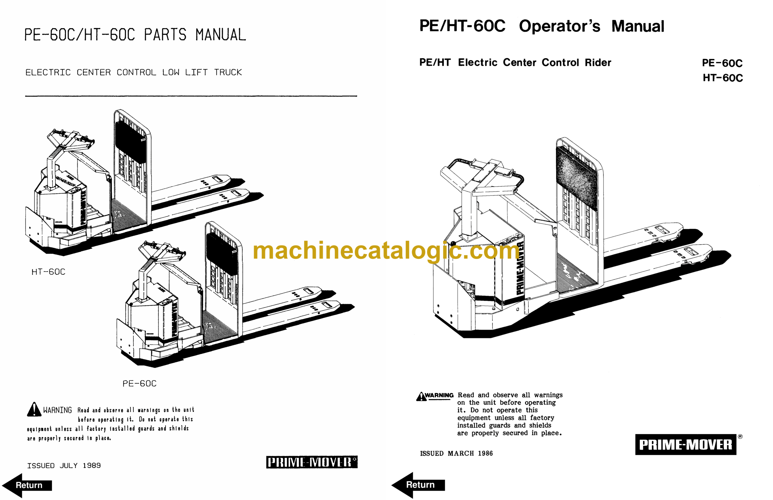
Model: PE60C, HT60C Electric Stacker
Type of Document: Operator and Parts Manual
$ 70
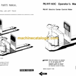
BT PE60C, HT60C Electric Stacker Operator and Parts Manual
Front Cover
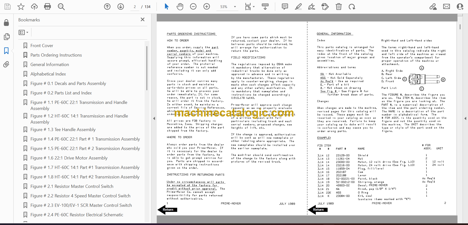
Parts Ordering Instructions
General Information
Alphabetical Index
Figure # 0.1 Decals and Parts Assembly
Figure # 0.2 Parts List and Index
Figure # 1.1 PE-60C 22:1 Transmission and Handle Assembly
Figure # 1.2 HT-60C 14:1 Transmission and Handle Assembly
Figure # 1.3 Tee Handle Assembly
Figure # 1.4 PE-60C 22:1 Part # 1 Transmission Assembly
Figure # 1.5 PE-60C 22:1 Part # 2 Transmission Assembly
Figure # 1.6 22:1 Drive Motor Assembly
Figure # 1.7 HT-60C 14:1 Part #1 Transmission Assembly
Figure # 1.8 HT-60C 14:1 Part #2 Transmission Assembly
Figure # 2.1 Resistor Master Control Switch
Figure # 2.2 Resistor 4 Speed Master Control Switch
Figure # 2.3 EV-100/EV-1 SCR Master Control Switch
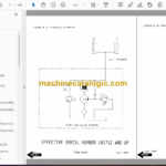
Figure # 2.4 PE-60C Resistor Electrical Schematic
Figure # 2.5 Resistor Electrical Schematic Symbols
Figure # 2.6 PE-60C Third Speed Control Wiring
Figure # 2.7 12 Volt PE-60C Third Speed Power Component Wiring
Figure # 2.8 24 Volt PE-60C Third Speed Power Component Wiring
Figure # 2.9 Control Panel Assembly
Figure # 2.10 Contactor Assembly
Figure # 2.11 Forward & Rearward Contactor Assembly
Figure # 2.12 Third Speed Contactor Panel Assembly
Figure # 2.13 PE-60C Third Speed Contactor Assembly
Figure # 2.14 HT-60C Resistor Electrical Schematic
Figure # 2.15 Resistor Electrical Schematic Symbols
Figure # 2.16 HT-60C Third Speed Control Wiring
Figure # 2.17 HT-60C Third Speed Power Component Wiring
Figure # 2.18 HT-60C Resistor Control Panel Assembly
Figure # 2.19 HT-60C Third Speed Contactor Panel Assembly
Figure # 2.20 HT-60C Fourth Speed Control Wiring
Figure # 2.21 HT-60C Fourth Speed Power Component Wiring
Figure # 2.22 HT-60C Fourth Speed Contactor Panel Assembly
Figure # 2.23 EV-100 SCR Trucks Electrical Schematic
Figure # 2.24 EV-100 SCR Truck Electrical Schematic Symbols
Figure # 2.25 EV-100 SCR Control Wiring
Figure # 2.26 HT-60C EV-100 SCR Two Speed Power Component Wiring
Figure # 2.27 EV-100 SCR Contactor Panel Assembly
Figure # 2.28 EV-100 SCR Forward & Rearward Contactor Assembly
Figure # 2.29 EV-100 1A Contactor Assembly
Figure # 2.30 HT-60C EV-100 SCR Two Speed Pump Contactor Panel Assembly
Figure # 2.31 EV-100 SCR Three Speed Power Component Wiring
Figure # 2.32 EV-100 SCR Three Speed Contactor Panel Assembly
Figure # 2.33 EV-100 SCR Two & Three Speed Control Panel
Figure # 2.34 Power Connector Assembly
Figure # 2.35 Hydraulic Pump Motor Assembly
Figure # 2.36 PE-60C Drive Motor Assembly
Figure # 2.37 HT-60C 14:1 Drive Motor Assembly
Figure # 2.38 Wiring Assembly for Cold Storage
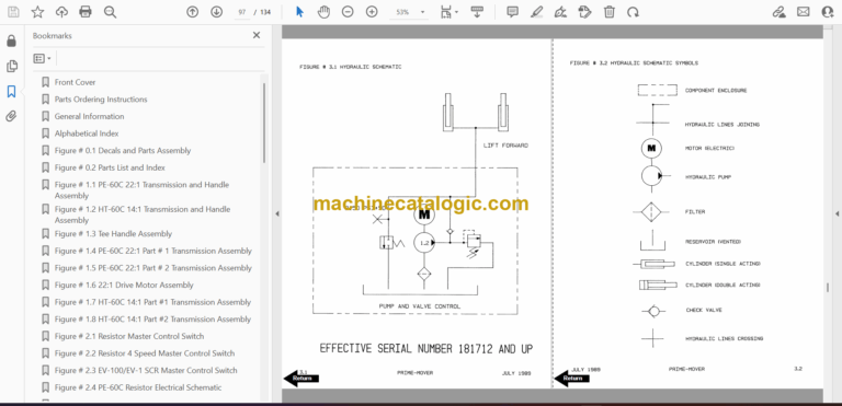
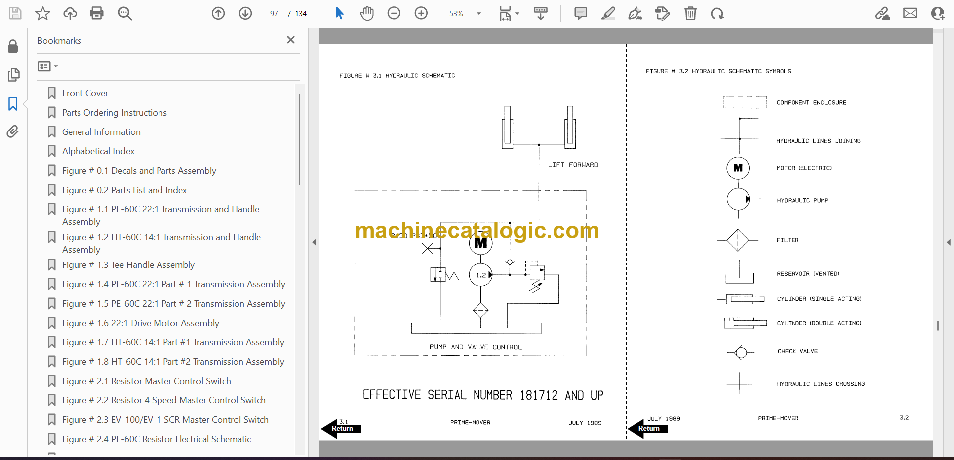
Figure # 3.1 Hydraulic Schematic
Figure # 3.2 Hydraulic Schematic Symbols
Figure # 3.3 Hydraulic System
Figure # 3.4 Pump and Motor Assembly
Figure # 3.5 Lift Cylinder Assembly
Figure # 4.1 Shielding Assembly
Figure # 4.2 Carrier Frame Assembly
Figure # 4.3 Caster Assembly
Figure # 4.4 Lift Frame Assembly
Figure # 4.5 Pallet Entry Rollers
Figure # 4.6 Rider Compartment and Padding Assembly
Figure # 6.1 Special Tools and Lubrications
Numerical Index
Back Cover
Front Cover
Warranty
Introduction to Owner
Contents
Preliminary Service
Operation
Operating Rules and Instructions
Field Modification
Safety
Data Plate
Controls
Before Operation
Operation
Parking
Periodic Maintenance Chart
Lubrication
Flush Grease Fitting
Lubrication Chart
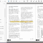
Maintenance Instructions
Battery
Theory of Electrical Operations
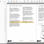
Master Control Switch
Brake Theory of Operation
Motor Commutator
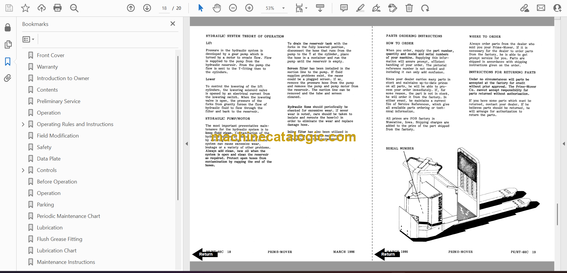
Hydraulic System Theory of Operation
Parts Ordering Instructions
Back Cover

