Format: PDF (Printable Document)
File Language: English
File Pages: 618
File Size: 16.56 MB (Speed Download Link)
Brand: BT
Model: RR M12, RR M14, RR M16, RRE120M, RRE140M, RRE160M Reach Truck
Part No: 930971-, 6011354-
Type of Document: Master Service Manual
$ 40
1- Table of contents
2- General introduction
2.1 How to use this manual
2.2 Warning levels and symbols
2.3 Pictograms
2-
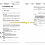
3- General safety rules
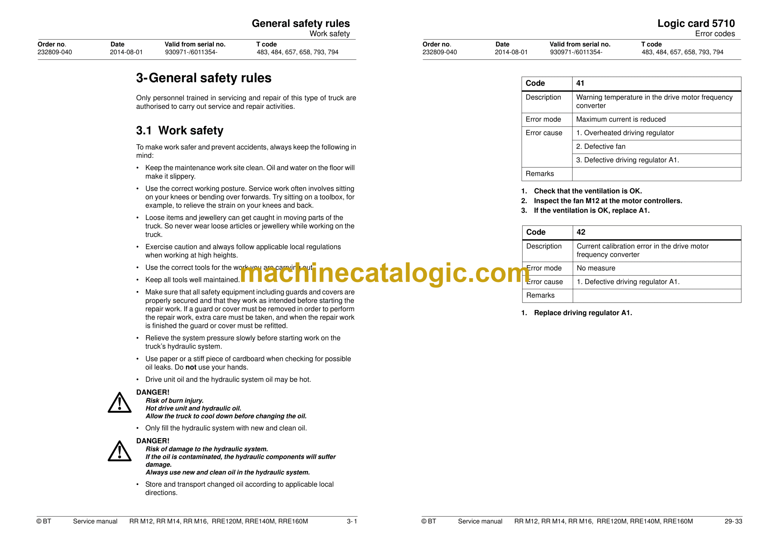
3.1 Work safety
3.2 Electrical system
3.3 Safe lifting
3.4 Truck modifications
4- Installation
4.1 Transporting the truck
4.2 Transporting the mast
4.3 Safe lifting
5- Technical data 1
5.1 General tightening torques
6- Technical data 2
6.1 General tightening torques
7- Introduction, maintenance
7.1 Safety precautions for maintenance work
7.2 Cleaning and washing
7.3 Safe lifting
8- Preventive maintenance
8.1 Maintenance schedule
9- Oil and grease specifications
10- Tools
10.1 Super Seal contact
11- Operator protection – 0840
11.1 General
11.2 Studs
12- Electric pump motor – 1710
12.1 General
12.2 Disassembled pump motor
12.3 Disassembly and assembly of the pump motor
12.4 Replacing the ball bearing
13- Electric steering motor – 1730
13.1 General
13.2 Replacing the steering motor
13.3 Disassembly and assembly of the carbon brushes
14- Electric drive motor – 1760.1
14.1 General
14.2 Disassembled drive motor
14.3 Disassembly and assembly of the drive motor
14.4 Replacing the ball bearing
14.5 Installation instructions for the external temperature sensor
15- Electric drive motor – 1760.2
RRE120M, RRE140M, RRE160M
15.1 General
15.2 Remove and install drive motor
15.3 Replacing the rotational speed sensor
16- Drive unit/gear – 2550.1
16.1 General
16.2 Components/data for the drive assembly/transmission
16.3 Replacing the drive motor/drive gear
16.4 Oil level check/change
16.5 Repairs
17- Drive unit/gear – 2550.2
RRE120M, RRE140M, RRE160M
17.1 General
17.2 Components/data for the drive assembly/gear
17.3 Replacing the drive motor/drive gear
17.4 Replacing the steering bearing
17.5 Restore the truck
17.6 Oil level check/change
17.7 Replacing the wheel bolt
17.8 Replacing the gear wheel
17.9 Installing the bearing on the wheel axle
18- Service brake system – 3100.1
18.1 General
18.2 Function description
18.3 Electro-mechanical disc brake, drive motor
18.4 Dismantling
18.5 Inspection
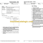
18.6 Fitting
18.7 Maintenance
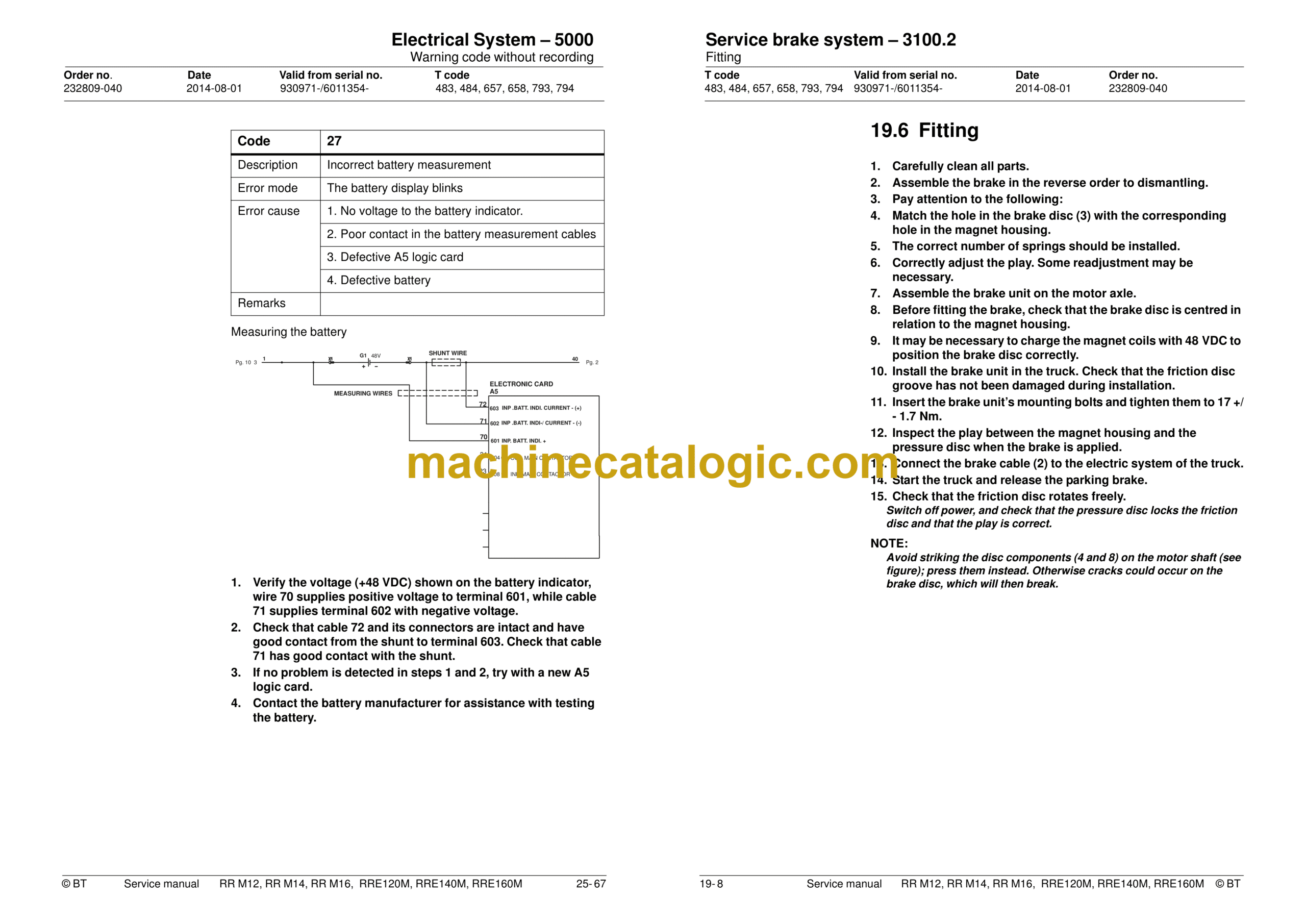
19- Service brake system – 3100.2
RRE120M, RRE140M, RRE160M
19.1 General
19.2 Function description
19.3 Electro-mechanical disc brake, drive motor
19.4 Dismantling
19.5 Inspection
19.6 Fitting
19.7 Maintenance
20- Drive wheel – 3530
20.1 General
20.2 Dismantling the drive wheel
20.3 Assembling the drive wheel
21- Fork/support arm wheel – 3550
21.1 General
21.2 Dismantling the wheel
21.3 Fitting the support arm wheel
21.4 Dismantling the wheel bearings
21.5 Assembling the wheel bearings
22- Mechanical steering system – 4100
22.1 General
22.2 Replacing the steering generator
23- Steering angle sensor – 4350
23.1 General
23.2 Procedure
24- Electrical system – 5000.1
24.1 General
24.2 Symbol list and electric wiring diagram
24.3 Description of operation
25- Electrical System – 5000
RRE120M, RRE140M, RRE160M
25.1 Electric panel
25.2 Symbol list and electric wiring diagram
25.3 General wiring diagram
25.4 Wiring diagram
25.5 Function description
25.6 Display and programming
25.7 Parameters
25.8 Operating time
25.9 Warning codes
25.10 Error codes
25.11 Warning code without recording
25.12 Keypad
26- Battery – 5110
26.1 Battery dimensions
26.2 Setting battery parameters with Hawker Evolution gel batteries
27- Transistor panel – 5460
27.1 Frequency converter.
28- Power electronic panel – 5660
28.1 General description
28.2 Diagnostics and troubleshooting
28.3 Maintenance
29- Logic card 5710
29.1 General description
29.2 Connection terminals and voltages on A5
29.3 Adjusting the lowering speed
29.4 Display
29.5 Programming
29.6 Warning codes
29.7 Error codes
29.8 Warning codes with registration
29.9 Error codes
29.10 Operating Time
29.11 Setting all
30- Hydraulics – 6000
30.1 General
30.2 Symbols
30.3 List of symbols
30.4 Adjusting fork lowering
30.5 Adjusting the maximum lifting capacity
31- Hydraulic pump – 6140
31.1 General
31.2 Replacing the hydraulic pump
32- Hydraulic couplings – 6230
32.1 General
32.2 Tightening torques for hydraulic connections
33- Mast-mounted hose reel – 6370
33.1 General
33.2 Fitting
33.3 Checks after fitting
34- Hydraulic cylinder – 6600
34.1 General
34.2 Duplex mast
34.3 Triplex mast:
34.4 Cylinder seals
34.5 Replacing wear parts in the cylinder
35- Main lift cylinder – 6610
35.1 General
35.2 Tools
35.3 Dismantling the lift cylinders from the mast
35.4 Dismantling the cylinder
35.5 Assembling the cylinder
36- Free lift cylinder – 6620
36.1 General
36.2 Tools
36.3 Dismantling
36.4 Dismantle the rod seal and support ring.
36.5 Dismantling the piston
36.6 Dismantling and assembling the hose rupture valve
36.7 Assembling the cylinder
36.8 Fitting
37- Reach cylinder – 6650
37.1 General
37.2 Assembling and dismantling the reach cylinder
37.3 Fitting
38- Tilt cylinder – 6660.1
38.1 General
38.2 Assembling and dismantling the tilt cylinder
38.3 Fitting
39- Tilt cylinder – 6660.2
39.1 General
39.2 Mast with valve on the fork carriage
39.3 Mast without valve on the fork carriage.
40- Main mast/mast – 7100.1
40.1 General
40.2 Tool list
40.3 Transporting the truck
40.4 Assembling the mast
40.5 Disassembling the mast
40.6 Assembling Duplex mast
40.7 Assembling the Triplex mast
40.8 Problem with mast rollers
40.9 Adjusting the fork-to-floor distance
41- Main mast/mast – 7100.2
41.1 General
41.2 Tool list
41.3 Transporting the truck
41.4 Assembling the mast
41.5 Disassembling the mast
41.6 Adjusting the play
41.7 Fitting
41.8 Problem with mast rollers
41.9 Adjusting the fork-to-floor distance
42- Main lift chain system – 7120
42.1 General
42.2 Checking the chain setting
42.3 Checking the chain
42.4 Cleaning
42.5 Adjustment
42.6 Lubrication
43- Lifting devices – 7400
43.1 General
43.2 Checking the fork carriage wear strip (Applies to T-codes 657, 658, 793, 794)
43.3 Fork spread unit (Applies to T-codes 657, 658, 793, 794)
44- Battery charger – 8340
44.1 General
44.2 Installation
44.3 Function description
44.4 Service and Maintenance
45- Extra Lighting– 9360
46- Extra warning light/alarm – 9370
46.1 General
47- Positioning/TV equipment – 9390
47.1 General
47.2 Height indication
47.3 Function
47.4 Display
47.5 Height pre-selection
47.6 Function
47.7 Display
47.8 Assembly of height pre-set
47.9 Programming
47.10 Automatic driving
47.11 Parameters
47.12 Programming parameters
47.13 Error codes
48- Truck log system, code lock – 9420.1
48.1 General
48.2 EV 1 and S 16 keyboard version
48.3 EV 1 and S 16 code card version
48.4 Collision sensor
48.5 Troubleshooting
48.6 Truck log system, code lock – 9420.2
48.7 I/O module
49- Extra equipment – 9500
49.1 Dry powder extinguisher
50- Disposal instructions
50.1 General
50.2 Procedure
50.3 Abbreviations
50.4 Sorting
50.5 Frame/chassis (0300)
50.6 Seat, cushions (0620)
50.7 Operator controls (0640)
50.8 Internal fittings (0680)
50.9 Rollover guard/overhead guard (0810)
50.10 Finger guards (0820)
50.11 Electric motors (1700)
50.12 Electric fan motor (1740)
50.13 Drive unit, final gear (2500)
50.14 Wheels (3500)
50.15 Electric steering system (4300)
50.16 General electronic equipment (5100)
50.17 Power system, drive function (5400)
50.18 Control system, working function (5500)
50.19 Steering/protective electronics (5700)
50.20 Hydraulic unit (6100)
50.21 Hydraulic system, fitted on the chassis (6200)
50.22 Hydraulic system, mast mounted (6300)
50.23 Hydraulic cylinders (6600)
50.24 Main mast and mast (7100)
50.25 Lift fork (7410)
50.26 Optional electric equipment (9300)
50.27 Optional electric equipment (9400)

