Format: PDF (Printable Document)
File Language: English
File Pages: 540
File Size: 42.02 MB (Speed Download Link)
Brand: BT
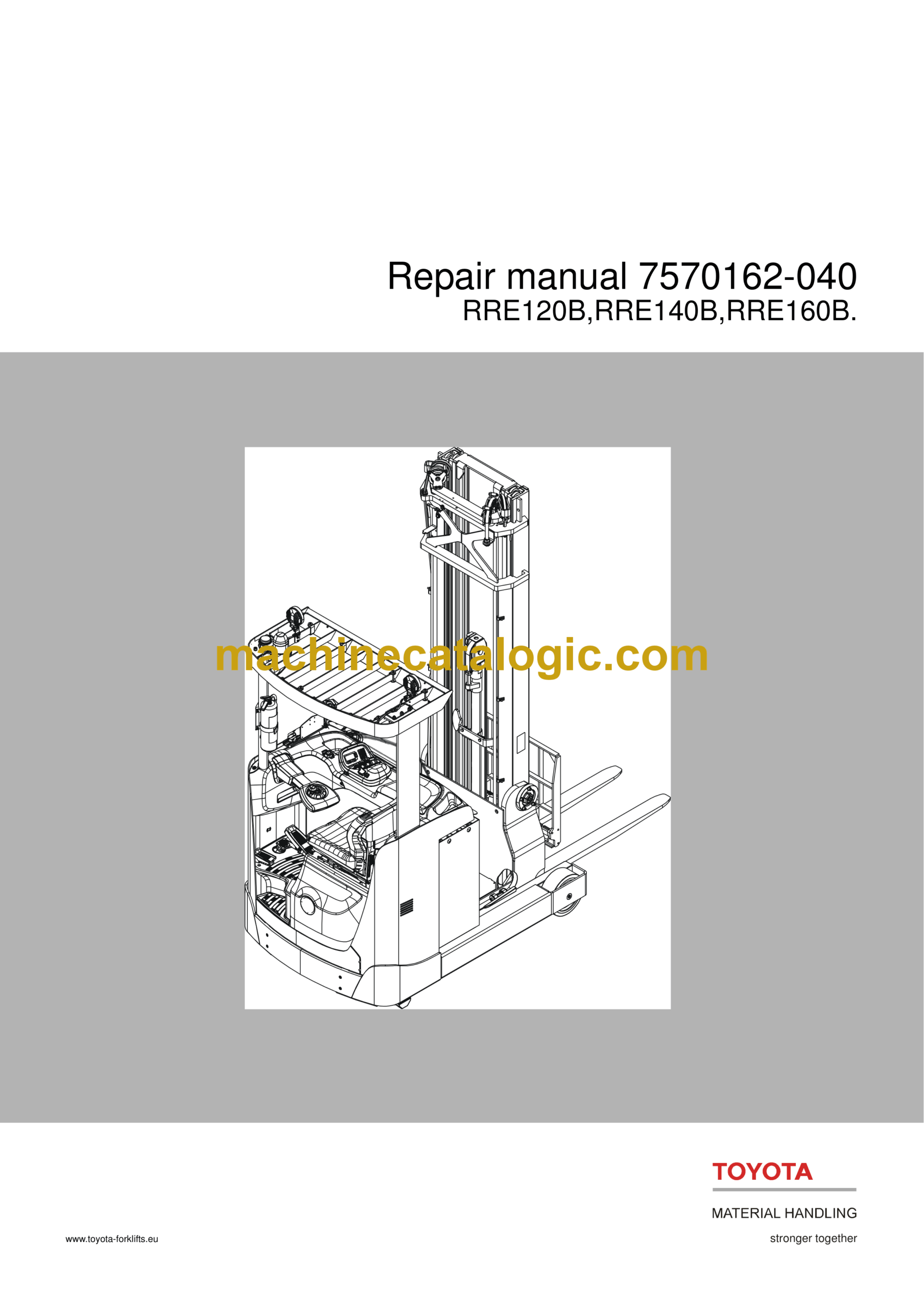
Model: RRE120B, RRE140B, RRE160B
Part No: 7570162-040
Type of Document: Repair Manual
$ 40
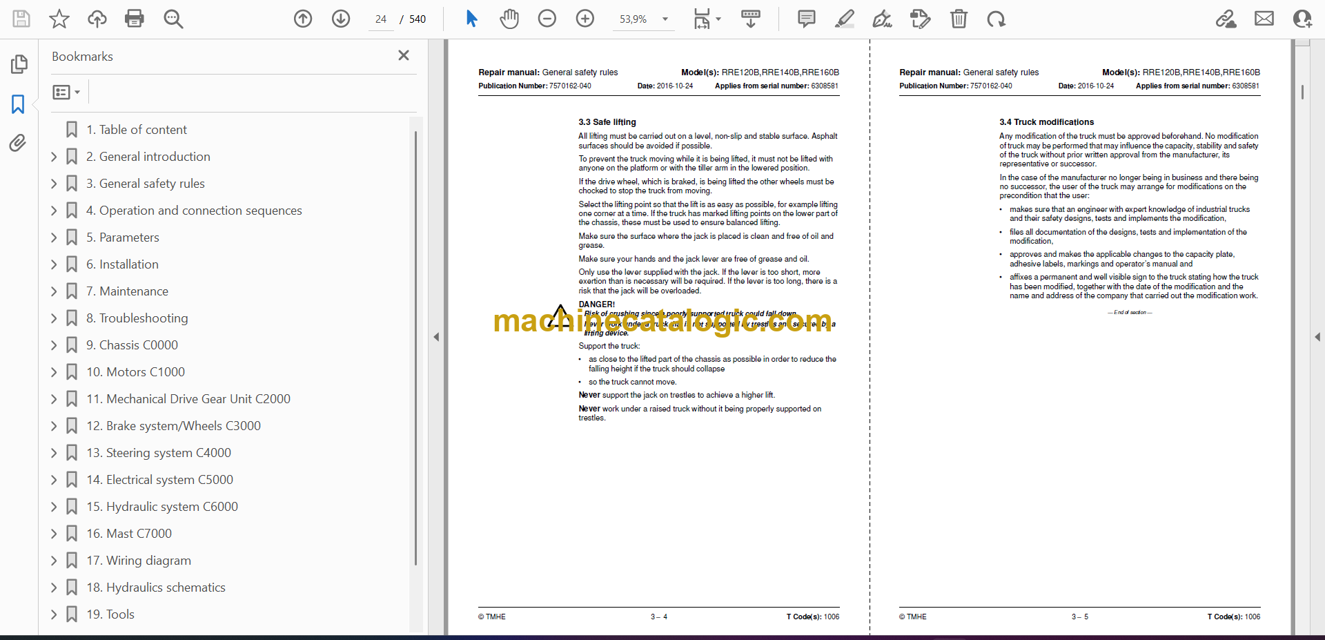
Table of content
2. General introduction
2.1 How to use this manual
2.2 Abbreviations
2.3 Warning symbols
2.4 Pictograms
3. General safety rules
3.1 Work safety
3.2 Electrical system
3.3 Safe lifting
3.4 Truck modifications
4. Operation and connection sequences
4.1 Description
5. Parameters
5.1 General
5.2 Parameter settings
5.3 Operator parameters
5.4 Service parameters
5.5 Factory parameters
6. Installation
6.1 Transporting the truck
6.2 Transporting the mast
6.3 Transporting the truck
6.4 Taking into operation
6.5 Dismantling the mast
6.6 Putting into operation.
7. Maintenance
7.1 Introduction
7.2 Safety precautions for maintenance work
7.3 Maintenance instructions
7.4 Symbols
7.5 CCrack detection
7.6 Safety checks
7.7 Periodic maintenance
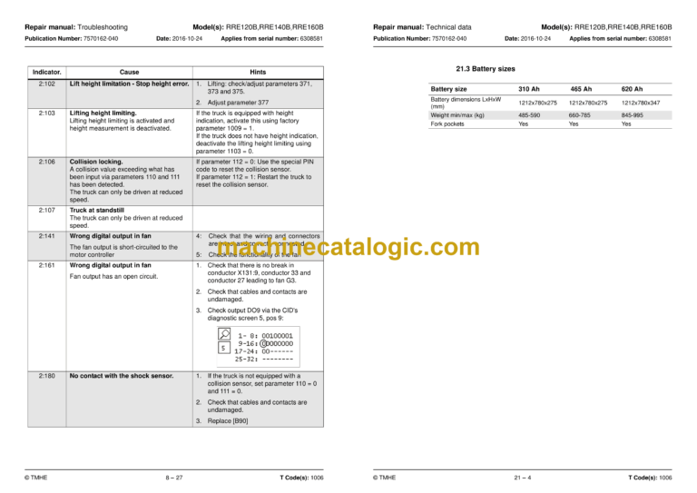
8. Troubleshooting
8.1 Auxiliary functions
8.2 Initial troubleshooting
8.3 Troubleshooting using blocking symbol
8.4 Troubleshooting using error codes
8.5 Troubleshooting without indications
9. Chassis C0000
9.1 Overview
9.2 Description
9.3 Floor C0330
9.4 Support arm C0350
9.5 Battery compartment parts C0390
9.6 Operator’s seat C0620
9.7 Operator controls C0640
9.8 Interior fittings C0680
9.9 Mirrors C0740
9.10 Overhead guard/Roof C0810
9.11 Finger-foot guard C0820
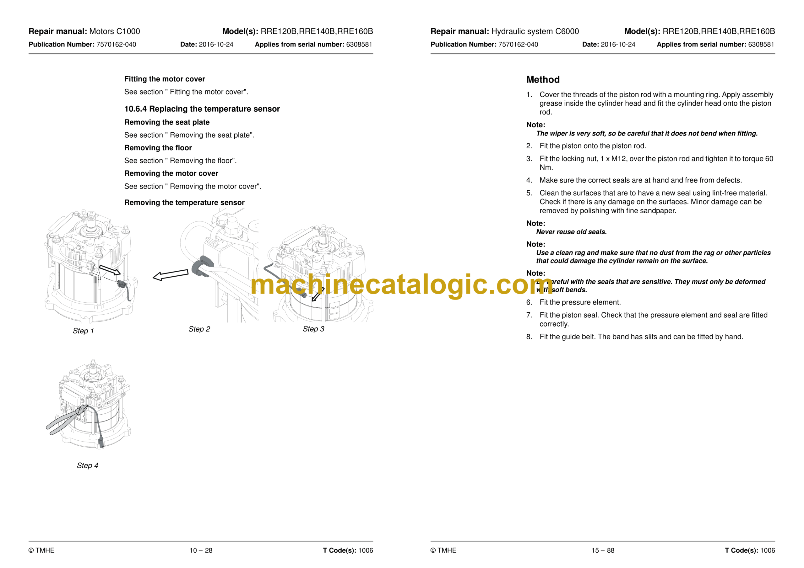
10. Motors C1000
10.1 Overview
10.2 Description
10.3 Electric pump motor C1710
10.4 Steering motor C1730
10.5 Electric fan motor / fan
10.6 Electric drive motor C1760
11. Mechanical Drive Gear Unit C2000
11.1 Overview
11.2 Description
11.3 Checking the oil level
11.4 Oil change
11.5 Leakage from the lower cover
11.6 Replacing the drive gear
11.7 Replacing the Steering bearings
12. Brake system/Wheels C3000
12.1 Brake system C3100
12.2 Parking brake C3370
12.3 Wheels C3500
12.4 Drive wheel C3530
12.5 Support arm wheel C3550
13. Steering system C4000
13.1 Description
13.2 Electric steering wheel C4310
13.3 Steering unit C4330
13.4 Steering reference sensor (4350)
14. Electrical system C5000
14.1 Description
14.2 OTP
14.3 Battery C5110
14.4 Signal / Alarm (Sound-light) C5160
14.5 Main contactor C5190
14.6 Instrument panel C5200
14.7 Height indication
14.8 Travel function wiring/ fuse C5390
14.9 Drive motor cables/resistor/fuse C5430
14.10 Transistor panel C5460
14.11 Work function harnesses / fuse C5590
14.12 Main processor – MCU C5710
14.13 Sending units and sensors C5800
14.14 Safety sensor / – sensors C5830
14.15 Height measurement system
14.16 Calibration
15. Hydraulic system C6000
15.1 General
15.2 Hydraulic hygiene
15.3 Bleeding the air from the hydraulic system
15.4 Hose inspection
15.5 Hydraulic couplings C6230
15.6 Hydraulic unit C6100
15.7 Hydraulic pump C6140
15.8 Main valve unit C6210
15.9 Control valve C6220
15.10 Chassis-mounted hydraulic hoses C6230
15.11 Mast hydraulic conduits C6320
15.12 Main lift cylinder C6610
15.13 Free lift cylinder C6620
15.14 Reach/telescopic cylinder C6650
15.15 Dismantling the cylinder
15.16 Tilting cylinder C6660
15.17 Sideshift cylinder C6670
15.18 Dismantling the cylinder
16. Mast C7000
16.1 Description
16.2 Installing a mast in a newly delivered truck
16.3 Main mast C7100
16.4 Main lifting chain system C7120
16.5 Fork carriage C7130
16.6 Main mast suspension C7190
16.7 Forks C7410
17. Wiring diagram
17.1 Component list
17.2 Component location
17.3 Connections
17.4 General wiring diagram
17.5 Detailed diagrams
18. Hydraulics schematics
18.1 Component list
18.2 Component location
18.3 Valve unit
18.4 Hydraulics schematics
19. Tools
19.1 AMP connectors
19.2 MQS contacts
19.3 CPC contacts
19.4 Other tools
20. Service data and grease specifications
20.1 General tightening torques
20.2 Oil and grease specification
21. Technical data
21.1 Mast type and weight (kg)
21.2 IP classes on components and units
21.3 Battery sizes
21.4 Truck dimensions


