Format: PDF (Printable Document)
File Language: English
File Pages: 64
File Size: 4.99 MB (Speed Download Link)
Brand: BT
Model: S12S
Part No: 570989AA-
Type of Document: Operators Manual
$ 40
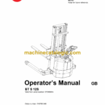
BT S 12S
Valid from serial number: 570989AA-
Order number: 210799-040
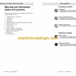
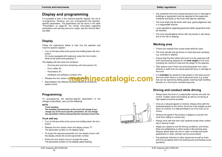
Safety regulations
Warning symbols
General safety regulations
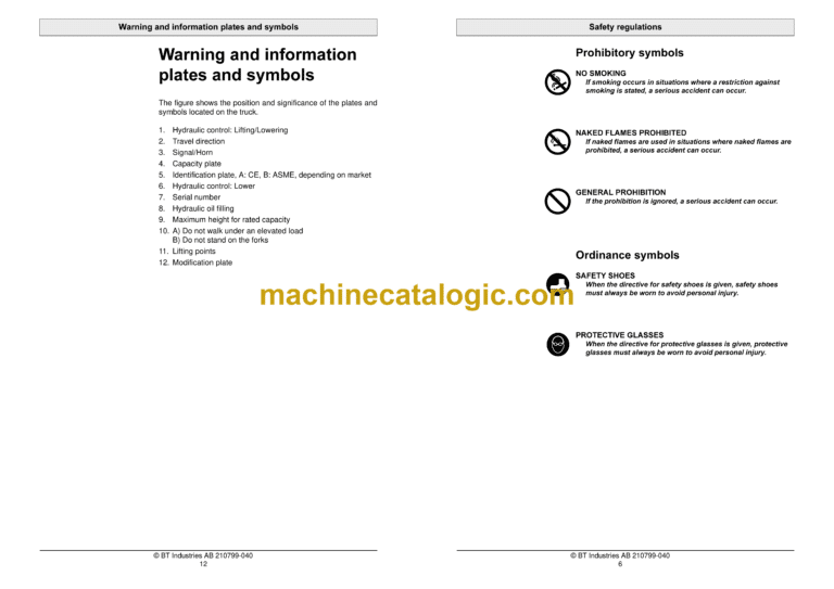
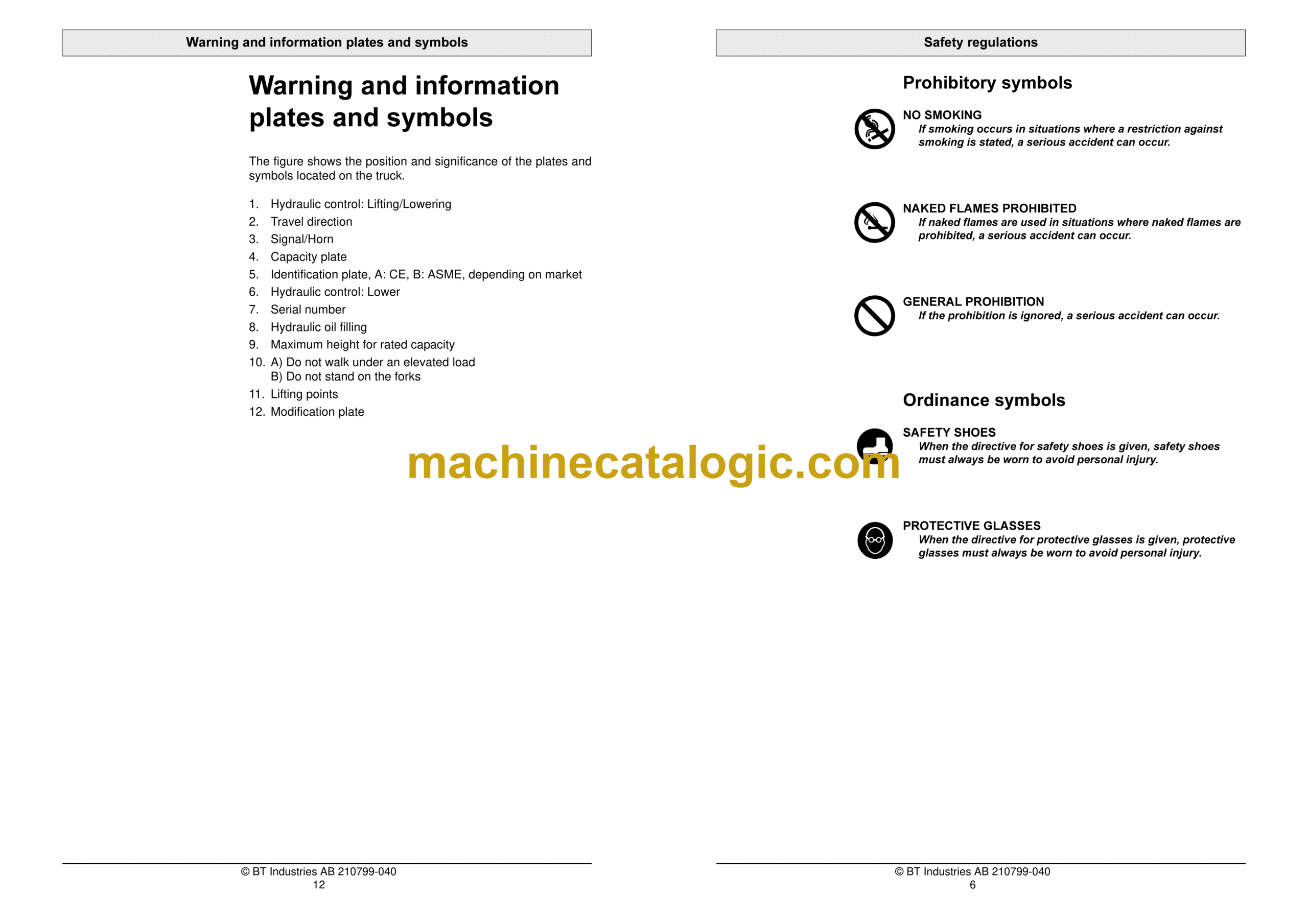
Warning and information plates and symbols
1. Hydraulic control: Lifting/Lowering
2. Travel direction
3. Signal/Horn
4. Capacity plate
5. Identification plate, A: CE, B: ASME, depending on market
6. Hydraulic control: Lower
7. Serial number
8. Hydraulic oil filling
9. Maximum height for rated capacity
10. A) Do not walk under an elevated load B) Do not stand on the forks
11. Lifting points
12. Modification plate
Presentation of the truck
Intended application of the truck
Forbidden application of the truck
Truck data
Truck dimensions
Identification plate
Capacity plate
Modification plate
Main components
1. Tiller arm: The truck is manoeuvred by the driver while walking. 204 degree steering area. The…
2. Identification plate: With model designation, serial number, year of manufacture, weight witho…
3. Covers: Removable which provides good accessibility when servicing.
4. Emergency switch off
5. Hydraulic control: For controlling lifting and lowering functions.
6. Hydraulic unit: Pump motor, pump and oil tank are integrated in a compact unit.
7. Hydraulic valves: The valves are located to provide easy access.
8. Drive unit with brake: Fixed drive unit with spring-loaded mechanical brake, travel motor, gea…
9. Serial number: The serial number plate fitted to the chassis.
10. Electric panel: Removable, which provides good access when servicing. 24 volt electrical supp…
11. Support castor wheels: Two support castor wheels to ensure stability.
12. Battery: 24V with different Ah values. The battery is automatically locked in the battery com…
13. Emergency disconnector and battery connector: The battery is charged via the permanently fitt…
14. Mast: Fitted with a finger guard to cover the driver’s normal reach.
15. Support arms:
Controls and instruments
1. Control for lifting and lowering the forks
2. Travel direction selector and speed control
3. Switch for safety reversing
4. Horn
5. Display
6. Tiller arm and brake
7. Control for lowering the forks
8. Emergency switch off
9. Key switch
10. Emergency disconnector and battery connector
11. Turtle button (Option)
12. Keyboard (Option)
Control for lifting and lowering the forks (1)
Travel direction selector and speed control (2)
Switch for safety reversing (3)
Horn (4)
Display (5)
Function
Tiller arm and brake (6)
Control for lowering the forks (7)
Emergency switch off (8)
Key switch (9)
Emergency disconnector and battery connector (10)
Turtle button (11) (Option)
Keyboard (12) (Option)
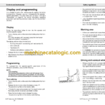
Display and programming
Warning codes
Error codes
Accessories
Platform
Load support
Integrated charger
Turtle button
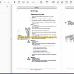
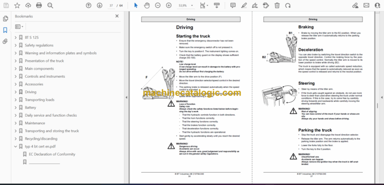
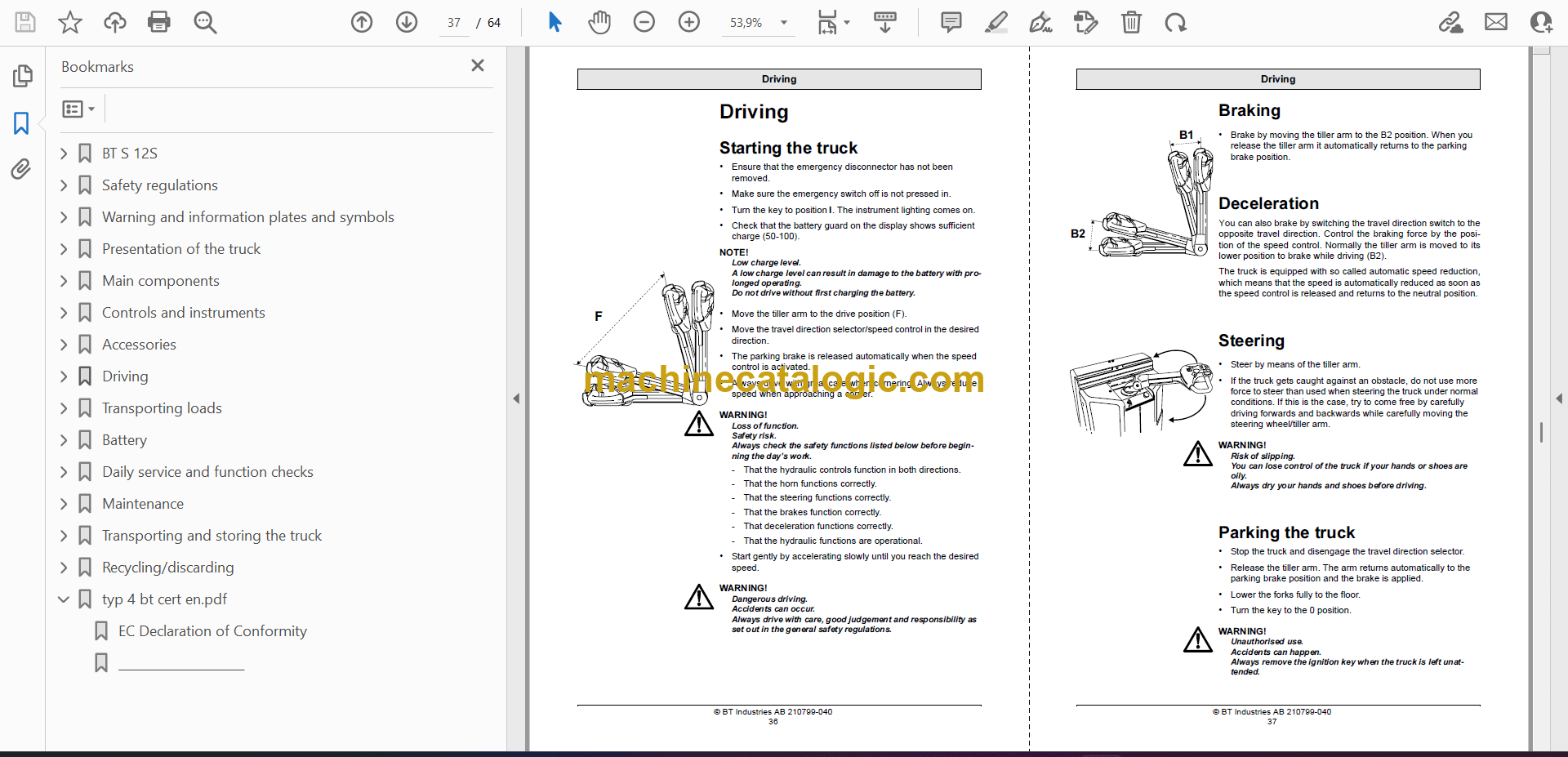
Driving
Starting the truck
Braking
Deceleration
Steering
Parking the truck
Transporting loads
WARNING!
WARNING!
WARNING!
WARNING!
WARNING
WARNING!
WARNING!
Collecting a load
Depositing a load
Lift height limiting ASME
Battery
Changing the battery
Charging the battery
Battery maintenance
Daily service and function checks
WARNING!
Pos no
Check points
Action
Maintenance
Safety regulations with maintenance work
Maintenance work that is to be carried out by the operator
Maintenance work that may be carried out by trained maintenance personnel
Cleaning and washing
Maintenance chart
Lubrication chart
Oil and grease specification
Transporting and storing the truck
The truck’s dimensions and weight as standard
Lifting the truck
Towing and transporting a defective truck
Storing the truck
Starting after a period of disuse
Recycling/discarding
Discarding the battery
Scrapping the truck
typ 4 bt cert en.pdf
EC Declaration of Conformity
