Format: PDF (Printable Document)
File Language: English
File Pages: 196
File Size: 9.15 MB (Speed Download Link)
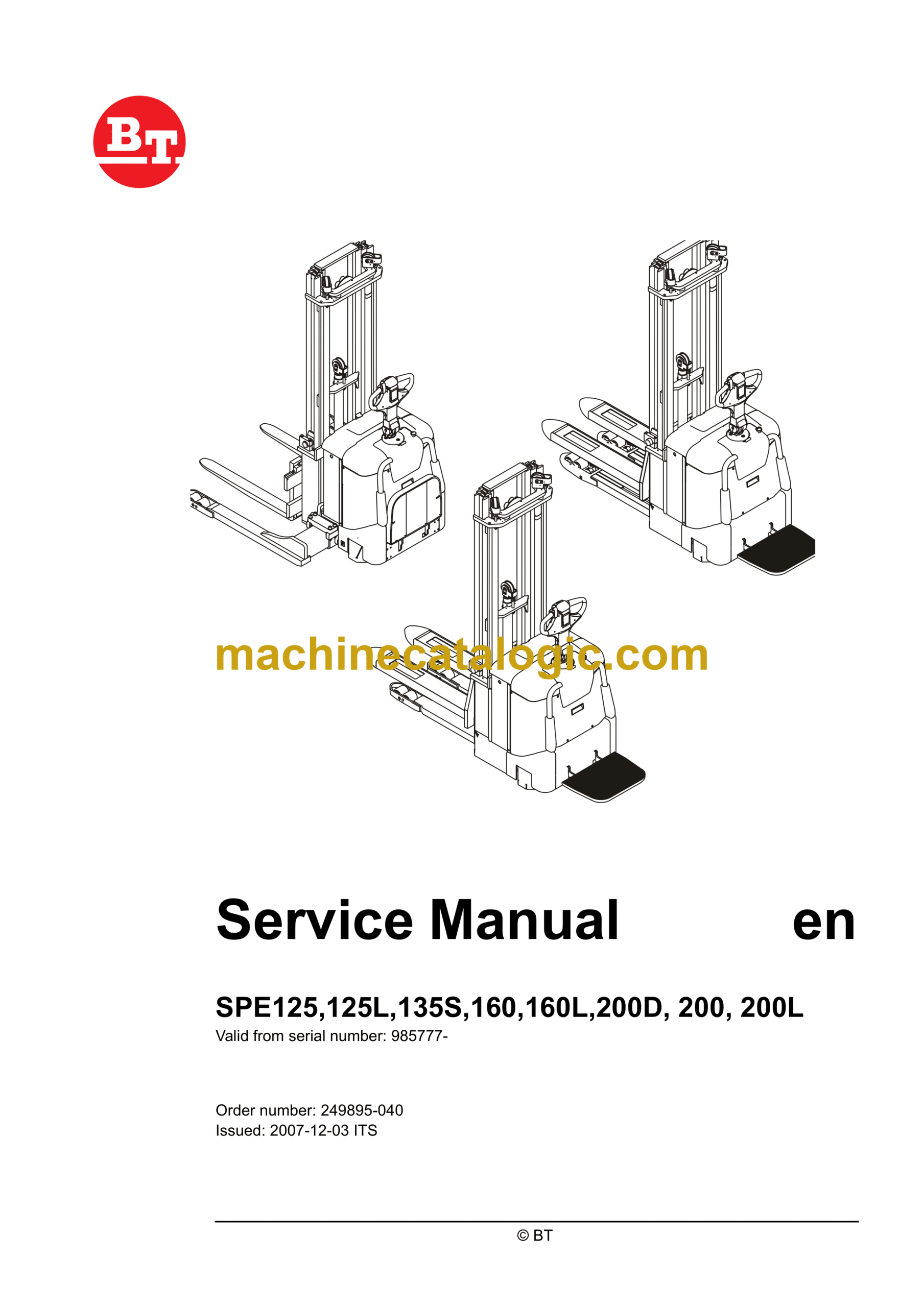
Brand: BT
Model: SPE125, SPE125L, SPE135S, SPE160, SPE160L, SPE200D, SPE200, SPE200L Electric Stacker
Part No: 985777-
Type of Document: Master Service Manual
$ 40
1- Table of contents
2- Technical data
2.1 General tightening torques
3- Maintenance
3.1 Safety rules during maintenance work
3.2 Special safety instructions for trucks with a roller bed for a battery
3.3 Cleaning and washing
3.4 Safe lifting
3.5 Lifting the truck
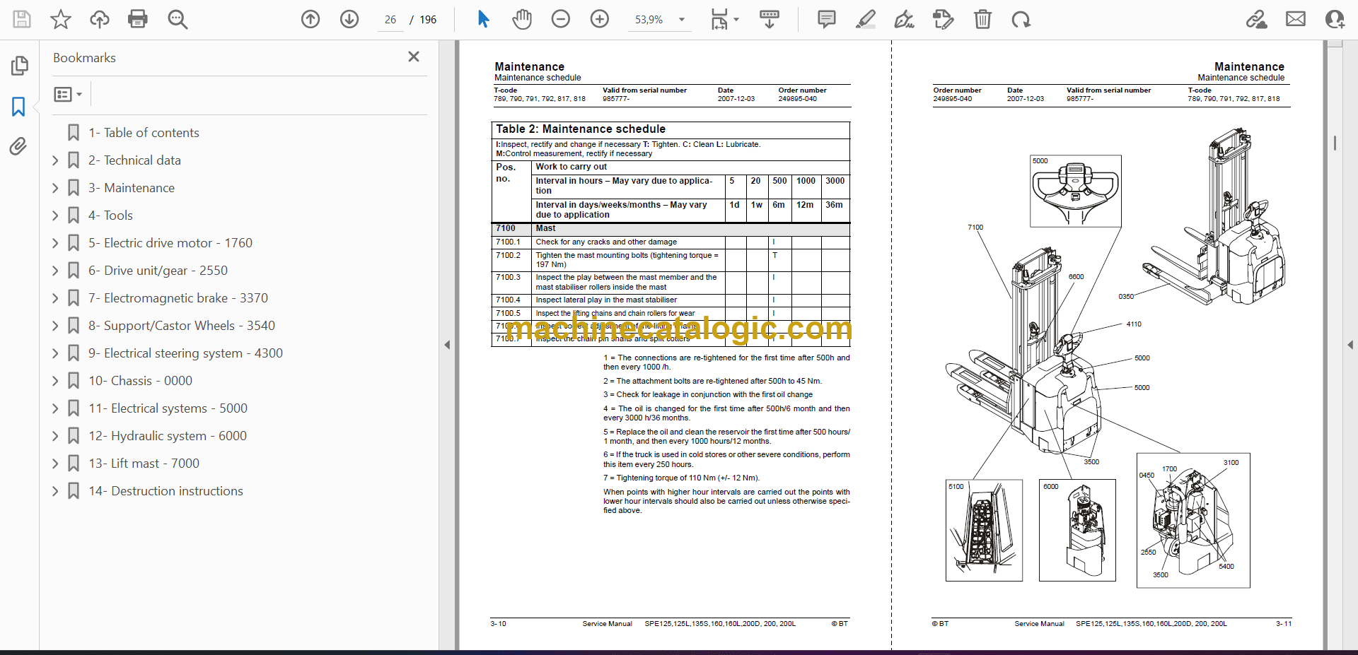
3.6 Maintenance schedule
3.7 Lubrication chart
3.8 Oil and grease specification
4- Tools
4.1 Super Seal connectors
4.2 AMP connectors
4.3 Molex connectors
4.4 Grease guns
4.5 Other tools
5- Electric drive motor – 1760
5.1 Included components
5.2 Disassembly/assembly of the truck motor
5.3 Service/repairs
6- Drive unit/gear – 2550
6.1 General
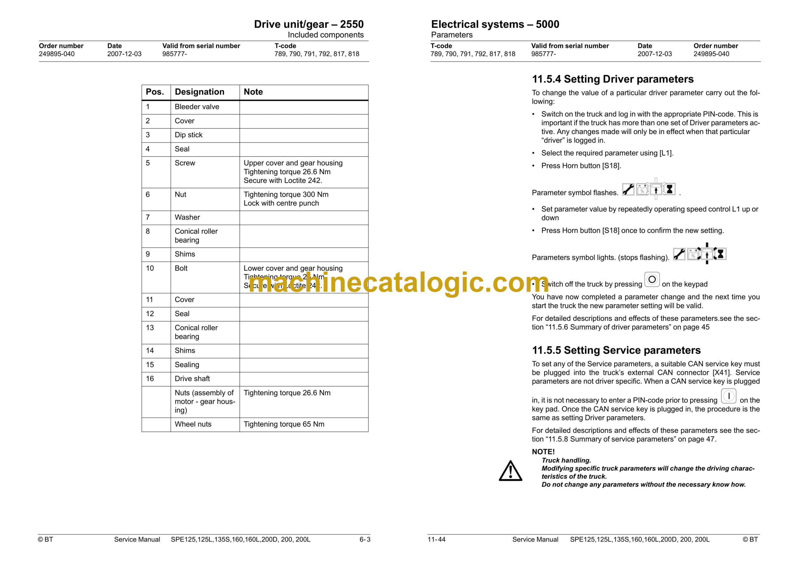
6.2 Included components
6.3 Disassembly of the drive unit from the truck
6.4 Assembly of the drive unit in the truck
6.5 Oil inspection or changing oil
6.6 Replacing the gasket ring
6.7 Leakage from top cover
7- Electromagnetic brake – 3370
7.1 Main components of the brake
7.2 Maintenance
8- Support/Castor Wheels – 3540
8.1 Tightening torque
9- Electrical steering system – 4300
9.1 Electrical steering servo
9.2 Steering servo components
9.3 Adjustment
10- Chassis – 0000
10.1 Support arms
10.2 Engine suspension
10.3 Platform
11- Electrical systems – 5000
11.1 General
11.2 Electrical equipment overview
11.3 Electrical wiring diagram
11.4 Functional description
11.5 Parameters
11.6 Diagnostic and troubleshooting
11.7 Technical specifications – Curtis 1243
12- Hydraulic system – 6000
12.1 Hydraulic diagram
12.2 Main Components
12.3 Description
13- Lift mast – 7000
13.1 Mast incline
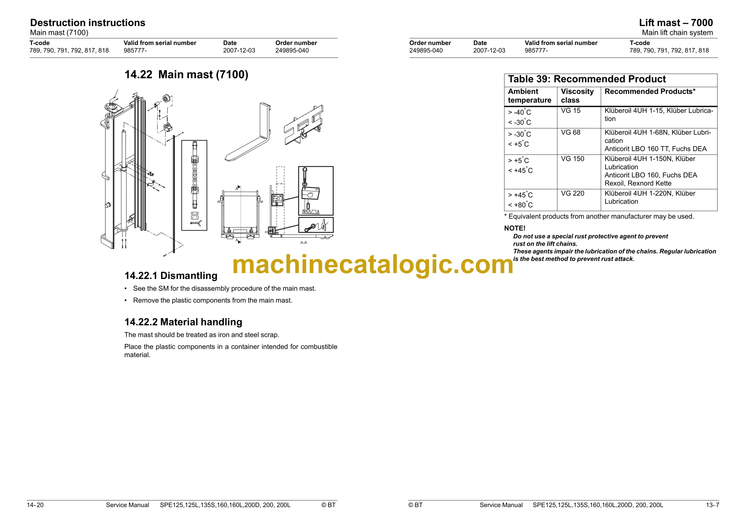
13.2 Main lift chain system
14- Destruction instructions
14.1 General
14.2 Procedure
14.3 Abbreviations
14.4 Sorting
14.5 Chassis (0300)
14.6 Hoods, covers (0340)
14.7 Fork structure (low-lifter) (0380)
14.8 Travel platform including mount (0560)
14.9 Overhead guard (option) (0810)
14.10 Operator protective device (0840)
14.11 Electric pump motor (1710)
14.12 Electric travel drive motor (1760)
14.13 Drive unit/gear (2550)
14.14 Wheels (3500)
14.15 Steering arm (4110)
14.16 Steering arm (4110)
14.17 General electric equipment (5100)
14.18 Cabling (5590)
14.19 Steering and protective electronics (5700)
14.20 Lift/lowering sensor (5820) and safety sensor (5830)
14.21 Hydraulic unit (6100)
14.22 Main mast (7100)
14.23 Chassis-mounted hydraulic oil lines (6230) (and main lift cylinder (6610))
14.24 Battery charger connector (9380)


