Format: PDF (Printable Document)
File Language: English
File Pages: 262
File Size: 26.61 MB (Speed Download Link)
Brand: BT
Model: VCE150A, 150AC, 125ASF, 125ACSF C15
Part No: 227761-040 and 919699-
Type of Document: Master Service Manual
$ 40
1- Contents
2- Preventive maintenance – P2 (T code 712)
3- Preventive maintenance – P2 (T code 713)
4- Oil and grease specifications – P3 (T code 712)
5- Oil and grease specification – P3 (T code 713)
6- Tools – P4
6.1 Super Seal contact
7- Chassis – 0000 Truck installation
7.1 General
7.2 Tool list
7.3 Unloading the truck
7.4 Preparations for commissioning
7.5 Installation in narrow aisle
7.6 Removal/reassembly of rear chassis, including bearings
7.7 Replace the pivot bearings
7.8 Battery locking device
8- Frame pivot – 0320
8.1 Greasable axle
9- General tightening torque – 0400
9.0.1 Galvanised, non-oiled bolts
9.0.2 Untreated, oiled bolts
9.1 Tightening torque
10- Electric pump motor – 1710.1
10.1 General
10.2 Disassembled pump motor
10.3 Disassembly and assembly of the pump motor
10.4 Replacing the ball bearing
10.5 Assembly instruction for the external temperature sensor
11- Electric pump motor – 1710.2
11.1 General
11.2 Disassembled pump motor
11.3 Disassembly and assembly of the pump motor
11.4 Replacing the ball bearing
12- Electric drive motor – 1760
12.1 General
12.2 Disassembled drive motor
12.3 Disassembly and assembly of the drive motor
12.4 Replacing the ball bearing
12.5 Assembly instructions for the external temperature sensor
13- Drive unit/gear – 2550
13.1 General
13.2 Components/data of the drive unit and gear
13.3 Replacing the drive motor/drive gear
13.4 Oil level check/replacement
13.5 Repairs
14- Service brake system – 3100.1
14.1 General
14.2 Functional description
14.3 Electromechanical disc brake, drive motor
14.4 Maintenance
14.5 Disc brake with multiple discs, support arms
14.6 Maintenance
15- Service brake system – 3100.2
15.0.1 General
15.0.2 Functional description
15.0.3 Releasing the accelerator pedal
15.0.4 Travel direction selector
15.0.5 Depressing the brake button
15.0.6 Parking brake
15.0.7 Emergency braking
15.0.8 Electromechanical disc brake, drive motor
15.0.9 Dismantling
15.0.10 Inspection
15.0.11 Assembly
15.0.12 Maintenance
15.0.13 Adjustment of play
15.0.14 Wear
15.0.15 Inspect the braking force
15.0.16 Disc brake with multiple discs, support arms
15.0.17 Assembly
15.0.18 Dismantling
15.0.19 Inspection
15.0.20 Assembly
15.0.21 Maintenance
15.0.22 Adjustment of play
16- Support arm brake – 3180
16.1 Location of support arm brake
17- Drive wheel – 3530
17.1 General
17.2 Dismantling the drive wheel
17.3 Assembling the drive wheel
18- Fork/support arm wheel – 3550
18.1 Dismantling the wheel
18.2 Assembling the wheel
18.3 Dismantling/assembling the wheel bearings
18.4 Support arm wheel axle
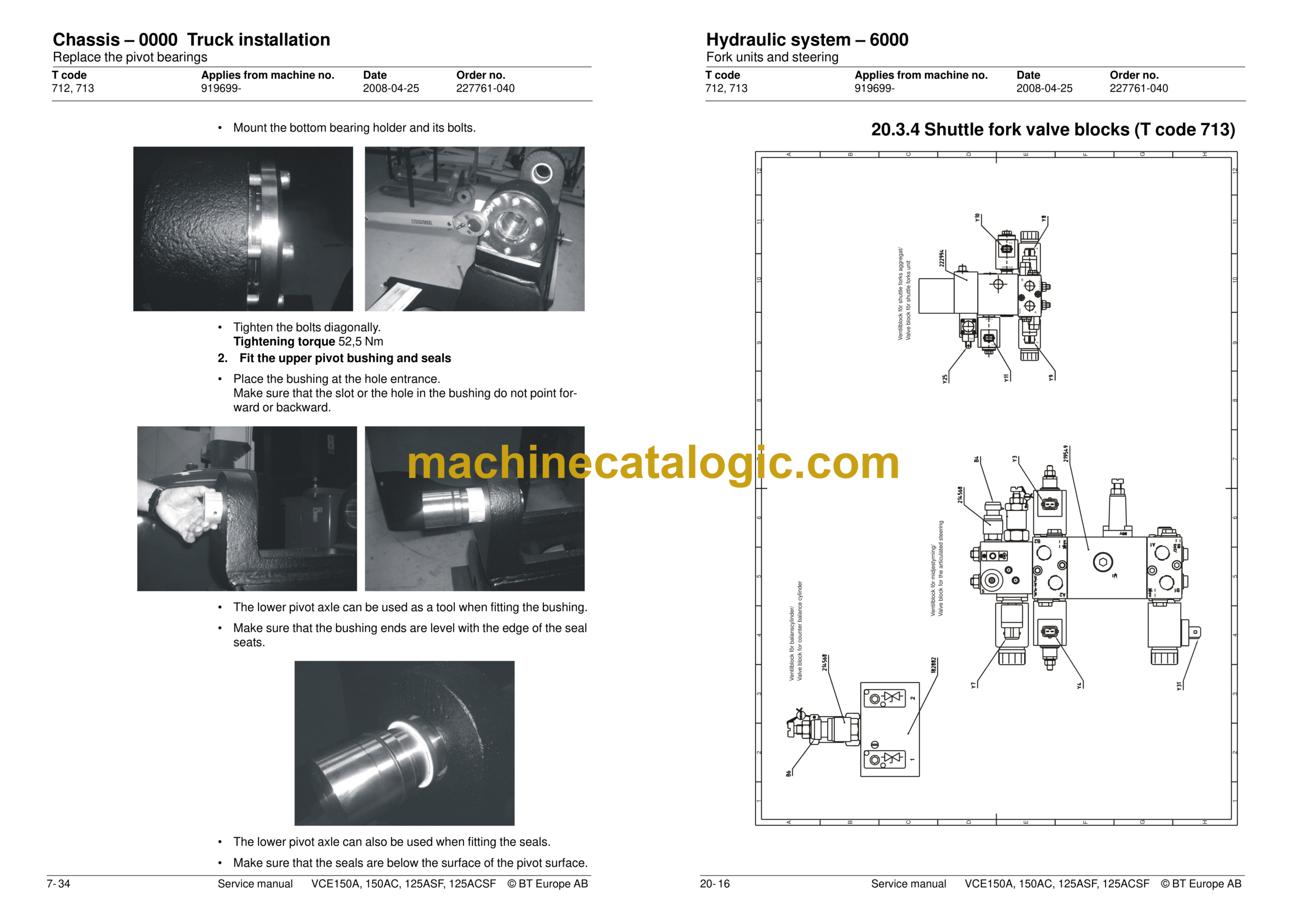
20- Hydraulic system – 6000
20.1 General
20.2 Cabin lifting
20.3 Fork units and steering
20.4 Extra hydraulic function (T code 712)
21- Hydraulic pump – 6140
21.1 General
21.2 Replacing the hydraulic pump
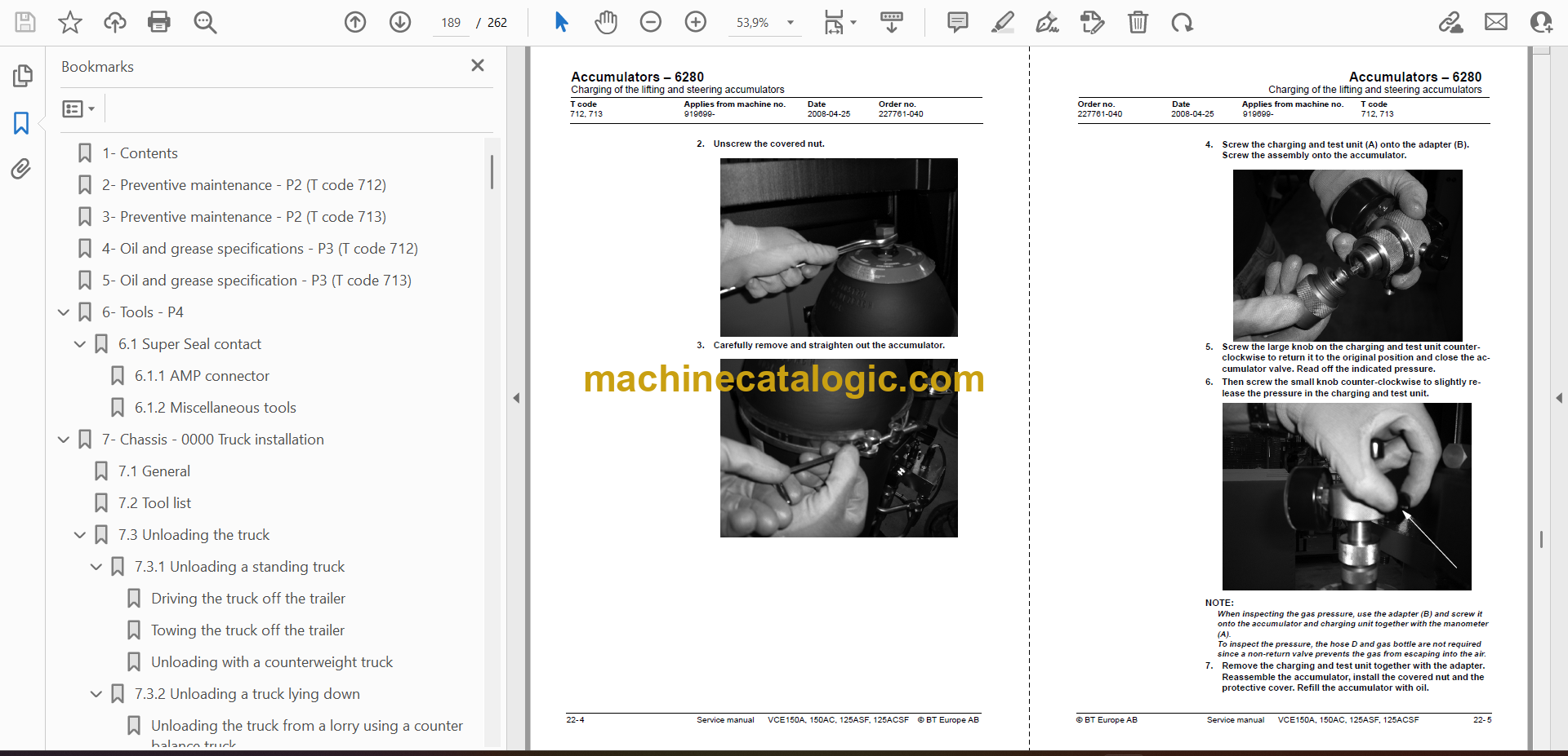
22- Accumulators – 6280
22.1 Charging of the lifting and steering accumulators
22.2 Measuring the pressure in the steering accumulator
23- Main lift cylinder – 6610
23.1 Replacing the seal in the B cylinder
24- Main mast and mast – 7100
24.1 Setting the cab and mast stoppers
25- Main lift chain system – 7120
25.1 General
25.2 Checking the chain setting
25.3 Chain inspection
25.4 Cleaning
25.5 Lubrication
25.10 Initial mast – 7160
26- Initial mast/Turret head fork unit – 7200 (T code 712)
26.1 General
26.2 Assembly/disassembly of the initial mast
26.3 Inspection and replacement of belts used for fork traversing
26.4 Friction plate adjustment
26.5 Parallel adjustment of forks
27- Shuttle fork – 7800 (T code 713)
27.1 Assembly of the shuttle fork
27.2 Maintenance
27.3 Replacing the shuttle forks
27.4 Shuttle fork unit – 7800
28- Wire guidance equipment – 8200
28.1 General
28.2 Generator
29- Height preselection – 9390
29.1 General
29.2 Parameters
29.3 Programming


