Format: PDF (Printable Document)
File Language: English
File Pages: 1132
File Size: 124.95 MB (Speed Download Link)
Brand: BT
Model: VRE125, VRE150, VRE125SF
Part No: 7549080-040
Type of Document: Repair Manual
$ 40
1. Contents
2. General introduction
2.1 How to use the manual
2.2 Warning symbols
2.3 Abbreviations
2.4 Pictograms
3. General safety precautions
3.1 Work safety
3.2 Electrical systems
3.3 Safe lifting
4. Chassis C0000
4.1 Inspection covers C0340
4.2 Battery compartment parts C0390
4.3 Operator’s cab C0500
4.4 Cab windows C0530
4.5 Cab door C0550
4.6 Operator’s seat C0620
4.7 Cab heating/ventilation C0630
4.8 Driver controls (mechanical) C0640
4.9 Mirrors C0740
4.10 Overhead guard/roof C0810
4.11 Finger/foot guards C0820
4.12 Operator protection C0840
4.13 Signs, warnings, labels C0850
5. Motors C1000
5.1 Electric pump motor C1710
5.2 Electric steering motor C1730 (steering servo assembly)
5.3 Electric fan motor/fan C1740
5.4 Electric drive motor C1760
6. Drive gear C2000
7. Brake system/Wheels C3000
7.1 Brake system C3100
7.2 Wheel C3500
8. Steering system C4000
8.1 Electric steering wheel C4310
8.2 Steering unit C4330
8.3 Steering angle reference sensor C4350
8.4 Steering bearing C4380
8.5 Wire guidance C4510
8.6 Rail guidance C4510
8.7 Wire guidance, antenna C4540
9. Electrical system C5000
9.1 Battery C5110
9.2 General alarm signals (audible/visual)
9.3 Main contactor [Q10] C5190
9.4 Instrument panel C5200
9.5 Weighing system
9.6 Overload limit
9.7 Height measurement system
9.8 Height preselector (option)
9.9 Transistor panel C5460
9.10 Work function harnesses/fuse C5590
9.11 Main processor – MCU C5710
9.12 Fork control unit – FCU C5720
9.13 Expansion unit – GFU C5730
9.14 Sending units and sensors C5800
9.15 Safety probes/sensors C5830
9.16 Narrow aisle sensor C5840
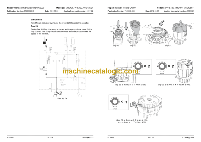
10. Hydraulic system C6000
10.1 Hydraulic unit C6100
10.2 Main valve unit C6210
10.3 Mast valve units C6310
10.4 Calibration of proportional valves
10.5 Hydraulic cylinders C6600
10.6 Filtering the hydraulic oil
10.7 Pressure relief
11. Mast C7000
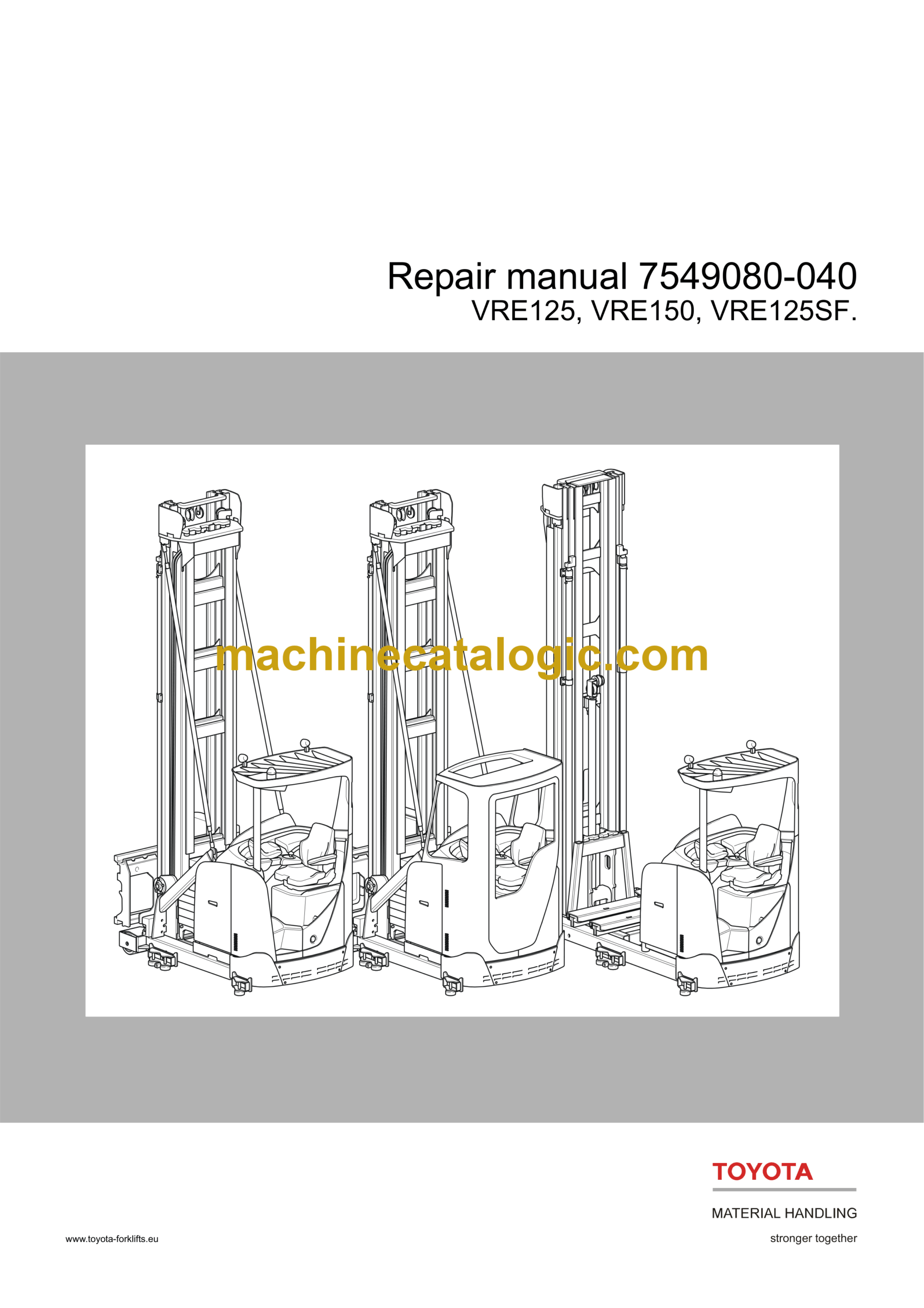
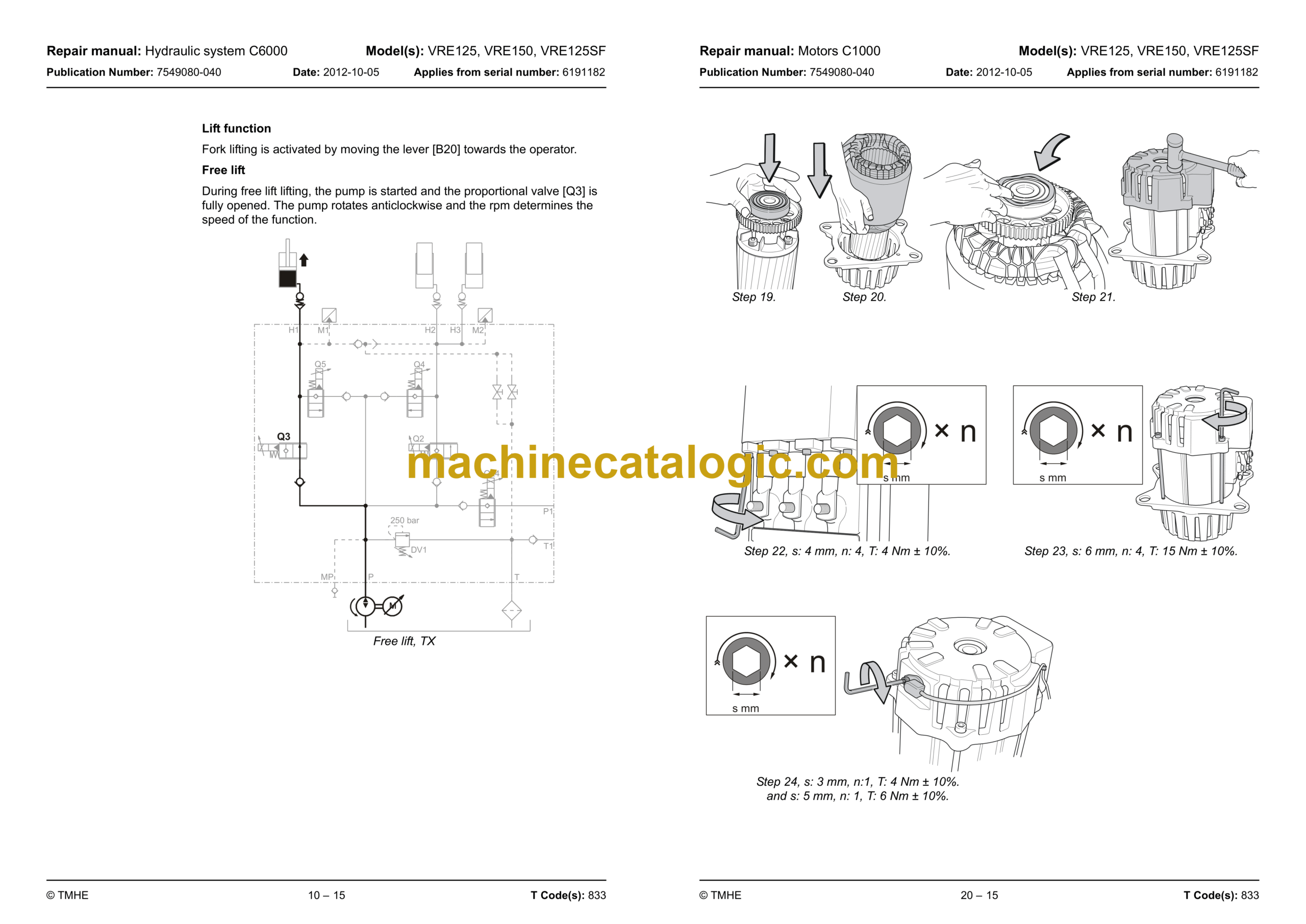
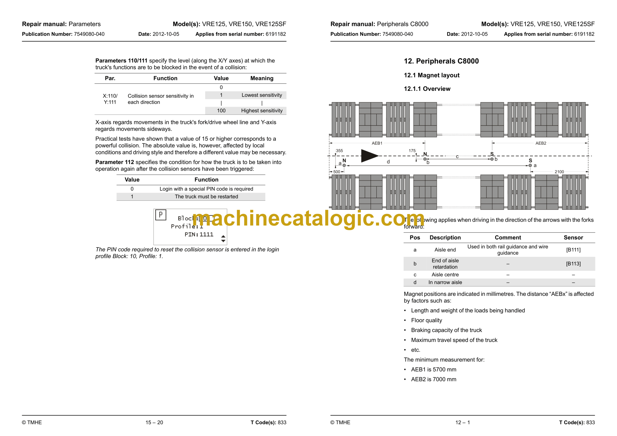
12. Peripherals C8000
12.1 Magnet layout
12.2 Photocell layout
13. Options/Extra equipment C9000
13.1 Extra electrical equipment C9300
13.2 Radio equipment C9330
13.3 Extra lighting C9360
13.4 Extra warning lights/alarm C9370
13.5 Positioning/TV equipment C9390
13.6 Extra electrical equipment C9400
13.7 Truck log equipment, code lock C9420
13.8 Other extra equipment C9500
14. Operation and connection sequences
14.1 Battery is connected
15. Parameters
15.1 General
15.2 Parameter settings
15.3 Operator parameters
15.4 General service parameters
15.5 Service parameters, travel functions
15.6 Service parameters, hydraulics
15.7 Service parameters, CID
15.8 Service parameters, VNA
15.9 Service parameters, FCU
15.10 General factory parameters
15.11 Factory parameters, narrow aisle
15.12 Factory parameters, activation of options
15.13 Factory parameters, calibration
16. Installation
16.1 Initial setup
17. Maintenance
17.1 Introduction
17.2 Safety precautions for maintenance work
17.3 Maintenance instructions
17.4 Oil and grease specification
17.5 Symbols
17.6 Safety check
17.7 Periodic maintenance
18. Troubleshooting
18.1 Auxiliary functions
18.2 Initial troubleshooting
18.3 Troubleshooting using blocking symbol
18.4 Troubleshooting using error codes
18.5 Troubleshooting without a fault code
19. Chassis C0000
19.1 Inspection covers C0340
19.2 Installing counterbalance C0370
19.3 Cab windows C0530
19.4 Cab door C0550
19.5 Operator’s seat C0620
19.6 Cab heating/ventilation C0630
19.7 Operator controls (mechanical) C0640
19.8 Overhead guard/roof C0810
19.9 Finger/foot guards C0820
19.10 Operator protection C0840
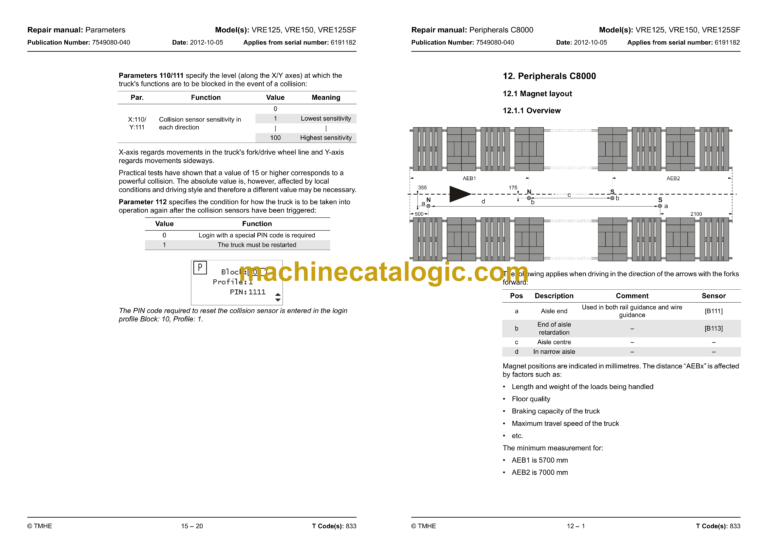
20. Motors C1000
20.1 Electric pump motor C1710
20.2 Electric steering motor C1730
20.3 Electric fan motor/fan C1740
20.4 Electric drive motor C1760
21. Drive gear C2000
21.1 Mechanical drive gear unit
22. Brake system/Wheels C3000
22.1 Support arm brake C3180
22.2 Parking brake C3370
22.3 Emergency brake release
22.4 Wheel C3500
22.5 Drive wheel C3530
22.6 Support arm wheel C3550
22.7 Side guide wheel C3580 (option)
23. Steering system C4000
23.1 Electric steering wheel C4310
23.2 Steering angle reference sensor C4350
23.3 Steering bearing C4380
24. Electrical system C5000
24.1 Battery C5110
24.2 Main contactor C5190
24.3 Instrument panel C5200
24.4 Drive motor cables/resistors/fuses C5430
24.5 Transistor panel C5460
24.6 Work function harnesses/fuse C5590
24.7 Main processor – MCU C5710
24.8 Fork control unit – FCU C5720
24.9 Safety probes/sensors C5830
24.10 Calibrations
25. Hydraulic system C6000
25.1 Hydraulic hygiene
25.2 Hydraulic system, bleeding
25.3 Hose inspection
25.4 Quick change connector
25.5 Tank C6110
25.6 Filter C6130
25.7 Fork valve unit C6310
25.8 Hydraulic cylinders C6600
26. Mast C7000
26.1 Ordering a replacement mast
26.2 Adjusting/setting mast inclination on the truck
26.3 Main lifting chain system C1720
26.4 Forks C7410
26.5 Turret head fork unit C7700
26.6 Mast traversing function, fork unit C7710
26.7 Swivel/rotation function, fork unit C7720
26.8 Shuttle fork unit C7800
26.9 Shuttle fork power unit
27. Peripherals C8000
28. Option/Extra equipment C9000
29. Instructions for disposal
29.1 General
29.2 Marking of plastics
29.3 Pressure vessels
29.4 Sorting categories
30. Wiring diagram
30.1 Components
30.2 Component location
30.3 Cable connections and terminal posts
30.4 Fuse panel [A9]
30.5 Overview
30.6 Wiring diagrams
30.7 Wiring diagram CC
31. Hydraulics schematics
31.1 Main valve unit, VRE duplex
31.2 Main valve unit, VRE triplex
31.3 Fork valve unit, turret head/three-way fork unit 2 functions
31.4 Fork valve unit, turret head/three-way fork unit 3 functions
31.5 Fork valve unit, SF
31.6 Valve unit for tilt (Option)
31.7 List of symbols
31.8 Wiring diagrams
32. Tools
32.1 AMP contacts
32.2 MQS contacts
32.3 CPC contacts
32.4 Other tools
33. Service data and grease specifications
33.1 General tightening torques
33.2 Oil and grease specification
34. Technical data
34.1 Basic data
34.2 Mast type and weight (kg)
34.3 IP classes on components and units
34.4 Battery sizes
34.5 Truck dimensions

