Case C314X Mini Track Loader Operators Manual (92772267, B280201086) (January 2026)
Out on a construction site or a muddy landscape job, that Case C314X mini track loader’s gonna live in dirt, tight spaces, and half-finished grades. This operators manual helps you trace what every control actually does, how the machine reacts when you’re on a slope, in soft ground, or crowding a pile, and what to check before you turn the key. Say you’re loading trucks on a wet morning: the book walks you through how to set your travel speed, keep the load low, and avoid spinning tracks or nosing over at the ramp.
Applications & Use Cases
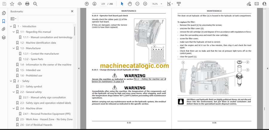
- Walk through start-up and shutdown so you don’t forget to release hydraulic pressure before you disconnect any quick couplers.
- Follow the daily inspection routine to check fluids, inspect tracks and rollers, and verify your safety switches actually work.
- Learn how to route your work: travel with a loaded bucket, keep the machine aligned on slopes, and avoid side-hilling that’ll get you in trouble.
- Use the control explanations to isolate whether a weird movement is operator error or something you really need a tech to test.
- Reference the attachment guidance so you match the right habits when you swap buckets, forks, or brooms and bleed off pressure safely.
FAQ
Q: Is this a PDF I can search on my phone or laptop?
A: Yes, it’s typically a searchable PDF, so you can jump to sections by keyword instead of flipping pages.
Q: Can I print just the pages I need for the jobsite?
A: You usually can; most folks print the safety, controls, and daily checks pages and keep them in a plastic sleeve in the cab or toolbox.
Safety Note
Always drop the attachment to the ground, kill the engine, and relieve hydraulic pressure before you inspect, bleed, or disconnect any hydraulic lines.
Case C314X Mini Track Loader Index:
- 1 - Introduction
- 1.1 – Regarding this manual
- 1.1.1 – Manual consultation and terminology
- 1.2 – Machine identification data
- 1.3 – Manufacturer
- 1.3.1 – Contact the manufacturer
- 1.3.2 – Spare Parts
- 1.4 – Information to the owner of the machine
- 1.5 – Intended use
- 1.6 – Prohibited use
- 2 - Safety
- 2.1 – Safety symbol
- 2.2 – General safety
- 2.2.1 – Manual safety sign consultation
- 2.3 – Safety signs and operation related labels
- 2.4 – Machine driver
- 2.4.1 – Personal Protective Equipment (PPE)
- 2.5 – Work Area – Hazard Zone – No Entry Zone
- 2.6 – List of Residual Hazards
- 2.7 – Safety procedures
- 2.8 – Safety devices
- 2.8.1 – Control cut-out button
- 2.8.2 – Parking brake button
- 2.8.3 – Operator presence sensor
- 2.8.4 – Emergency stop button
- 2.8.5 – High-voltage disconnect switch
- 2.8.6 – Reversing audible warning device
- 3 - Technical data
- 3.1 – General data
- 3.2 – Engine
- 3.3 – Power supply
- 3.4 – Battery charging times
- 3.5 – Electrical system
- 3.6 – Hydraulic system
- 3.7 – Performance
- 3.8 – Counterweight
- 3.9 – Undercarriage
- 3.9.1 – Translation motors
- 3.10 – Fluid capacities
- 3.11 – Brakes
- 3.12 – Operating load
- 3.12.1 – Bucket
- 3.12.2 – Pallet forks
- 3.13 – Overall dimensions
- 4 - Transporting the machine
- 4.1 – Transportation dimensions
- 4.2 – Loading/unloading operations
- 4.3 – Securing the machine on the mean of transport
- 4.4 – Lifting the machine
- 4.4.1 – Lifting procedure
- 4.5 – Recovering and pulling the machine
- 5 - Controls and instrumentation
- 5.1 – Description of controls
- 5.2 – Description of control levers
- 5.3 – Description of dashboard
- 5.4 – Roller operation
- 5.5 – Auxiliary power socket on console
- 5.6 – Control panel
- 5.7 – Display
- 5.8 – Battery disconnect switch (emergency stop button)
- 5.9 – myNewHollandConstruction portal and app
- 6 - Using the machine
- 6.1 – Commissioning
- 6.2 – Battery disconnect switch (emergency stop button)
- 6.3 – Driver seat
- 6.4 – Control cut-out button
- 6.5 – Parking brake button
- 6.6 – Control panel operation
- 6.6.1 – Dashboard to scroll through the menu on the display
- 6.7 – HOME page
- 6.7.1 – Time
- 6.7.2 – Machine hours
- 6.7.3 – Control mode
- 6.7.4 – Travel speed
- 6.7.5 – Engine data and battery data
- 6.7.6 – Pop-up messages (information/alarms)
- 6.7.7 – Warning indicators
- 6.7.8 – Pressure relief indicator light and button
- 6.7.9 – Work lights indicator light and button
- 6.7.10 – Boom float indicator light and button
- 6.7.11 – Parking brake indicator light and button
- 6.7.12 – Work mode management
- 6.8 – MENU screen
- 6.8.1 – BATTERY screen
- 6.8.2 – ENGINE screen
- 6.8.3 – EQUIPMENT screen
- 6.8.3.1 – Equipment SETTINGS sub-menu
- 6.8.4 – TEMPERATURES screen
- 6.8.5 – SOFTWARE screen
- 6.8.6 – SERVICE screen
- 6.8.7 – SETTINGS screen
- 6.8.8 – LIFETIME DATA COUNTER Screen
- 6.8.8.1 – CONTROL START MODE
- 6.8.8.2 – PRESSURE RELIEF
- 6.8.8.3 – PARTIAL HOURS RESET
- 6.8.8.4 – LANGUAGE sub-menu
- 6.8.8.5 – DATE/TIME sub-menu
- 6.8.8.6 – UNIT OF MEASURE
- 6.8.9 – CONTROL MODE screen
- 6.8.9.1 – INDIVIDUAL sub-menu
- 6.9 – Visibility
- 6.10 – Starting the machine
- 6.10.1 – Inspections prior to starting
- 6.10.2 – Procedure for starting the machine
- 6.11 – Battery power
- 6.12 – Machine charging mode
- 6.12.1 – On-board battery charger
- 6.12.2 – Portable battery charger (optional)
- 6.13 – Electrical isolation
- 6.14 – Horn
- 6.15 – Work lights
- 6.16 – Operation at low temperatures or during winter
- 6.17 – Precautions during operation
- 6.18 – Stopping and parking the machine
- 6.19 – Machine movement
- 6.19.1 – Left Joystick
- 6.19.2 – Forward and reverse travel
- 6.19.3 – Turning while moving forward
- 6.19.4 – Rotation while reversing
- 6.19.4.1 – Precautions during the operation of the tracks
- 6.20 – Operating the boom
- 6.20.1 – Right joystick
- 6.20.2 – Boom floating control
- 6.21 – Using the bucket
- 6.22 – Discharge residual pressure in the hydraulic system
- 6.23 – Auxiliary hydraulic systems
- 6.23.1 – Connection of equipment to the hydraulic systems
- 6.23.2 – AUX1 Auxiliary hydraulic system
- 6.23.2.1 – Single-acting mode AUX1
- 6.23.2.2 – Double-acting mode AUX1
- 6.23.2.3 – Auxiliary hydraulic system AUX1 latch with operator not in the driver’s seat
- 6.23.3 – Drain line (direct to tank – optional)
- 6.24 – Electrical auxiliary systems (optional)
- 6.24.1 – Connecting equipment to electrical systems
- 6.24.2 – Operation of electrical auxiliary systems
- 6.25 – Emergency boom lowering procedure
- 6.26 – Procedure for the temporary activation of the controls with the operator not detected in the driver’s seat
- 6.27 – Supplementary counterweight installation and removal procedure
- 6.28 – Daily storage
- 7 - Recommended optional equipment
- 7.1 – Safety precautions
- 7.2 – Specifications on authorised equipment
- 7.3 – Operating capacity
- 7.4 – Quick-coupling
- 7.5 – Precautions
- 8 - Maintenance
- 8.1 – Safety
- 8.1.1 – Putting the machine out of service for maintenance
- 8.2 – Tools and equipment for maintenance
- 8.3 – Safety devices
- 8.3.1 – Battery compartment hood
- 8.3.2 – Upper compartment cover (cushion)
- 8.3.3 – Lower compartment cover
- 8.3.4 – Oil tank compartment guard
- 8.3.5 – Charging compartment cover
- 8.3.6 – Fuse and relay compartment guard
- 8.3.7 – High-voltage component guards
- 8.4 – Locking the boom for maintenance
- 8.5 – Electrical system
- 8.6 – Tracks
- 8.7 – Refilling
- 8.7.1 – Refilling quantity table
- 8.7.2 – Products for lubrication
- 8.7.3 – Hydraulic system oils
- 8.7.3.1 – Requirements for using eco-friendly hydraulic oil
- 8.7.3.2 – Scheduled plan for analysis and control of eco-friendly hydraulic oil
- 8.7.3.3 – Requirements for the sampling of eco-friendly hydraulic oil
- 8.8 – Tightening torque tables
- 8.9 – Weights of the material in a pile
- 8.10 – Regular maintenance
- 8.10.1 – Performance check
- 8.10.2 – Cleaning of radiator and heat sink
- 8.10.3 – Check of hydraulic oil level
- 8.10.4 – Operator foot board pad check
- 8.10.5 – Change discharge circuit hydraulic oil filter
- 8.10.6 – Hydraulic system oil sampling/replacement
- 8.10.7 – Replacement of intake circuit hydraulic oil filter
- 8.10.8 – Check of hydraulic line condition
- 8.10.9 – Full charge of the battery
- 8.10.10 – Checking that the screws of the undercarriage are tight
- 8.10.11 – Check of track tension
- 8.10.12 – Adjusting the track tension
- 8.10.13 – Replacing the gear motor oil
- 8.10.14 – Lubrication of pins
- 8.10.15 – Electrical test
- 8.11 – Long inactivity periods
- 8.12 – Long-term storage
- 9 - electrical components
- 9.1 – Fuses and relays
- 9.1.1 – Control box fuses
- 9.1.2 – Control unit relays
- 9.2 – Work lights replacement
- 9.3 – LED strip replacement
- 10 - RESCUE SHEET
CNH


