Format: PDF (Printable Document)
File Language: English
File Pages: 220
File Size: 37.64 MB (Speed Download Link)
Brand: Case
Model: CX145C SR Crawler Excavator Multi-Purpose Circuit Proportional Control Kit
Book No: 47627553
Type of Document: Installation Instructions
$ 55
On a CX145C SR that’s spending its days trenching in tight spaces or loading trucks on a crowded site, the multi-purpose circuit is what lets you run add-on tools cleanly and with control. This installation manual walks you through fitting the proportional control kit so the auxiliary hydraulics respond smoothly to the operator’s input. I’d pull this out when I’m adding a new hydraulic thumb or tilt bucket and need to route hoses, mount valves, and tie into the cab controls without guessing, or when a previous install was done poorly and I’m correcting hard-to-control attachment behavior.
Applications & Use Cases
FAQ
Q: Can I use this manual on a tablet or phone in the field?
A: Yes, it’s practical to keep a digital copy on a rugged device so you can zoom in on diagrams while working on the machine.
Q: Should I still print parts of this manual?
A: Printing the key pages you’ll reference repeatedly can save time and keep you from handling a device with greasy hands.
Safety Note
Always depressurize the hydraulic system and lock out the machine before opening any lines or installing the kit.
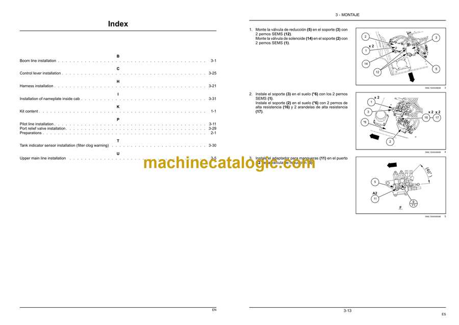
1 KIT CONTENT
Kit content . . . . . . . . . . . . . . . . . . . . . . . . . . . . . . . . . . . . . . . . . . . . . . . . . . . . . . . . . . . . . . . . . . . . . . . . . . . . . . . . . . 1-1
2 PRE-ASSEMBLY
PREPARING FOR ASSEMBLY
Preparations . . . . . . . . . . . . . . . . . . . . . . . . . . . . . . . . . . . . . . . . . . . . . . . . . . . . . . . . . . . . . . . . . . . . . . . . . . . . 2-1
3 ASSEMBLY
MULTI-PURPOSE CIRCUIT PROPORTIONAL CONTROL
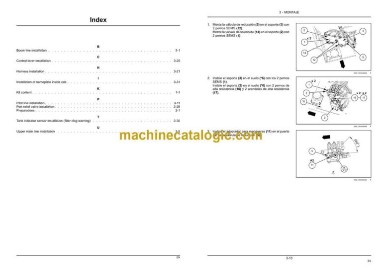
Boom line installation . . . . . . . . . . . . . . . . . . . . . . . . . . . . . . . . . . . . . . . . . . . . . . . . . . . . . . . . . . . . . . . 3-1
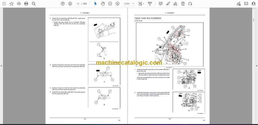
Upper main line installation. . . . . . . . . . . . . . . . . . . . . . . . . . . . . . . . . . . . . . . . . . . . . . . . . . . . . . . . . 3-5
Pilot line installation . . . . . . . . . . . . . . . . . . . . . . . . . . . . . . . . . . . . . . . . . . . . . . . . . . . . . . . . . . . . . . . 3-11
Harness installation. . . . . . . . . . . . . . . . . . . . . . . . . . . . . . . . . . . . . . . . . . . . . . . . . . . . . . . . . . . . . . . . 3-21
Control lever installation . . . . . . . . . . . . . . . . . . . . . . . . . . . . . . . . . . . . . . . . . . . . . . . . . . . . . . . . . . . 3-25
Port relief valve installation . . . . . . . . . . . . . . . . . . . . . . . . . . . . . . . . . . . . . . . . . . . . . . . . . . . . . . . . 3-29
Tank indicator sensor installation (filter clog warning) . . . . . . . . . . . . . . . . . . . . . . . . . . . . . 3-30
Installation of nameplate inside cab . . . . . . . . . . . . . . . . . . . . . . . . . . . . . . . . . . . . . . . . . . . . . . . 3-31


