Case E15X Mini Excavator Operators Manual (92730960, B280201081) (August 2025)
Out on small sites, driveways, tight backyards—this E15X mini excavator is the kind of machine that’s always squeezing between fences and working right up against buildings. This operators manual helps you run it the way it was designed, so you don’t fight the controls, overheat the hydraulics, or chew up tracks. Say you’re digging a trench along a sloped lawn: the book walks you through how the machine should feel, how to position the blade, and what to check if it starts to slide or the boom reacts slower under load.
Applications & Use Cases
- Trace and learn every control so you know how it’ll respond on slopes, in sticky clay, or when you swing with a full bucket.
- Follow the daily walk‑around to check fluids, inspect tracks and rollers, and verify pins and couplers before something loosens mid‑job.
- Use the startup and shutdown routines to bleed off hydraulic pressure, isolate electrical issues, and avoid yanking a pressurized hose.
- Align and route attachments the way Case expects, then test functions so you don’t bend a cylinder or rip a quick‑coupler.
- Troubleshoot odd behavior—like jerky travel or weak boom—by tracing simple checks before you call a tech.
FAQ
Q: Is this a PDF I can search on my phone or laptop?
A: Yes, it’s typically a searchable PDF, so you can jump to sections by keyword instead of scrolling forever.
Q: Can I print just a few sections to keep in the cab?
A: You usually can; most folks print the safety, controls, and maintenance schedules so they’re handy on the jobsite.
Safety Note
Always lower the attachment, set the blade, kill the engine, and relieve hydraulic pressure before you inspect or disconnect any hoses.
Case E15X Mini Excavator Index:
- 1 - INTRODUCTION
- 1.1 Regarding this manual
- 1.1.1 Manual consultation and terminology
- 1.2 Machine identification data
- 1.3 Manufacturer
- 1.3.1 Contact the after-sales network
- 1.4 Spare Parts
- 1.5 Information to the owner of the machine
- 1.6 Intended use
- 1.7 Prohibited use
- 2 - Safety
- 2.1 Safety symbol
- 2.2 General safety
- 2.2.1 Manual safety sign consultation
- 2.3 Safety signs and operation related labels
- 2.4 Machine driver
- 2.4.1 Personal Protective Equipment (PPE)
- 2.5 Work Area – Hazard Zone – No Entry Zone
- 2.6 List of Residual Risks
- 2.7 Safety procedures
- 2.8 Safety devices
- 2.8.1 Operator protective structure
- 2.8.1.1 FOPS Level I canopy (optional)
- 2.8.2 Seat belt
- 2.8.3 Controls cut-out lever
- 2.8.4 Slewing locking lever
- 2.8.5 Emergency stop button
- 3 - Technical data
- 3.1 General data
- 3.2 Engine
- 3.3 Power supply
- 3.4 Battery charge times
- 3.5 Electrical system
- 3.6 Hydraulic system
- 3.7 Performances
- 3.8 Digging arm
- 3.9 Dozer blade
- 3.10 Undercarriage
- 3.11 Fluid capacities
- 3.12 Brakes
- 3.13 Nominal lifting capacity
- 3.14 Rotary structure
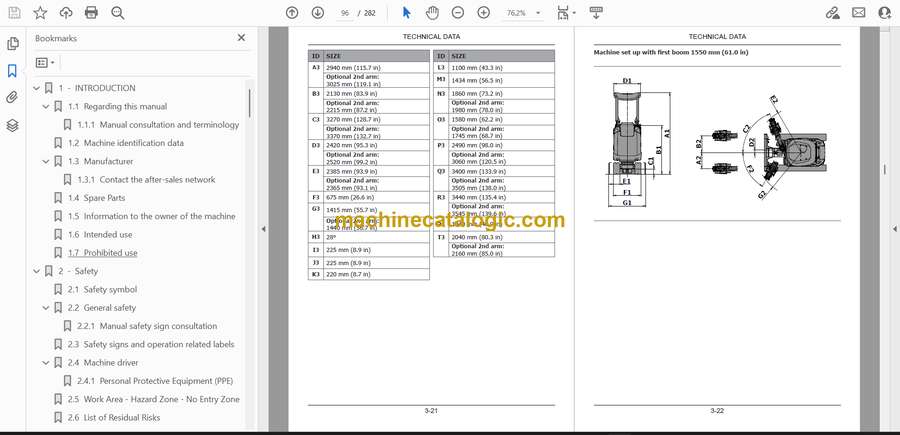
- 3.15 Overall dimensions
- 4 - Transporting the machine
- 4.1 Shipping dimensions
- 4.2 Loading/unloading operations
- 4.3 Securing the machine on the means of transport
- 4.4 Lifting of the machine
- 4.5 Recovering and pulling the machine
- 5 - Controls and tools
- 5.1 Description of main controls and levers
- 5.2 Description of left control console
- 5.3 Description of right control console
- 5.4 Roller operation
- 5.5 Optional electrical buttons on the joystick
- 5.6 Auxiliary power socket on console
- 5.7 Machine status warning indicators
- 5.8 Control panel
- 5.9 Display
- 5.10 Battery disconnect switch (emergency stop button)
- 5.11 Geo-localisation system (optional)
- 6 - Using the machine
- 6.1 Commissioning
- 6.2 Battery disconnect switch (emergency stop button)
- 6.3 Driver’s seat
- 6.4 Arm rests
- 6.5 Seat belt
- 6.6 Controls cut-out lever
- 6.7 Slewing locking lever
- 6.8 Auxiliary electrical socket for the rotating head lamp
- 6.9 Control panel operation
- 6.10 HOME page
- 6.10.1 Time
- 6.10.2 Machine hours
- 6.10.3 Control mode
- 6.10.4 Engine data and battery data
- 6.10.5 Pop-up messages (information/alarms)
- 6.10.6 Warning indicators
- 6.10.7 Menu button
- 6.10.8 Working lights indicator lights
- 6.10.9 Dozer blade mode/undercarriage width indicator light
- 6.10.10 Work mode management
- 6.11 MENU screen
- 6.11.1 BATTERY screen
- 6.11.2 ENGINE screen
- 6.11.3 EQUIPMENT screen
- 6.11.3.1 Equipment SETTINGS sub-menu
- 6.11.4 TEMPERATURES screen
- 6.11.5 SOFTWARE screen
- 6.11.6 SERVICE screen
- 6.11.7 SETTINGS screen
- 6.11.7.1 CONTROL START MODE
- 6.11.7.2 PRESSURE RELIEF
- 6.11.7.3 PARTIAL HOURS RESET
- 6.11.7.4 LANGUAGE sub-menu
- 6.11.7.5 DATE/TIME sub-menu
- 6.11.7.6 COMMAND CONFIGURATION
- 6.11.7.7 UNIT OF MEASURE
- 6.11.7.8 DISPLAY BRIGHTNESS
- 6.11.8 LIFETIME DATA COUNTER Screen
- 6.11.9 CONTROL MODE screen
- 6.11.9.1 INDIVIDUAL sub-menu
- 6.12 Visibility
- 6.13 Starting the machine
- 6.13.1 Checks prior to the start up
- 6.13.2 Procedure for starting the machine
- 6.14 Battery power
- 6.15 Machine charging mode
- 6.15.1 On-board battery charger
- 6.15.2 Portable battery charger (optional)
- 6.16 Electrical isolation
- 6.17 Horn
- 6.18 Work lights
- 6.19 Operating at low temperatures
- 6.20 Precautions during operation
- 6.21 Stopping and parking the machine
- 6.22 Machine movement
- 6.22.1 Forward and reverse travel
- 6.22.2 Pivoting the machine around its axis
- 6.22.3 Turning while moving forward
- 6.22.4 Turning while reversing
- 6.22.5 Precautions during the operation of the tracks
- 6.23 Travel speed
- 6.24 Dozer blade control/undercarriage width adjustment lever
- 6.24.1 Dozer blade control
- 6.24.2 Undercarriage width adjustment control
- 6.25 Extendible dozer blade with extensions
- 6.26 Operating the boom
- 6.26.1 Left Joystick
- 6.26.2 Right joystick
- 6.26.3 ISO-SAE controls layout TPSS function
- 6.27 Boom swing control
- 6.28 Discharge residual pressure in the hydraulic system
- 6.29 Boom swing/AUX2 hydraulics system selector button (optional)
- 6.30 Auxiliary hydraulic systems
- 6.30.1 Connection of equipment to the hydraulic systems
- 6.30.2 Connections on second boom
- 6.30.3 AUX1 Auxiliary hydraulic system
- 6.30.3.1 AUX1 hydraulic system three-way switch
- 6.30.3.2 Single-acting mode AUX1
- 6.30.3.3 Double-acting mode AUX1
- 6.30.4 AUX2 Auxiliary hydraulic system (optional)
- 6.31 Emergency lifting-boom lowering procedure
- 6.32 Protective structure opening procedure
- 6.32.1 Precautions to be taken during transport
- 6.32.2 Precautions to be taken when travelling in low-height spaces
- 6.32.3 Procedure
- 6.33 Daily storage
- 7 - Recommended optional equipment
- 7.1 Safety precautions
- 7.1.1 Specifications on authorised equipment
- 7.2 Equipment with standard coupling (pins)
- 7.2.1 Installation and removal
- 7.3 Quick-coupling
- 7.4 Demolition hammer
- 7.4.1 Installation and removal
- 7.4.2 Precautions for use
- 7.4.3 Operation
- 8 - Maintenance
- 8.1 Safety
- 8.1.1 Placement out of service for maintenance
- 8.2 Tools and equipment for maintenance
- 8.3 Guards
- 8.3.1 Central compartment hood
- 8.3.2 High voltage compartment guard
- 8.3.3 Rear compartment cover
- 8.3.4 Hydraulic oil tank compartment guard
- 8.3.5 Document glove box guard
- 8.4 Electrical system
- 8.5 Tracks
- 8.6 Refilling
- 8.6.1 Refilling quantity table
- 8.6.2 Products for lubrication
- 8.6.3 Hydraulic system oil
- 8.6.3.1 Requirements for using ecological hydraulic oil
- 8.6.3.2 Scheduled plan for analysis and control of eco-friendly hydraulic oil
- 8.6.3.3 Requirements for the sampling of eco-friendly hydraulic oil
- 8.7 Tightening torque tables
- 8.8 Periodic maintenance
- 8.8.1 Performance check
- 8.8.2 Cleaning of radiator and heat sink
- 8.8.3 Check the hydraulic oil level
- 8.8.4 Change discharge circuit hydraulic oil filter
- 8.8.5 Hydraulic system oil sampling/replacement
- 8.8.6 Replacement of intake circuit hydraulic oil filter
- 8.8.7 Check the condition of hydraulic lines
- 8.8.8 Full charge of the battery
- 8.8.9 Check that the screws of the drive wheel/rollers are tight
- 8.8.10 Track service position
- 8.8.11 Track tension check
- 8.8.12 Adjusting the track tension
- 8.8.13 Translation motors and rotation gear motor
- 8.8.14 Lubrication of pins
- 8.8.15 Electrical test
- 8.9 Long inactivity periods
- 8.10 Long-term storage
- 9 - Electrical parts
- 9.1 Fuses and relays
- 9.2 Work lights replacement
- 9.3 LED strip replacement
- 9.4 Auxiliary battery
- 10 - RESCUE SHEET
CNH


