$ 0
0
$ 0
0

Case TL100 Mini Track Loader Operator’s Manual (92846249)

Format: PDF (Printable Document)

File Language: English

File Pages: 262

File Size: 27.14 MB (Speed Download Link)

Brand: Case

Model: TL100

Equipment: Mini Track Loader

Book No: 92846249

Date: October 2025

Type of Document: Operator’s Manual

Categories: ,

$ 45

Share:

Case TL100 Mini Track Loader Operator’s Manual (92846249)

The TL100 is a small tracked loader, good for tight sites, backfilling, grading around houses, and loading trucks where a skid steer spins too much. People grab this operator's manual when the machine shows up with no book, when they want the right daily checks and grease points, or when they need to know what fluids and intervals Case actually calls for. If you're trying to keep operators from abusing a machine and avoid stupid downtime, this is the book they keep in the cab.

What this manual helps you do

  • Operate the TL100 safely, with the right start-up, shutdown, and travel procedures
  • Set up the controls, safety locks, and basic machine settings the way Case intended
  • Check daily items like engine oil, coolant, hydraulic level, and track condition before a shift
  • Service regular items on schedule, like filters and fluid changes, using the correct types of fluids
  • Grease all the fittings and inspect wear points so you don't lose time to avoidable failures

Who this is for

This is for an owner-operator, excavation contractor, rental yard, or fleet manager who wants correct operation, daily maintenance, and safety info for a Case TL100 mini track loader. If you need step-by-step repair, teardown, or wiring diagnostics, you want the service manual or an electrical manual instead, not this operator's manual.

FAQ

Q: Is this a searchable PDF and can I read wiring diagrams in it?

A: It should be a searchable PDF, and any basic schematics are usually clear enough to zoom on a laptop or tablet, but it is not a full wiring manual.

Q: Will this cover my TL100 no matter the year?

A: It is for TL100 mini track loaders that match the manual's ID; if your serial plate says TL100 and the manual number 92846249 matches the listing, you're in the right zone.

Q: I just bought a rough used TL100. Is this the right book to get it back in shape?

A: It's the right book to run and maintain it correctly. For fixing existing problems, you'll still want the service manual.

Bottom line: If you need controls, safety, fluids, and maintenance for a Case TL100 mini track loader, this is the right manual. If you're chasing repairs, it's not.

📘 Show Index

Table of Contents:

  • 1 - Introduction
    • 1.1 – Regarding this manual
      • 1.1.1 – Manual consultation and terminology
    • 1.2 – Machine identification data
    • 1.3 – Manufacturer
      • 1.3.1 – Contact the manufacturer
      • 1.3.2 – Spare Parts
    • 1.4 – Information to the owner of the machine
    • 1.5 – Intended use
    • 1.6 – Prohibited use
    • 1.7 – Emissions overview
  • 2 - Safety
    • 2.1 – Safety symbol
    • 2.2 – General safety
      • 2.2.1 – Manual safety sign consultation
    • 2.3 – Safety signs and operation related labels
    • 2.4 – Machine driver
      • 2.4.1 – Personal Protective Equipment (PPE)
    • 2.5 – Work Area – Hazard Zone – No Entry Zone
    • 2.6 – List of Residual Risks
    • 2.7 – Safety procedures
    • 2.8 – Safety devices
      • 2.8.1 – Control cut-out button
      • 2.8.2 – Parking brake button
  • 3 - Technical data
    • 3.1 – General data
    • 3.2 – Engine
    • 3.3 – Hydraulic system
    • 3.4 – Performance
    • 3.5 – Counterweight
    • 3.6 – Undercarriage
    • 3.7 – Fluid capacities
    • 3.8 – Electrical system
    • 3.9 – Brakes
    • 3.10 – Operating load
      • 3.10.1 – Bucket
      • 3.10.2 – Pallet forks
    • 3.11 – Overall dimensions
  • 4 - Transporting the machine
    • 4.1 – Transportation dimensions
    • 4.2 – Loading/unloading operations
    • 4.3 – Securing the machine on the mean of transport
    • 4.4 – Lifting the machine
      • 4.4.1 – Lifting procedure
    • 4.5 – Recovering and pulling the machine
  • 5 - Controls and instrumentation
    • 5.1 – Description of controls
    • 5.2 – Description of control levers
    • 5.3 – Description of dashboard
    • 5.4 – Roller operation
    • 5.5 – Auxiliary power socket on console
    • 5.6 – Control panel
    • 5.7 – Battery isolator switch
    • 5.8 – Geo-localisation system
  • 6 - Using the machine
    • 6.1 – Commissioning
    • 6.2 – Battery isolator switch
    • 6.3 – Driver seat
    • 6.4 – Control cut-out button
    • 6.5 – Parking brake button
    • 6.6 – Visibility
      • 6.6.1 – Travel position
    • 6.7 – Starting the engine
      • 6.7.1 – Inspections prior to starting
      • 6.7.2 – Procedure for starting the machine
    • 6.8 – Engine jump-starting procedure
      • 6.8.1 – Connecting the additional cables
      • 6.8.2 – Starting the engine
      • 6.8.3 – Removing the additional cables
    • 6.9 – Horn
    • 6.10 – Work lights
    • 6.11 – Operation at low temperatures or during winter
    • 6.12 – Precautions during operation
    • 6.13 – Stopping and parking the machine
    • 6.14 – Refuelling
    • 6.15 – Throttle lever
    • 6.16 – Machine movement
      • 6.16.1 – Left Joystick
      • 6.16.2 – Forward and reverse travel
      • 6.16.3 – Turning while moving forward
      • 6.16.4 – Rotation while reversing
        • 6.16.4.1 – Precautions during the operation of the tracks
    • 6.17 – Operating the boom
      • 6.17.1 – Right joystick
      • 6.17.2 – Boom floating control
    • 6.18 – Using the bucket
    • 6.19 – Discharge residual pressure in the hydraulic system
    • 6.20 – Auxiliary hydraulic systems
      • 6.20.1 – Connection of equipment to the hydraulic systems
      • 6.20.2 – AUX1 Auxiliary hydraulic system
        • 6.20.2.1 – AUX1 hydraulic system three-way switch
        • 6.20.2.2 – Single-acting mode AUX1
        • 6.20.2.3 – Double-acting mode AUX1
        • 6.20.2.4 – Auxiliary hydraulic system AUX1 latch with operator not in the driver's seat
      • 6.20.3 – Drain line (direct to tank – optional)
    • 6.21 – Electrical auxiliary systems (optional)
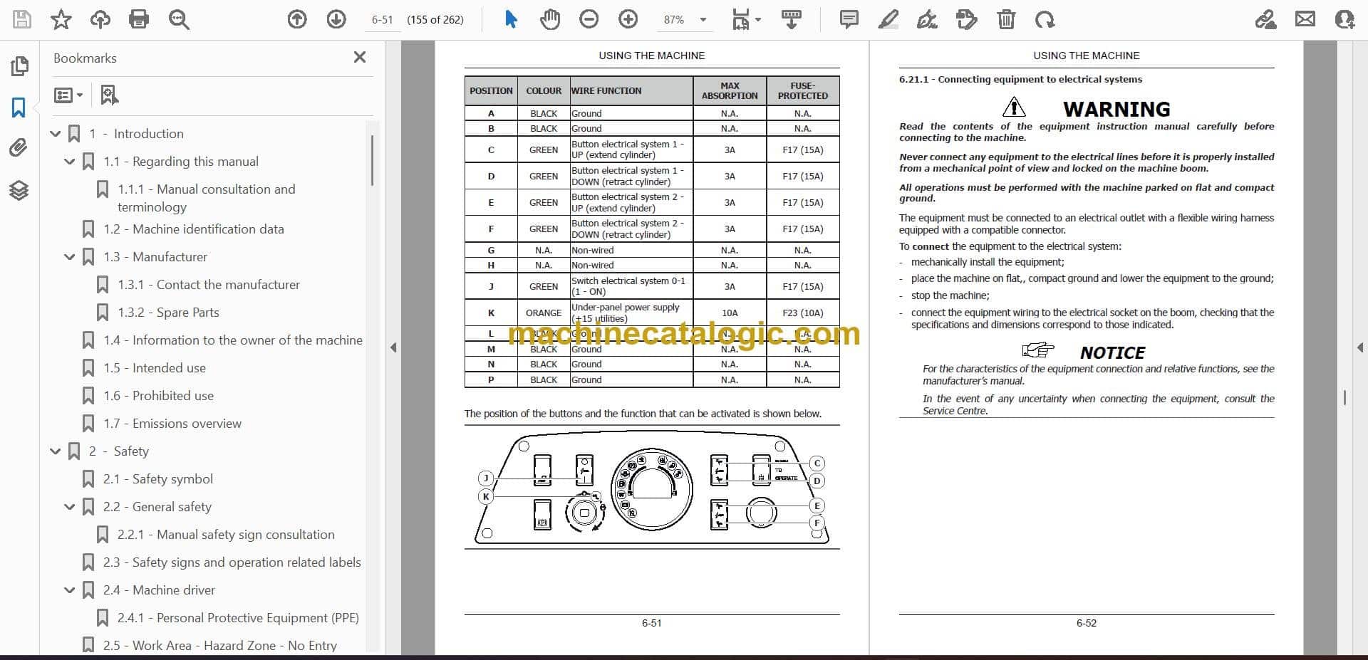
      • 6.21.1 – Connecting equipment to electrical systems
      • 6.21.2 – Operation of electrical auxiliary systems
    • 6.22 – Emergency boom lowering procedure
    • 6.23 – Procedure for the temporary activation of the controls with the operator not detected in the driver's seat
    • 6.24 – Supplementary counterweight installation and removal procedure
    • 6.25 – Daily storage
  • 7 - Recommended optional equipment
    • 7.1 – Safety precautions
    • 7.2 – Specifications on authorised equipment
    • 7.3 – Operating capacity
    • 7.4 – Quick-coupling
    • 7.5 – Precautions
  • 8 - Maintenance
    • 8.1 – Safety
      • 8.1.1 – Putting the machine out of service for maintenance
    • 8.2 – Tools and equipment for maintenance
    • 8.3 – Safety devices
      • 8.3.1 – Engine hood
      • 8.3.2 – Electrical components guard
      • 8.3.3 – Upper compartment cover (cushion)
      • 8.3.4 – Lower compartment cover
      • 8.3.5 – Oil tank compartment guard
    • 8.4 – Locking the boom for maintenance
    • 8.5 – Electrical system
    • 8.6 – Tracks
    • 8.7 – Refilling
      • 8.7.1 – Refilling quantity table
      • 8.7.2 – Products for lubrication
      • 8.7.3 – Fuel
      • 8.7.4 – Engine oil
      • 8.7.5 – Cooling liquid
      • 8.7.6 – Hydraulic system oils
        • 8.7.6.1 – Requirements for using eco-friendly hydraulic oil
        • 8.7.6.2 – Scheduled plan for analysis and control of ecological hydraulic oil
        • 8.7.6.3 – Requirements for the sampling of eco-friendly hydraulic oil
    • 8.8 – Battery
      • 8.8.1 – Fitting and removing the battery
      • 8.8.2 – Recharging the battery
    • 8.9 – Tightening torque tables
    • 8.10 – Weights of the material in a pile
    • 8.11 – Regular maintenance
      • 8.11.1 – Performance check
      • 8.11.2 – Check of engine oil level
      • 8.11.3 – Replacement of engine oil
      • 8.11.4 – Replacement of engine oil filter
      • 8.11.5 – Check of cooling liquid level
      • 8.11.6 – Replacement of cooling liquid
      • 8.11.7 – Check and replacement of cooling liquid sleeves
      • 8.11.8 – Cleaning the radiator
      • 8.11.9 – Check of hydraulic oil level
      • 8.11.10 – Change discharge circuit hydraulic oil filter
      • 8.11.11 – Hydraulic system oil sampling/replacement
      • 8.11.12 – Replacement of intake circuit hydraulic oil filter
      • 8.11.13 – Check of hydraulic line condition
      • 8.11.14 – Checking that the screws of the undercarriage are tight
      • 8.11.15 – Check of track tension
      • 8.11.16 – Adjusting the track tension
      • 8.11.17 – Checking tension and replacing alternator belt
      • 8.11.18 – Checking tension and replacing fan belt
      • 8.11.19 – Check and replacement of air filter
      • 8.11.20 – Replacement of fuel filter
      • 8.11.21 – Draining the fuel tank
      • 8.11.22 – Draining fuel circuit water and replacing water separator filter
      • 8.11.23 – Cleaning the filter on the fuel intake
      • 8.11.24 – Bleeding air from the fuel circuit
      • 8.11.25 – Replacement of travel engine oil
    • 8.12 – Lubrication of pins
    • 8.13 – Long inactivity periods
    • 8.14 – Dismantling the machine
  • 9 - electrical components
    • 9.1 – Fuses and relays
      • 9.1.1 – Control box fuses
      • 9.1.2 – Control unit relays
      • 9.1.3 – Engine fuses and relays
    • 9.2 – Work lights replacement
    • 9.3 – LED strip replacement

CNH Manuals & Software

Related Manuals

0
    0
    Your Cart
    Your cart is emptyReturn to Shop