Format: PDF (Printable Document)
File Language: English
File Pages: 458
File Size: 42.82 MB (Speed Download Link)
Brand: Case
Model: True-Tandem 375 22–37 Foot Disk Harrow
Part No: 91710729
Date: July 2021
Type of Document: Assembly Instructions
$ 45
1 SAFETY INFORMATION
Personal safety . . . . . . . . . . . . . . . . . . . . . . . . . . . . . . . . . . . . . . . . . . . . . . . . . . . . . . . . . . . . . . . . . . . . . . . . . . . . . 1-1
General information and safety. . . . . . . . . . . . . . . . . . . . . . . . . . . . . . . . . . . . . . . . . . . . . . . . . . . . . . . . . . . . . 1-2
2 GENERAL INFORMATION
Product overview . . . . . . . . . . . . . . . . . . . . . . . . . . . . . . . . . . . . . . . . . . . . . . . . . . . . . . . . . . . . . . . . . . . . . . . . . . . 2-1
Torque . . . . . . . . . . . . . . . . . . . . . . . . . . . . . . . . . . . . . . . . . . . . . . . . . . . . . . . . . . . . . . . . . . . . . . . . . . . . . . . . . . . . . . 2-4
Special bolt torque. . . . . . . . . . . . . . . . . . . . . . . . . . . . . . . . . . . . . . . . . . . . . . . . . . . . . . . . . . . . . . . . . . . . . . . . . . 2-9
Torque – Standard torque data for hydraulic connections . . . . . . . . . . . . . . . . . . . . . . . . . . . . . . . . . 2-10
Soil preparation/Finishing – Basic instructions. . . . . . . . . . . . . . . . . . . . . . . . . . . . . . . . . . . . . . . . . . . . . 2-17
Attaching the implement to the tractor. . . . . . . . . . . . . . . . . . . . . . . . . . . . . . . . . . . . . . . . . . . . . . . . . . . . . 2-18
Hydraulic hose connections – Standard frame control. . . . . . . . . . . . . . . . . . . . . . . . . . . . . . . . . . . . . 2-24
Hydraulic hose connections – Electronic frame control . . . . . . . . . . . . . . . . . . . . . . . . . . . . . . . . . . . . 2-26
3 PRE-ASSEMBLY
PREPARING FOR ASSEMBLY
Required building and equipment . . . . . . . . . . . . . . . . . . . . . . . . . . . . . . . . . . . . . . . . . . . . . . . . . . . . . . 3-1
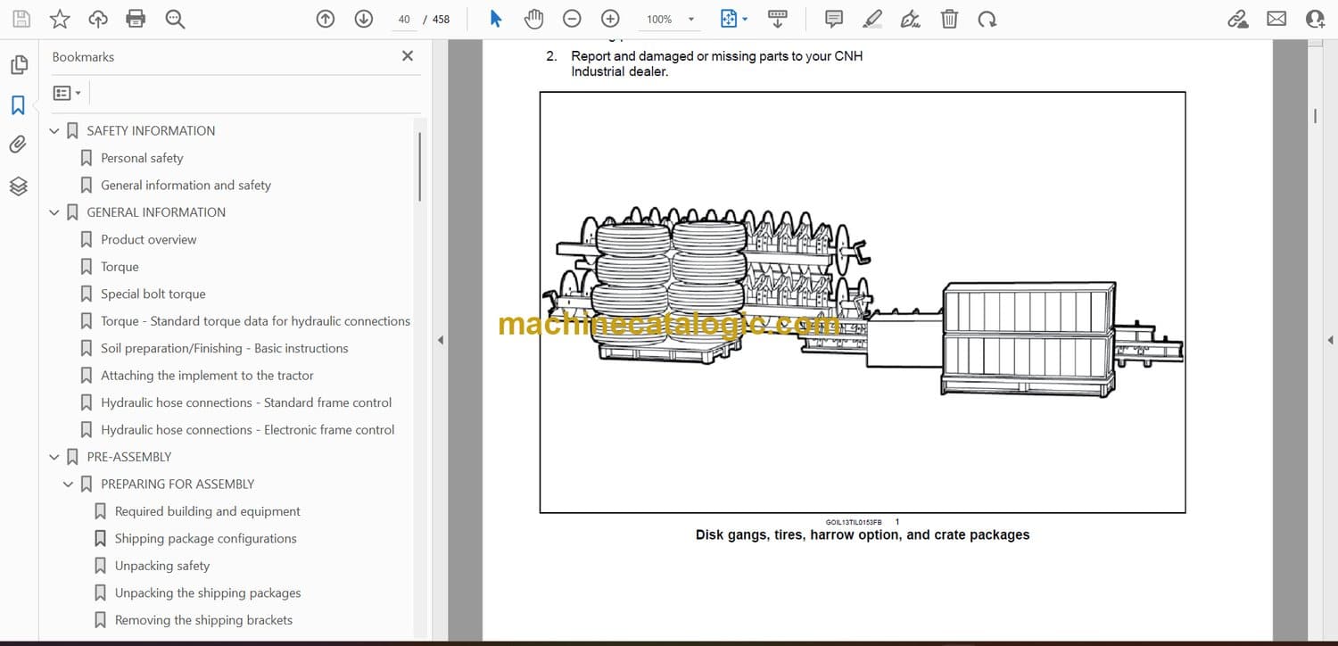
Shipping package configurations . . . . . . . . . . . . . . . . . . . . . . . . . . . . . . . . . . . . . . . . . . . . . . . . . . . . . . . 3-2
Unpacking safety . . . . . . . . . . . . . . . . . . . . . . . . . . . . . . . . . . . . . . . . . . . . . . . . . . . . . . . . . . . . . . . . . . . . . . . 3-4
Unpacking the shipping packages. . . . . . . . . . . . . . . . . . . . . . . . . . . . . . . . . . . . . . . . . . . . . . . . . . . . . . 3-6
Removing the shipping brackets . . . . . . . . . . . . . . . . . . . . . . . . . . . . . . . . . . . . . . . . . . . . . . . . . . . . . . . 3-7
Unpacking one-piece main frame and pull frame . . . . . . . . . . . . . . . . . . . . . . . . . . . . . . . . . . . . . . 3-8
4 ASSEMBLY
ASSEMBLY
Before assembly. . . . . . . . . . . . . . . . . . . . . . . . . . . . . . . . . . . . . . . . . . . . . . . . . . . . . . . . . . . . . . . . . . . . 4-1
Main frame assembly. . . . . . . . . . . . . . . . . . . . . . . . . . . . . . . . . . . . . . . . . . . . . . . . . . . . . . . . . . . . . . . 4-2
Universal Control Module (UCM) installation – Electronic frame control . . . . . . . . . . . 4-3
Main lift valve block assembly to main frame – Electronic frame control . . . . . . . . . . . 4-9
Tandem stop installation – 7.6 m (22 ft) and 8.5 m (25 ft) implements with 26″ disk blade
option . . . . . . . . . . . . . . . . . . . . . . . . . . . . . . . . . . . . . . . . . . . . . . . . . . . . . . . . . . . . . . . . . . . . . . . . . . . . . . 4-16
Transport hub and spindle installation. . . . . . . . . . . . . . . . . . . . . . . . . . . . . . . . . . . . . . . . . . . . . 4-17
Main frame lift cylinder installation – Standard frame control . . . . . . . . . . . . . . . . . . . . . . 4-19
Main frame lift cylinder installation – Electronic frame control . . . . . . . . . . . . . . . . . . . . . 4-23
Center shank assembly . . . . . . . . . . . . . . . . . . . . . . . . . . . . . . . . . . . . . . . . . . . . . . . . . . . . . . . . . . . 4-27
Decal installation . . . . . . . . . . . . . . . . . . . . . . . . . . . . . . . . . . . . . . . . . . . . . . . . . . . . . . . . . . . . . . . . . . 4-31
Small and medium main frame disk gang installation . . . . . . . . . . . . . . . . . . . . . . . . . . . . . 4-33
Large main frame disk gang installation. . . . . . . . . . . . . . . . . . . . . . . . . . . . . . . . . . . . . . . . . . . 4-36
229 mm (9 in) cushion main frame disk gang identification . . . . . . . . . . . . . . . . . . . . . . . 4-41
229 mm (9 in) rigid main frame disk blade identification . . . . . . . . . . . . . . . . . . . . . . . . . . 4-47
Wing frame to main frame assembly . . . . . . . . . . . . . . . . . . . . . . . . . . . . . . . . . . . . . . . . . . . . . . 4-53
229 mm (9 in) cushion wing frame disk gang identification . . . . . . . . . . . . . . . . . . . . . . . 4-55
229 mm (9 in) rigid wing frame disk gang identification . . . . . . . . . . . . . . . . . . . . . . . . . . . 4-71
Wheel pedestals to wing frame assembly . . . . . . . . . . . . . . . . . . . . . . . . . . . . . . . . . . . . . . . . . 4-87
Wing frame eye bolt installation . . . . . . . . . . . . . . . . . . . . . . . . . . . . . . . . . . . . . . . . . . . . . . . . . . . 4-90
Wing frame lift cylinder installation – Standard frame control. . . . . . . . . . . . . . . . . . . . . . 4-92
Wing frame lift cylinder installation – Electronic frame control . . . . . . . . . . . . . . . . . . . . . 4-96
Wing stop installation for 6.7 – 9.4 m (22 – 31 ft) implements . . . . . . . . . . . . . . . . . . . 4-100
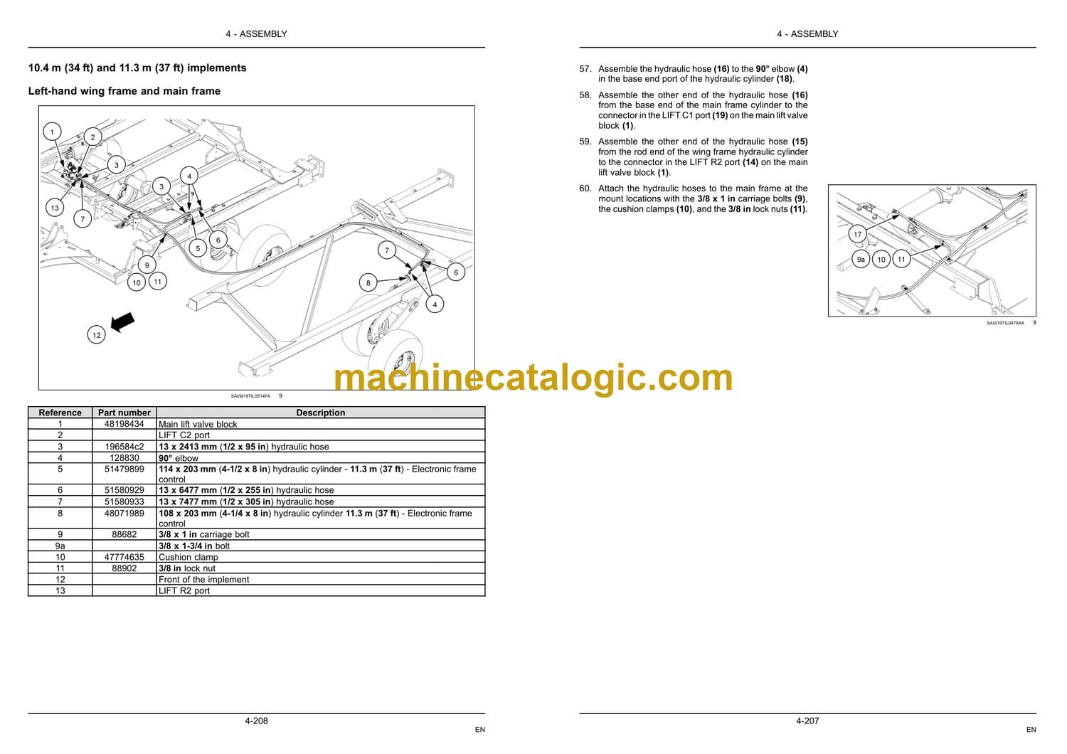
Wing stop installation for 10.4 m (34 ft) and 11.3 m (37 ft) implements . . . . . . . . . . 4-104
Spring leveling link assembly installation. . . . . . . . . . . . . . . . . . . . . . . . . . . . . . . . . . . . . . . . . 4-107
Single Point Depth Control (SPDC) assembly . . . . . . . . . . . . . . . . . . . . . . . . . . . . . . . . . . . 4-110
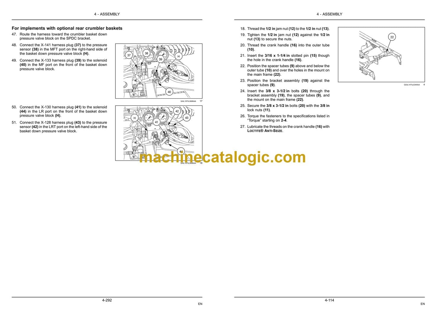
Single basket down pressure valve block installation – Electronic frame control . 4-115
Pull frame to main frame assembly. . . . . . . . . . . . . . . . . . . . . . . . . . . . . . . . . . . . . . . . . . . . . . . 4-118
Jack installation. . . . . . . . . . . . . . . . . . . . . . . . . . . . . . . . . . . . . . . . . . . . . . . . . . . . . . . . . . . . . . . . . . . 4-120
Swinging hose boom to pull frame assembly. . . . . . . . . . . . . . . . . . . . . . . . . . . . . . . . . . . . . 4-121
Auxiliary valve block installation to pull frame – Electronic frame control. . . . . . . . . 4-123
Pull frame leveling – turnbuckle assembly . . . . . . . . . . . . . . . . . . . . . . . . . . . . . . . . . . . . . . . . 4-129
Fore/aft cylinder hydraulic fitting and hose assembly – Standard frame control. . 4-131
Fore/aft cylinder hydraulic fitting and hose assembly – Electronic frame control . 4-142
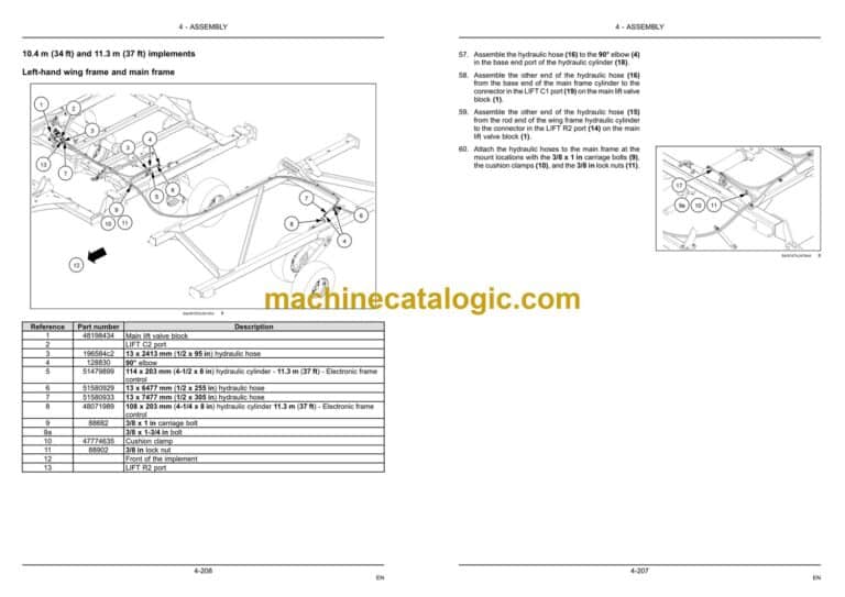
Main frame and wing frame lift hydraulic hose installation – Standard frame control4-148
Main frame and wing frame lift hydraulic hose installation – Electronic frame control
. . . . . . . . . . . . . . . . . . . . . . . . . . . . . . . . . . . . . . . . . . . . . . . . . . . . . . . . . . . . . . . . . . . . . . . . . . . . . . . . 4-196
Hydraulic hose support bracket installation . . . . . . . . . . . . . . . . . . . . . . . . . . . . . . . . . . . . . . 4-214
Single Point Depth Control (SPDC) hydraulic hose installation – Electronic frame control
. . . . . . . . . . . . . . . . . . . . . . . . . . . . . . . . . . . . . . . . . . . . . . . . . . . . . . . . . . . . . . . . . . . . . . . . . . . . . . . . 4-217
Main lift valve block to auxiliary valve block hydraulic hose connections – Electronic
frame control . . . . . . . . . . . . . . . . . . . . . . . . . . . . . . . . . . . . . . . . . . . . . . . . . . . . . . . . . . . . . . . . . . . . . 4-223
Auxiliary valve block to tractor hydraulic hose connections – Electronic frame control
. . . . . . . . . . . . . . . . . . . . . . . . . . . . . . . . . . . . . . . . . . . . . . . . . . . . . . . . . . . . . . . . . . . . . . . . . . . . . . . . 4-227
Wing fold hydraulics . . . . . . . . . . . . . . . . . . . . . . . . . . . . . . . . . . . . . . . . . . . . . . . . . . . . . . . . . . . . . . 4-231
Hydraulic hose identification tags – Standard frame control . . . . . . . . . . . . . . . . . . . . . . 4-252
Hydraulic hose identification tags – Electronic frame control . . . . . . . . . . . . . . . . . . . . . 4-254
Warning light and tail light installation . . . . . . . . . . . . . . . . . . . . . . . . . . . . . . . . . . . . . . . . . . . . 4-256
Red tail/stop light bracket assembly. . . . . . . . . . . . . . . . . . . . . . . . . . . . . . . . . . . . . . . . . . . . . . 4-260
Amber hazard light bracket assembly . . . . . . . . . . . . . . . . . . . . . . . . . . . . . . . . . . . . . . . . . . . . 4-262
Slow-Moving Vehicle (SMV) bracket and sign assembly . . . . . . . . . . . . . . . . . . . . . . . . . 4-264
Safety lighting installation . . . . . . . . . . . . . . . . . . . . . . . . . . . . . . . . . . . . . . . . . . . . . . . . . . . . . . . . 4-266
6.7 m (22 ft) and 7.6 m (25 ft) implements . . . . . . . . . . . . . . . . . . . . . . . . . . . 4-266
8.5 m (28 ft) and 9.4 m (31 ft) implements . . . . . . . . . . . . . . . . . . . . . . . . . . . 4-270
10.4 m (34 ft) and 11.3 m (37 ft) implements . . . . . . . . . . . . . . . . . . . . . . . . 4-275
Wiring harness installation – Electronic frame control . . . . . . . . . . . . . . . . . . . . . . . . . . . . 4-284
Wiring harness cable tie installation . . . . . . . . . . . . . . . . . . . . . . . . . . . . . . . . . . . . . . . . . . . . . . 4-294
Pivoting stabilizer wheel assembly . . . . . . . . . . . . . . . . . . . . . . . . . . . . . . . . . . . . . . . . . . . . . . . 4-296
Rear attachment mounting tube . . . . . . . . . . . . . . . . . . . . . . . . . . . . . . . . . . . . . . . . . . . . . . . . . . 4-301
Installation for 6.7 m (22 ft) and 7.6 m (25 ft) implements . . . . . . . . . . . 4-301
Installation for 8.5 m (28 ft) and 9.4 m (31 ft) implements . . . . . . . . . . . 4-305
Installation for 10.4 m (34 ft) and 11.3 m (37 ft) implements. . . . . . . . . 4-309
Basket arm and cylinder installation. . . . . . . . . . . . . . . . . . . . . . . . . . . . . . . . . . . . . . . . . . . . . . 4-313
Arm to rear attachment mounting tube layouts . . . . . . . . . . . . . . . . . . . . . . . . . . . . . . . . . . . 4-316
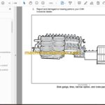
6.7 (22 ft) and 7.6 m (25 ft) single basket leveler hydraulic routing – Electronic frame
control . . . . . . . . . . . . . . . . . . . . . . . . . . . . . . . . . . . . . . . . . . . . . . . . . . . . . . . . . . . . . . . . . . . . . . . . . . . . 4-322
8.5 (28 ft) and 9.4 m (31 ft) single basket leveler hydraulic routing – Electronic frame
control . . . . . . . . . . . . . . . . . . . . . . . . . . . . . . . . . . . . . . . . . . . . . . . . . . . . . . . . . . . . . . . . . . . . . . . . . . . . 4-335
10.4 m (34 ft) and 11.3 m (37 ft) single basket leveler hydraulic routing – Electronic
frame control . . . . . . . . . . . . . . . . . . . . . . . . . . . . . . . . . . . . . . . . . . . . . . . . . . . . . . . . . . . . . . . . . . . . . 4-348
Decal installation . . . . . . . . . . . . . . . . . . . . . . . . . . . . . . . . . . . . . . . . . . . . . . . . . . . . . . . . . . . . . . . . . 4-362
Single basket to arm assembly . . . . . . . . . . . . . . . . . . . . . . . . . . . . . . . . . . . . . . . . . . . . . . . . . . . 4-364
6.7 m (22 ft) single basket size and location . . . . . . . . . . . . . . . . . . . . . . . . . 4-366
7.6 m (25 ft) single basket size and location . . . . . . . . . . . . . . . . . . . . . . . . . 4-367
8.5 m (28 ft) single basket size and location . . . . . . . . . . . . . . . . . . . . . . . . . 4-368
9.4 m (31 ft) single basket size and location . . . . . . . . . . . . . . . . . . . . . . . . . 4-369
10.4 m (34 ft) single basket size and location. . . . . . . . . . . . . . . . . . . . . . . . 4-370
11.3 m (37 ft) single basket size and location . . . . . . . . . . . . . . . . . . . . . . . . 4-371
Optional rear jack stand . . . . . . . . . . . . . . . . . . . . . . . . . . . . . . . . . . . . . . . . . . . . . . . . . . . . . . . . . . 4-372
Hydraulic schematic – Electronic frame control. . . . . . . . . . . . . . . . . . . . . . . . . . . . . . . . . . . 4-374
5 POST-ASSEMBLY
INSTRUCTIONS
Removing air from the hydraulic system – Standard frame control . . . . . . . . . . . . . . . . . . . . . 5-1
Initial load of software to Universal Control Module (UCM) with Electronic Service Tool
(EST) – Electronic frame control . . . . . . . . . . . . . . . . . . . . . . . . . . . . . . . . . . . . . . . . . . . . . . . . . . . . . . . . 5-4
Removing air from the hydraulic system – Electronic frame control . . . . . . . . . . . . . . . . . . . 5-21
Single Point Depth Control (SPDC) adjustment . . . . . . . . . . . . . . . . . . . . . . . . . . . . . . . . . . . . . . . 5-23
Initial implement set-up . . . . . . . . . . . . . . . . . . . . . . . . . . . . . . . . . . . . . . . . . . . . . . . . . . . . . . . . . . . . . . . . 5-24
FINAL-CHECK
Assembly checklist . . . . . . . . . . . . . . . . . . . . . . . . . . . . . . . . . . . . . . . . . . . . . . . . . . . . . . . . . . . . . . . . . . . . 5-25

