Format: PDF (Printable Document)
File Language: English
File Pages: 1373
File Size: 87.60 MB (Speed Download Link)
Brand: Clark
Model: C60d, C70d, C80d, C80D900, C60L, C70L, C75L Forklift
Book No: SM1023
Part No: 8126735
Type of Document: Service Manual
$ 40
CONTENTS
GROUP SA SAFE MAINTENANCE
Section 1 Safety
Section 2 Lifting, Jacking, and Blocking the Truck
Section 3 Towing
GROUP PS PERIODIC SERVICE
Section 1 Maintenance Schedules
Section 2 The Planned Maintenance Program
GROUP 00 (D-IVECO) DIESEL ENGINE (Tier 3)
Section 1 GENERAL SPECIFICATIONS
Section 2 Fuel
Section 3 DUTY – INDUSTRIAL APPLICATION
Section 4 OVERHAUL AND TECHNICAL SPECIFICATIONS
Section 5 TOOLS
Section 6 Engine Replacement
GROUP 00 (D-DEUTZ) ENGINE (DEUTZ – Tier 4)
Section 1 General
Section 2 Servicing and Maintenance Work
Section 3 Removing and Installing
Section 4 Special Tools
GROUP 00(L) ENGINE (GM V6 4.3L)
Section 1 ENGINE REMOVAL AND REPLACEMENT
Section 2 4.3 LITER V6 ENGINE REPAIR PROCEDURES
Section 3 COOLING SYSTEM
GROUP 01 ENGINE COOLING SYSTEM
Section 1 Engine Cooling System Specifications and Description
Section 2 Engine Cooling System Troubleshooting
Section 3 Engine Cooling System Testing and Maintenance
Section 4 Radiator Removal and Replacemant
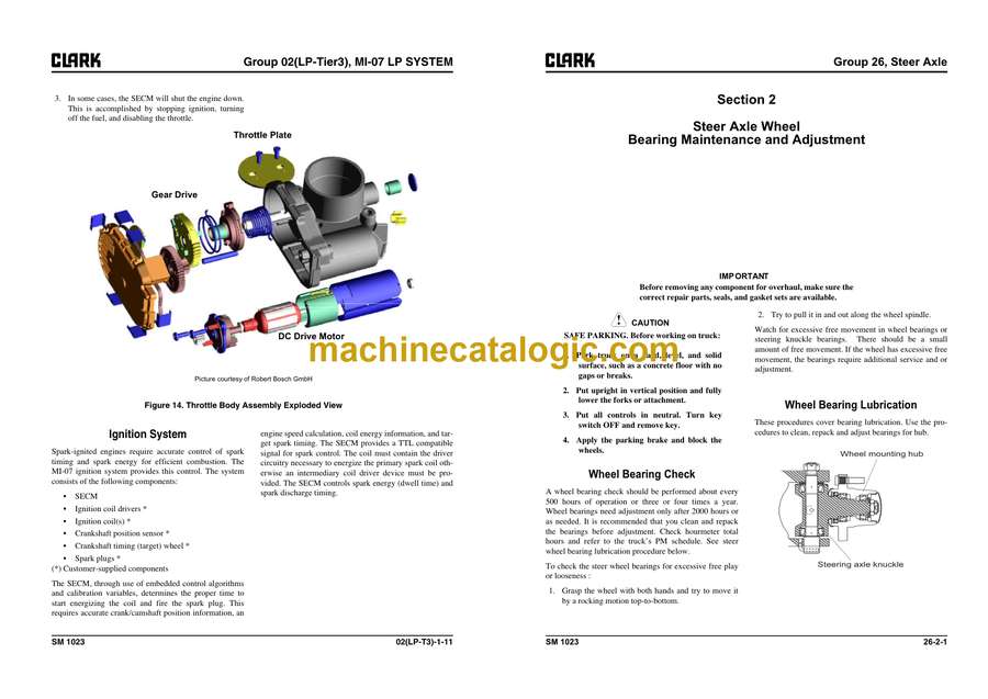
GROUP 02 (LP-TIER3) MI-07 LP SYSTEM (GM V6 4.3)
Section 0 REGULATORY COMPLIANCE
Section 1 LPG SYSTEM OVERVIEW
Section 2 SPECIFICATIONS
Section 3 RECOMMENDED MAINTENANCE
Section 4 INSTALLATION PROCEDURES
Section 5 TESTS AND ADJUSTMENTS
Section 6 BASIC TROUBLESHOOTING
Section 7 ADVANCED DIAGNOSTICS
Section 8 PARTS DESCRIPTION
GROUP 02 (GM-TIER4) PSI FUEL SYSTEM (GM V6 4.3)
Section 1 General Information
Section 2 Maintenance
Section 3 LPG Fuel System
Section 4 GASOLINE Fuel System
Section 5 Fuel System Diagnosis
Section 6 Electrical Section
Section 7 Definitions
GROUP 03 INTAKE AND EXHAUST SYSTEM
Section 1 Intake and Exhaust Systems Specifications and Description
Section 2 Intake System Troubleshooting
Section 3 Intake System Service
Section 4 Exhaust Systems
GROUP 07 TRANSMISSION – Model : 3WG-94EC (for Diesel truck)
Section 1 LAYOUT 3WG-94EC
Section 2 Measuring Points And Connections
Section 3 Disassembly
Section 4 Reassembly
Section 5 Transmission Removal and Installation
Section 6 AEB Setting of T/M Controller Clutch & Inching Calibration
Section 7 Troubleshooting
GROUP 08 TRANSMISSION (T12313 MODEL) (FOR LPG TRUCK)
Section 1 DISASSEMBLY
Section 2 DISASSEMBLY AND REASSEMBLY OF 1st AND 2nd CLUTCH
Section 3 DISASSEMBLY AND REASSEMBLY OF 3rd CLUTCH
Section 4 DISASSEMBLY AND REASSEMBLY OF FORWARD AND REVERSE CLUTCHES
Section 5 REGULATOR VALVE DISASSEMBLY AND REASSEMBLY
Section 6 CLEANING AND INSPECTION
Section 7 TROUBLESHOOTING PROCEDURES
Section 8 TRANSMISSION CONTROLLER
Section 9 TRANSMISSION REMOVAL AND INSTALLATION
GROUP 13 ELECTRICAL SYSTEM
Section 1 Cautions for working on the electrical system
Section 2 Electrical system Specifications and features
Section 3 Electrical Circuit Diagram & Electrical Parts Arrangement
Section 4 Instrument Pod
Section 5 Air Conditioning System (Option)
GROUP 20 (D) DRIVE AXLE (for Diesel truck)
Section 1 System Operation
Section 2 Differential Carrier Assy
Section 3 Drive Axle
Section 4 Problem and Cause
Section 5 Drive Axle Disassembly and Reassembly
Section 6 Transmission Removal and Installation
GROUP 21 (L) DRIVE AXLE (for LPG truck)
Section 1 System Operation
Section 2 Differential Carrier Assy
Section 3 Drive Axle
Section 4 Problem and Cause
Section 5 Disassembly and Reassembly of Drive Axle
Section 6 Transmission Removal and Installation
GROUP 22 WHEELS AND TIRES
Section 1 Wheels and Tires Specifications and Description
Section 2 Pneumatic Wheels and Tires
GROUP 23 BRAKE SYSTEM
Section 1 Braking / Inching System Specifications and Description
Section 2 Service Brake Troubleshooting
Section 3 Brake/Inching Pedals and Linkages Adjustments
Section 4 Brake System Bleeding
Section 5 Brake Valve Service
Section 6 Parking Brake Service
GROUP 25 STEERING COLUMN AND GEAR
Section 1 Steering System Specifications and Description
Section 2 Steering System Troubleshooting
Section 3 Steering Column and Component Removal and Replacement
Section 4 Steering System Relief Pressure Check and Adjustment
Section 5 Steering Gear Overhaul
GROUP 26 STEER AXLE
Section 1 Steer Axle Specifications and Description
Section 2 Steer Axle Wheel Bearing Maintenance and Adjustment
Section 3 Steer Axle Removal and Replacement
Section 4 Steer Axle Overhaul
Section 5 Steer Cylinder Removal and Replacement
Section 6 Steer Cylinder Overhaul
GROUP 29 HYDRAULIC SUMP, FILTERS, AND PUMP
Section 1 Main Hydraulic Sump, Filters, and Pump Specifications and Description
Section 2 Main Hydraulic Pump Troubleshooting
Section 3 Main Hydraulic Removal and Installation
GROUP 31 HYDRAULIC CONTROL VALVE
Section 1 Operation of Hydraulic Control Valve
Section 2 Hydraulic Circuit
Section 3 Disassembling Hydraulic Valve
Section 4 Assembling Hydraulic Control Valve
Section 5 Hydraulic System Pressure Checks and Adjustments
Section 6 Hydraulic Control Valve Removal and Replacement
Section 7 Testing Hydraulic Valve
Section 8 EHL Valve Disassembly and Assembly
GROUP 32 TILT CYLINDERS
Section 1 Tilt Cylinder Specifications and Description
Section 2 Tilt Cylinder Checks and Adjustments
Section 3 Tilt Cylinder Removal and Replacement
Section 4 Tilt Cylinder Overhaul
GROUP 34 UPRIGHTS
Section 1 Upright Specifications and Description
Section 2 Troubleshooting
Section 3 Upright Inspection
Section 4 Carriage and Upright Roller Clearance Checks and Shim Adjustments
Section 5 Cylinder Removal, Shimming, Overhaul, and Replacement
Section 6 Upright Chain Inspection, Adjustment, and Replacement
Section 7 Fork and Carriage Removal and Replacement
Section 8 Upright Removal and Replacement
GROUP 38 COUNTERWEIGHT AND CHASSIS
Section 1 Counterweight Specifications and Description
Section 2 Counterweight Removal and Replacement
Section 3 Overhead Guard/Operator’s Cell Removal and Replacement
Section 4 Floorboard, Cowls, and Seat Deck Removal and Replacement
Section 5 Operator’s Seat Removal and Replacement
GROUP 40 SPECIFICATIONS
Section 1 Nameplates and Decals
Section 2 General Specifications
Section 3 Hydraulic Fitting Tightening Procedure
