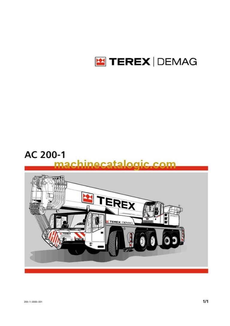
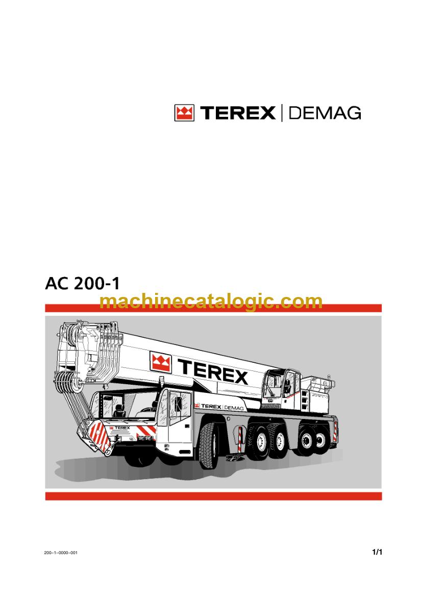
The Demag AC 200-1 is a multi-axle all terrain crane. It drives on public roads, then works on site with a telescopic boom. A rental or fleet company reaches for this full manual set when it wants every document for one model in one place, so operators, mechanics and the parts desk all work from the same source.
What this manual set helps you do
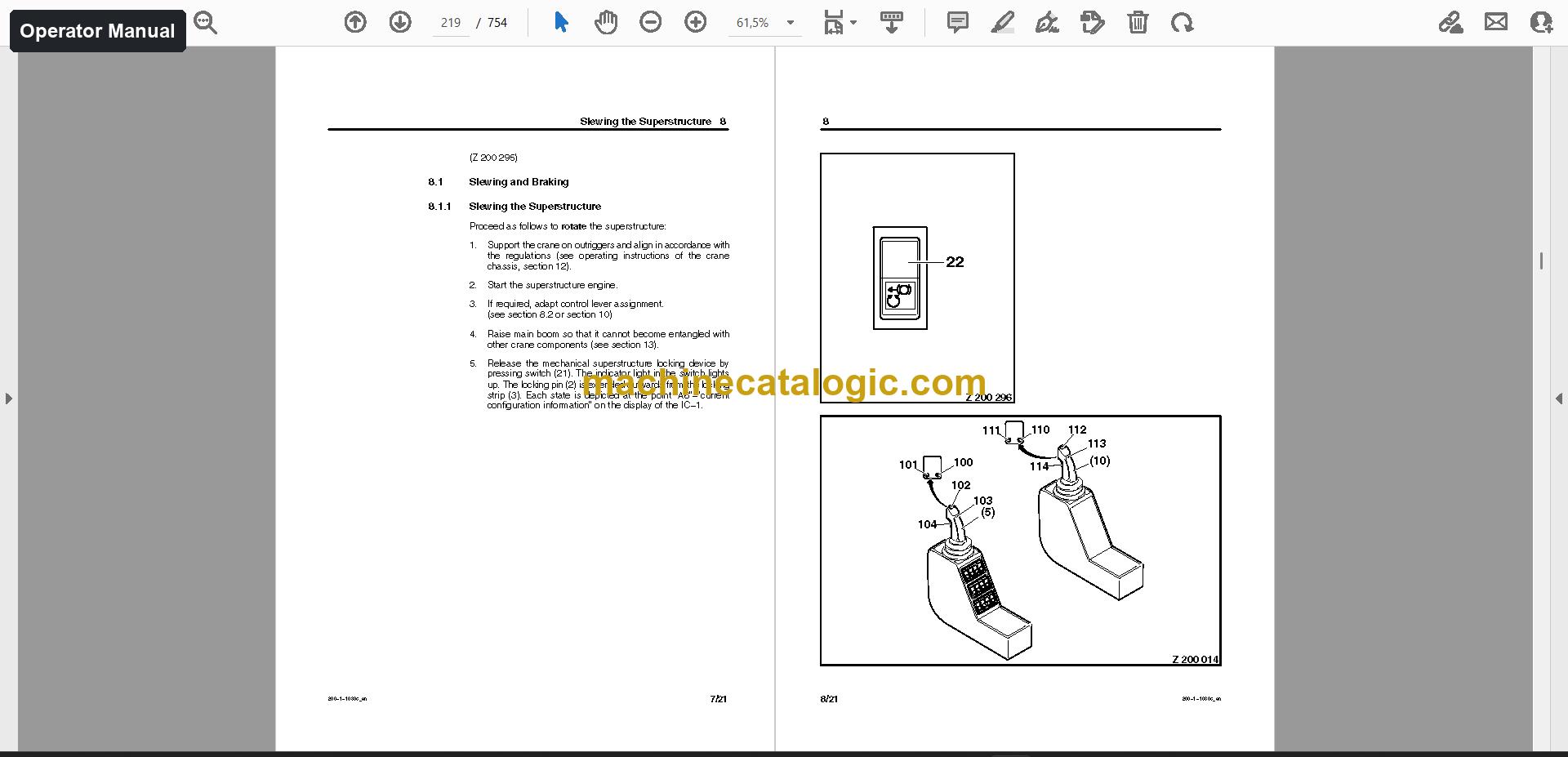
- Operate the crane by following the operator manual, which covers controls, setup, safe operation and daily checks.
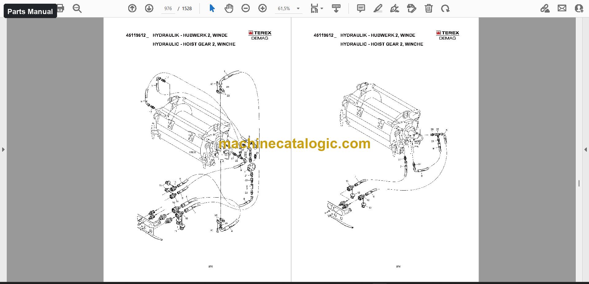
- Order the right components from the parts manual, which has exploded views and part numbers.
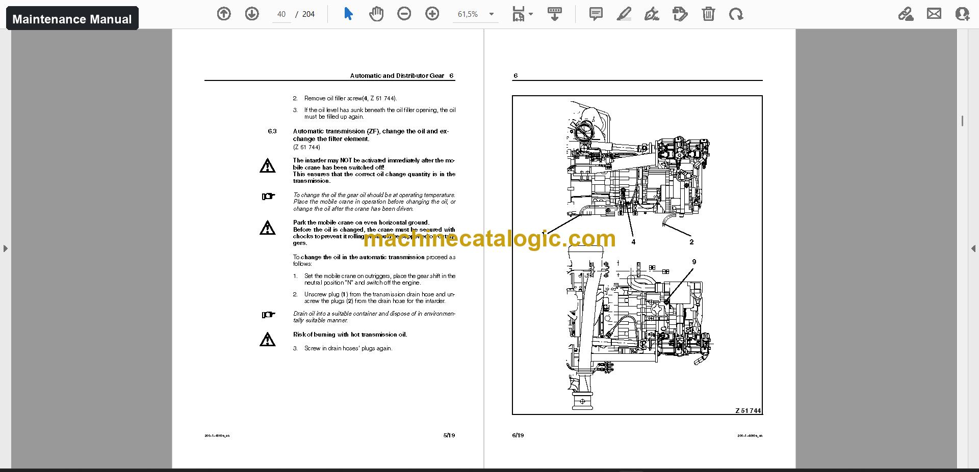
- Lubricate the superstructure and chassis on schedule using the maintenance manual, which sets out service intervals, lubrication and inspections.
- Trace hydraulic and electrical circuits with the schematics when you're fault-finding.
- Plan lifts with the load charts that come in the set.
Who this is for
A rental fleet manager can hand each department the documents it needs for the same machine. A workshop or service company gets the maintenance manual, schematics, diagnostic documents and component manuals together for work on the hydraulic system and electrical system.
FAQ
Q: What do I receive and how is it organised?
A: One download with 253 files (219 PDF) and 9,118 PDF pages in total. The operator manual is 1,500 pages in 5 files, the parts manual is 1,528 pages in 1 file, and the maintenance manual is 512 pages in 2 files. Documents are in English and German.
Q: Which machine does it fit?
A: The Demag AC 200-1 all terrain crane. The parts manual is titled AC 200-1 Spare Parts Catalogue, and the maintenance manual is split into the AC 200-1 Superstructure Lubrication Manual and AC 200-1 Chassis Lubrication and Maintenance.
Q: How does it fit my job?
A: The set also includes 103 schematics files, training documents, service information, assembly and installation files, and component manuals from Bosch Rexroth, Inter Control and Mobil Elektronik. Whether you're running the crane, servicing it or ordering parts, you'll find the matching document in the same download.
Keep the whole AC 200-1 documented in one place, from daily operation to parts ordering and lubrication.
📘 Show Index
Table of Contents:
Operator Manual Table of Contents
1,500 pages, 5 files
- Publication AC200-1-33175-Part1 (754 pages)
- Manufacturer's Specifications
- Foreword
- Safety Instructions
- General
- Intended Use
- Operating Conditions and Computed Design of the Crane
- Structure of the Crane
- Dimensions
- Overview
- Superstructure
- Crane operator's cab
- Controls and Displays
- leaving the cab
- Tilting the Cab
- Engine
- Engine control/monitoring
- Starting
- Jump starting
- Supporting the crane on outriggers from the crane operator's cab
- Slewing the Superstructure
- Slewing and Braking
- Control Lever Assignment
- Slewing Speed
- Counterweight
- Important Assembly Instructions
- Operating elements
- Assembling the counterweight
- Safety Equipment
- Electronic Crane Information System
- Control and Display Elements
- Operation of the IC-1
- Publication 140-1100_en (136 pages)
- Manual 2 (586 pages)
- Safety Instructions
- Transporting the Crawler−mounted Crane
- General
- Dimensions and Transport Weights of the Main Components
- Dimensions and Transport Weights of the Boom System
- Assembling and Dismantling the Crane
- General
- Assembling the Crane
- Assemble the chassis outrigger
- Assembling the Main Boom
- General
- Assembling and Fitting the Main Boom SH
- Assembling and Fitting the Main Boom SH/LH
- Assembling the Main Boom and Fly Jib
- General
- Assembling and Fitting Fly Jib Combination SW
- Assembling and Dismantling the Superlift
- General
- Assembling and Fitting the Superlift Mast
- Fitting the Superlift Mast with Telescopic Connection to the
- Assembling the Main Boom with Superlift
- General
- Assembling and Fitting the SSL Superlift Combination
- Assembling and Fitting the SSL/LSL Main Boom
- Assembling the Main Boom and Fly Jib with Superlift
- General
- Assembling and Fitting the Boom Combination SWSL
- Reeving the Ropes
- General
- Reeving the Derricking Ropes
- Reeving the Luffing Ropes
- Erecting and Lowering the Boom System
- General
- Erecting Boom Variant SH
- Erecting the Boom Variant SH/LH
- Hydraulic Power Pack with Pin Locking Cylinder
- General
- Starting the Hydraulic Power Pack
- Actuation of the Pin Locking Cylinder
- Manual 4 (24 pages)
Parts Manual Table of Contents
1,528 pages, 1 file
- Maintenance Parts
- Filter
- Mounting Parts
- Combi Box
- Door
- Wooden Support
- Spare Wheel Holder
- Hoist For Sparewheel
- Trailer Coupling
- Coupling Spring
- Draw Bar Coupling
- Hook Block Support
- Drive
- Drive Unit
- Engine Diesel
- Gear Box
- Gear Box Housing
- Input Shaft
- Main Shaft
- Return
- Gearshift System
- Gv-shift System
- Planetary Drive
- Gp-shift System
- Control Unit
- Pump
- Seal Kit
- Valve
- Hydr. Pump
- Hydr.pump
- Control Valve
- Oil Filler
- Cooling System
- Cooling Water Lines
- Expansion Tank
- Fuel System
- Fuel-water Separator
- Fuel Tank
- Fuel System Standard With Add. Tank
- Electric Stop Ac200-1
- Mounting Exhaust System
- Silencer Kit
- Brake / Pneumatic
- Air Pressure System
- Air Dryer
- Hydraulic, 5a
- Hydraulic Oil Tank
- Hydr. Oil Tank
- Return Filter
- Hydraulic, Main Pump I / Control Block
- Valve Block Suspension
- Hydraulic – Main Pump Ii
- Hydraulic – Emergency Steering Pump
- Hydraulic Suspension, Box R.h
- 2/2 Way Directional Seat Valve
- Hydraulik Suspension, Box L.h
- Hydraulic Suspension, Cylinder R.h
- Hydraulic Suspension, Cylinder L.h
- Hydraulic Steering, Box L.h
- Hydr. Unit
- Directional Spool Valve
- Coupling Sleeve
- Hydraulic – Steering Circuit I, 1 And 2
- Hydraulik – Steering Circuit I, 3 And 4
- Hydraulic – Steering Circuit I, A4
- Hydraulic – Steering Circuit I, A5
- Hydraulik – Steering Circuit Ii, 1 And 2
- Hydraulic – Steering Circuit Ii, 3 And 4
- Outrigger Hydraulik, Control Block
- Control Block
- Outrigger Hydraulic, Cylinder Rear
- Outrigger Hydraulic, Cylinder Front
- Emergency Control
- Hydraulic – Emergency Control
- Additional Parts Emergency Control
- Hydraulic Transformer
- Hydraulic Motor
- Hydraulic Pipes For Transformer
- Drivers Cab
- Drivers Cabin, Mounting
- Cab Chassis 2880 Cpl
- Door L.h
- Keys And Locking Cylinder For Cabin
- Door R.h
- Wiper Equipment
- Covering
- Lock Pin
- Window Shade
- Electric Cab
- Pipe Connection Cab
- Heater Assembly
- Mounting Parts Cab Chassis
- Seat
- Rear Part Mounting L.h
- Rotaflare Light
- Front Bumper
- Undercarriage-mirrors
- Exterior Mirror
- Panoramic Mirror
- Steering Column
- Steering Wheel
- Ignition Switch
- Engine Independent Heater
- Heater
- Air Conditioning
- Climatic Arr. Cab Chassis
- Push-toggle Switch
- Cab Electric
- Lamp
- Digsy Comp. Chassis
- Mounting Hinged Bed
- Electric
- Fuse Box
- Slip Ring, Mounting
- Operation Box Outrigger System
- Lighting Equipment, R.h.-drive
- Underride Guard
- End Light
- Tail Light
- Lighting Equipment, L.h.-drive
- Lights Support Li Lv Ac120/100
- Lights Support Re Lv Ac120/100
- Support Base Detection
- Electric Abs 3. Axle Chassis Cpl
- Grease Equipment
- Lubrication Pump
- Harness Lube System
- Outriggers
- Outrigger, Front
- Outriggercylinder Front
- Horizontal Cylinder
- Outrigger, Rear
- Outrigger Cylinder
- Operation Box Outriggers Without Cgm
- Support Plate
- Mounting – Axles, 5a
- Suspension Cylinder
- Axle 1
- Steering Axle
- Brake,r.h
- Brake Shoe With Lining
- Expanding Cylinder
- Brake, Left Hand
- Steering Cylinder
- Hose
- Axle 2
- Steering Drive Axle
- Axle Drive
- Brake, Right
- Brake, Left
- Planetary Gear
- Pre-assembly Axle 3
- Steering Pump
- Hose Pre Assembly
- Pre Assembly
- Brake, Assy
- Steering-cylinder
- Distributor Gear
- Mounting – Joint Shafts
- Mounting Of Steering Assy Usa
- Steering
- Replenish. Valve
- Wheel
- Superstructure
- Covering Drive Arrangement
- Covering Control Unit Superstructure
- Rail Superstructure Ac 200-1
- Mirror’s
- Mirror
- Slew Gear
- Mounting – Drehwerk
- Hydraulic Engine
- Power Unit
- Hydraulic – Slew Gear
- Slew Ring
- Superstructure – Locking
- Cylinder
- Hydraulic-superstructure Locking Devic
- Slew Ring Transmitter, Mounting
- Drive Block Assy
- Pump Group
- Gear Pump Assy
- Modulation Control
- Shuttle Valve
- Flange With Access
- Hydr. Pump, Assy
- Pressure Relief Valve
- Gear Pump Kit
- Gear Pump
- Wear Plate
- Piston With Non-return Valve
- Diesel Engine
- Pre-assembly – Cooling System
- Suction Adapter
- Air Filter
- Stop Superstructure
- Exhaust System
- Filter Unit Superstructure Ac200-1
- Diesel – Fuel Pump ( Man. )
- Winches / Hoist Gears
- Mounting Hoist Gear 1 With Rope U Fitti
- Hoist Gear With Rope U Fitting 34
- Hoist Gear Assy
- Rope Drum
- Bearing Bush
- Disc Brake
- Oil Level Gauge
- Built-in Gear
- Transmission
- Lowering Brake Valve
- Rope Fixing Hoist Gear
- Hydraulic – Hoist Gear 1
- Mounting Hoist Gear 2 With Rope U Fitti
- Kit Electric Hoist Gear 2
- Mounting Aid
- Wiring Harness Hoist 2
- Hoist Limit Switch
- Hydraulic – Hoist Gear 2, Winche
- Hydraulic – Hoist Gear 2, Control Blocks
- Counterweights, Mounting
- Add. Counterweights, Mounting
- Counterweight – Lift Cylinder, Mounting
- Luffing Cylinder
- Final Assembly Luffing Cylinder
- Brake Valve
- Hydraulic – Luffing Cylinder
- Mounting – Main Boom
- Hydraulic
- Mounting Hy-tank Superstructure
- Pre Assembly Hydraulic Tank Superstruc
- Hydraulic Tank Sk Cpl
- Return Oil Filter
- Oil Cooler
- Hydraulic – Oil Cooler
- Pressure Filter
- Hydraulic – Pump 140
- Hydraulic – Pump 40
- Hydraulic – Pump 29
Maintenance Manual Table of Contents
512 pages, 2 files
- Safety Instructions
- Transporting the Crawler−mounted Crane
- General
- Dimensions and Transport Weights of the Main Components
- Dimensions and Transport Weights of the Boom System
- Assembling and Dismantling the Crane
- General
- Assembling the Crane
- Assemble the chassis outrigger
- Assembling the Main Boom
- General
- Assembling and Fitting the Main Boom SH
- Assembling and Fitting the Main Boom SH/LH
- Assembling the Main Boom and Fly Jib
- General
- Assembling and Fitting Fly Jib Combination SW
- Assembling and Dismantling the Superlift
- General
- Assembling and Fitting the Superlift Mast
- Fitting the Superlift Mast with Telescopic Connection to the
- Assembling the Main Boom with Superlift
- General
- Assembling and Fitting the SSL Superlift Combination
- Assembling and Fitting the SSL/LSL Main Boom
- Assembling the Main Boom and Fly Jib with Superlift
- General
- Assembling and Fitting the Boom Combination SWSL
- Reeving the Ropes
- General
- Reeving the Derricking Ropes
- Reeving the Luffing Ropes
- Erecting and Lowering the Boom System
- General
- Erecting Boom Variant SH
- Erecting the Boom Variant SH/LH
- Hydraulic Power Pack with Pin Locking Cylinder
- General
- Starting the Hydraulic Power Pack
- Actuation of the Pin Locking Cylinder
Also in this set
- Schematics (103 files, 3,189 pages)
- Load charts (2 files, 62 pages)
- Technical data (16 files, 10 pages)
- Service information (1 file, 39 pages)
- Assembly and installation (68 files, 69 pages)
- Diagnostic documents and software (9 files, 333 pages)
- Training documents (20 files, 388 pages)
- Component manuals (13 files, 1,488 pages)
- Bosch Rexroth
- Inter Control
- Mobil Elektronik
- Other documents (13 files)
Demag PDF Manuals
All Crane Manuals