A CC 2800 is a heavy-lift crawler crane that works long projects where a big load has to be set precisely and the machine stays on site for months. This full manual set is for the workshop that takes one in without any paperwork and has to service it properly. Everything for the machine comes in one download, so you aren't chasing single books halfway through a job.
What this manual set helps you do
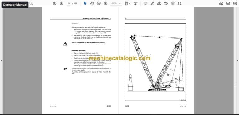
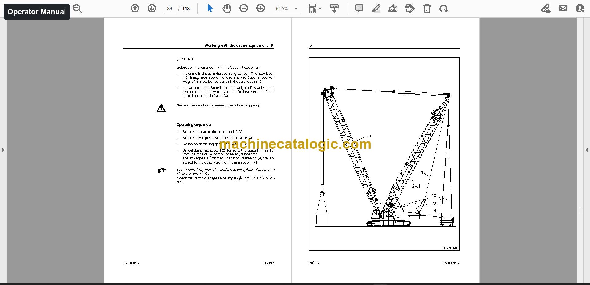
- Operate the crane safely by following the operator manual on the cab, engine and drive, driving the crawler-mounted crane, and daily checks.
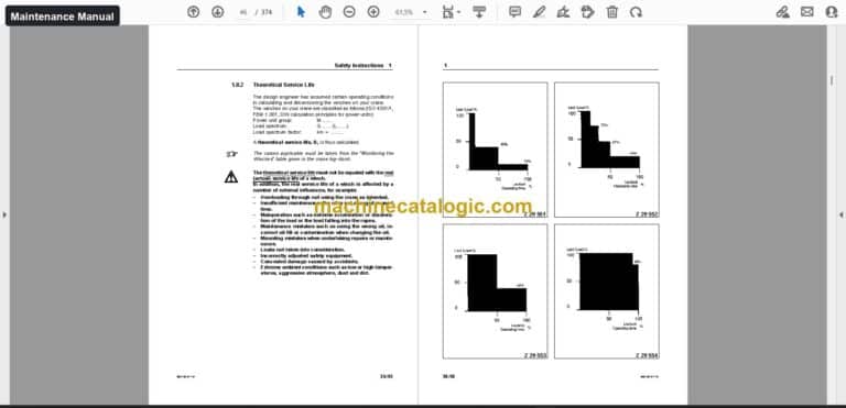
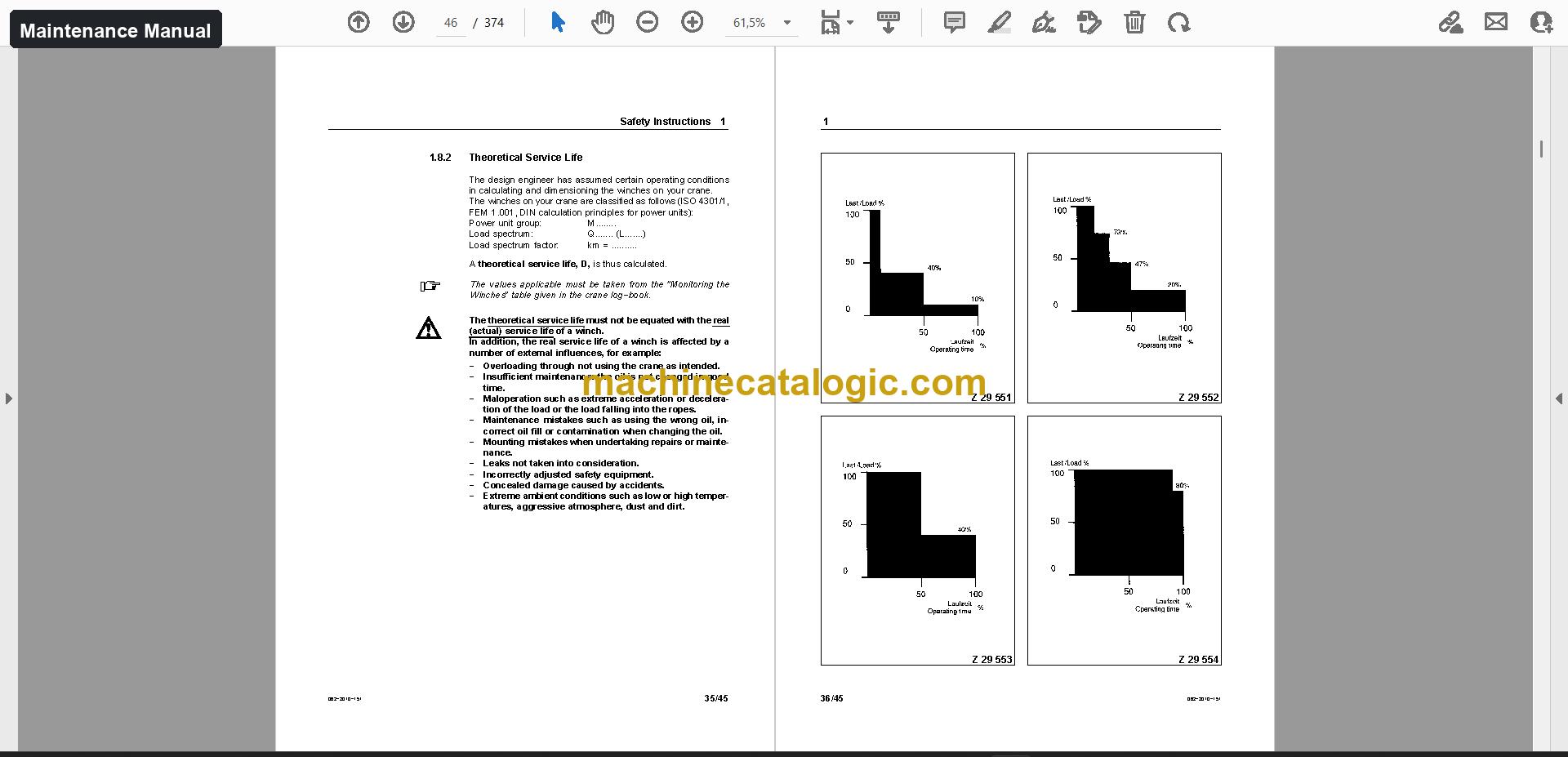
- Lubricate and inspect on schedule using the maintenance manual, which covers fuels and lubricants, the slew ring connection, slew gear, hoists and drive.
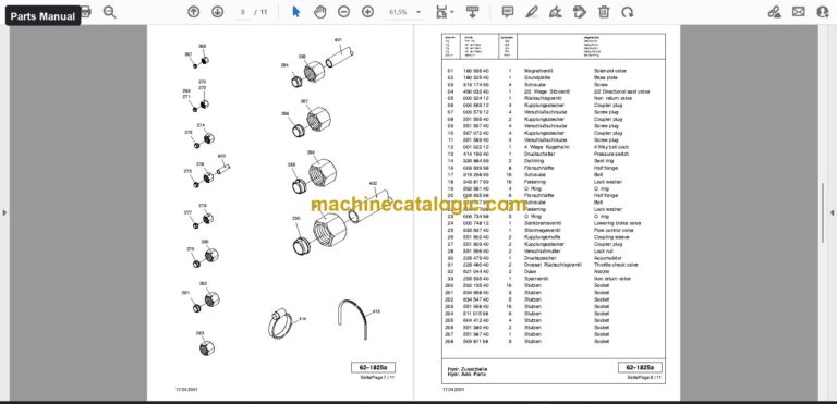
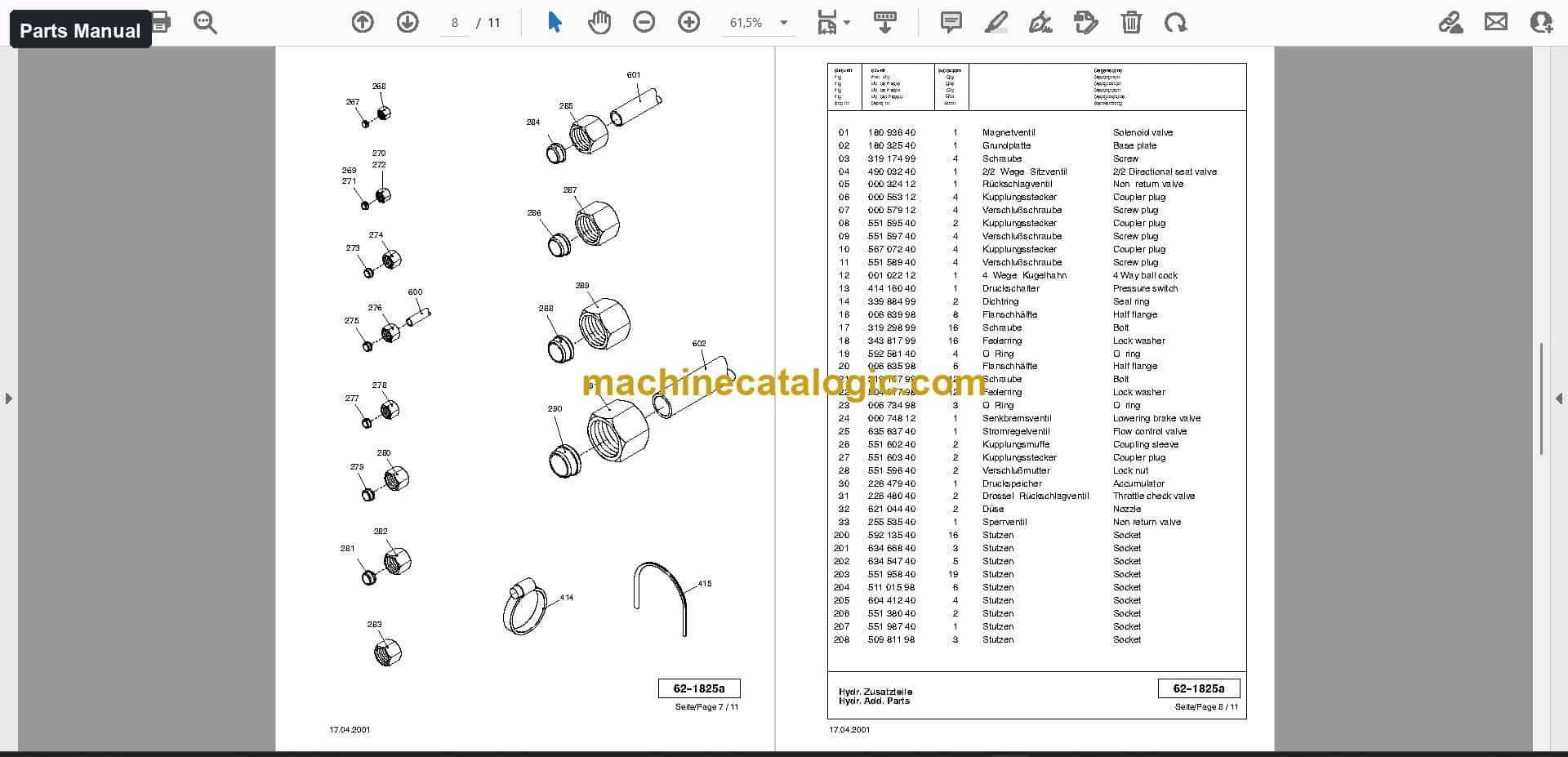
- Order the right components from the parts manual, with sections such as undercarriage, engine, drive gear box, support cylinder and hydraulic transmission.
- Trace hydraulic and electrical circuits in the schematics when you're fault-finding.
- Verify lifting set-ups against the load charts and the load moment indicator component manuals.
Who this is for
A workshop or service company taking over a used CC 2800 gets the whole documentation for the machine in one place. A rental fleet manager can hand operators, mechanics and the parts desk the same set.
FAQ
Q: What do I receive and how is it organised?
A: One download with 1,653 files (1,008 PDF) and 30,195 PDF pages. The operator manual is 2,244 pages in English, Dutch, French and German, the parts manual is 5,781 pages in German and English, and the maintenance manual is 1,496 pages in French, German, English and Dutch.
Q: Which machine does it fit?
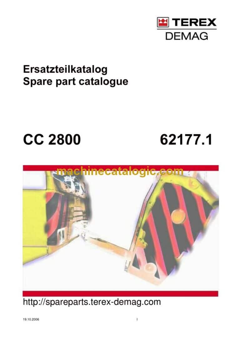
A: The Demag CC 2800 crawler crane. The serial number printed on the main manual cover is 62173, so you can compare it with your machine's plate.
Q: How does it help with taking over a crane that has no paperwork?
A: You get the operator manual, parts manual, maintenance manual and schematics, plus assembly and installation, diagnostic documents, training documents and service information. That lets you set up a service plan, order parts and start fault-finding from one source.
If you work on a CC 2800, this set gives you the documents to operate, maintain, repair and order parts for it from one download.
Does this manual fit your machine?
| Model |
Serial No. |
| CC 2800 |
62173 |
The serial number shown is the one printed on the manual cover. Check the model and serial number on your machine's data plate before ordering.
📘 Show Index
Table of Contents:
Operator Manual Table of Contents
2,244 pages, 18 files
- Publication 062-1001-173 / Serial No. 62173 (450 pages)
- CC 2800 Manufacturer’s Specifications
- CC 2800 Operating Lubrication and Maintenance Instructions
- CC 2800 Safety Instructions and Operating Conditions
- CC 2800 Safety Instructions
- CC 2800 Crawler Crane Structure
- CC 2800 Crane Operator’s Cab
- CC 2800 Engine and Drive
- Driving the Crawler-Mounted Crane
- Slewing and Braking the Superstructure
- Operating the Safety Equipment
- Working with the Crane Equipment
- Operating the Heating and Ventilation
- Radio Remote Control
- Serial No. 62 151, 62151 (1,794 pages)
- Safety Instructions
- Transporting the Crawler−mounted Crane
- General
- Dimensions and Transport Weights of the Main Components
- Dimensions and Transport Weights of the Boom System
- Assembling and Dismantling the Crane
- General
- Assembling the Crane
- Assemble the chassis outrigger
- Assembling the Main Boom
- General
- Assembling and Fitting the Main Boom SH
- Assembling and Fitting the Main Boom SH/LH
- Assembling the Main Boom and Fly Jib
- General
- Assembling and Fitting Fly Jib Combination SW
- Assembling and Dismantling the Superlift
- General
- Assembling and Fitting the Superlift Mast
- Fitting the Superlift Mast with Telescopic Connection to the
- Assembling the Main Boom with Superlift
- General
- Assembling and Fitting the SSL Superlift Combination
- Assembling and Fitting the SSL/LSL Main Boom
- Assembling the Main Boom and Fly Jib with Superlift
- General
- Assembling and Fitting the Boom Combination SWSL
- Reeving the Ropes
- General
- Reeving the Derricking Ropes
- Reeving the Luffing Ropes
- Erecting and Lowering the Boom System
- General
- Erecting Boom Variant SH
- Erecting the Boom Variant SH/LH
- Hydraulic Power Pack with Pin Locking Cylinder
- General
- Starting the Hydraulic Power Pack
- Actuation of the Pin Locking Cylinder
Parts Manual Table of Contents
5,781 pages, 461 files
- Publication 62177.1 (1,752 pages)
- Undercarriage
- Pin Locking Unit
- Cylinder
- Seal Kit
- Hydraulic System Chassis Cc 2800-1
- Solenoid Valve
- Directional Spool Valve
- Coupling Sleeve
- Slip Ring Mounting
- Slip Ring
- Cylinder Head Bolt
- Electric Chassis
- Distribution Box
- Track Frame Duo 1500
- Drive Gear Box
- Brake Assy
- Hydraulic-motor
- Basic Pump
- Transmission Assy
- Shaft Seal
- Pump Displacement
- Control Unit
- Engine
- Transmission
- Intermediate Plate
- Brake Valve With Plate
- Track Adjusting Cylinder
- Lube Pump
- Parts Pre-assembly Bottom Plate 1500 Mm
- Tool For Undercarriage
- Tl Handpumpe For Chainnbracing Cylinder
- Outriggers Cpl
- Support Cylinder
- Support Plate
- Support Chassis Cc 2800-1
- Cable
- Stop Mounting Track Frame
- Superstructure
- Mounting Parts
- Mirror
- Pin-locking Cylinder
- Cat Walks Superstructure
- Fold-away Step
- Add. Cat Walks For Superstructure
- Mounting Cat Walks Engine And Oil Cooler
- Catwalks Engine And Oil Cooler
- Mounting Support
- Slew Ring
- Mounting Slew Gear
- Hydraulic Engine
- Transmission Consist. Of Fig-nos: 09,16
- Transmission, Hydr. Pice
- Slew Gear
- Oil Drain Socket
- Drive
- Diesel Engine
- Filter Element
- Water Pump
- Compressor
- Pump Distributor Gear
- Variable Displacement Pump
- Hydraulic Transmission
- Connector Plate
- Governor Unit
- Flanged Nut
- O-ring
- Carrier, Pump
- Shuttle Valve
- Pump Combination
- Hydr. Pump, Assy
- Control Valve
- Hydr. Pump
- Gear Pump
- Hydr.-pump
- Transmission, Assy
- Pressure Valve
- Pressure Relief Valve
- Shut Down Valve
- NUT
- Gear Pump Kit, Assy
- Modulation Control, Assy
- Filter Mounting
- Filter Head
- Spring
- Suction Line
- Hydraulic Oil Tank
- Cover (for Cleaning)
- Cooling System
- Mounting Air Intake Pipe
- Cooling Flange Ow-engine
- Air Filter Mounting
- Air Filter
- Mounting Tank
- Expansion Tank
- Fuel Tank
- Fuel System
- Fuel-water Separator
- Exhaust System
- Parts Ass. Muffler
- Oil Cooler Cpl
- Oil Cooler
- Hydraulic Pump
- Power Unit, Assy
- Mounting Winch
- Winch
- Winch Gear
- Seal Ring
- Control Unit, Assy
- Cover Assy
- Elektric Winch
- Induction Switch
- Return Parts W1 At Superstructur
- Derricking Gear
- Sheave
- Torsion Shaft 60t
- Rope Protection
- Place Of Deposit
- Reeving Winch
- Power Unit
- Brake Modifications Kit 11 Chassis 06
- Hydraulic System Reeving Winch
- CAB
- Mounting Cab Superstructure
- Electric Cab
- Wiper Roof
- Rotaflare Light
- Heater
- Metering Pump
- Hose Clip
- Fuel Filter
- Harness
- Exhaust Hose
- Filter
- Parts Air Conditioning Equipment Zur Cab
- Driver’s Seat
- Seat Assy
- Electric Seat Driver
- Push-toggle Switch
- Lamp
- Pilot Control Lever
- Electric Leteral Console Mounting
- Switch
- Electric Console
- Indicator Light Module
- Mounting Plate
- Platform
- PIN
- Air Conditioning Equipment
- Counterweight
- Hydraulic
- Hydr. System Pre-assembly Carrier
- Control Block
- Valve
- Hydr. System Add. Parts
- Hydraulic -hoses For Hydr. System Additi
- 2/2 Way Directional Seat Valve
- Hydr. System Oil Cooler
- Hydr. System Pump Tubes Cc 2800-1
- Hydr. System Add. Parts Cc
- Pre-control Valve
- Hydr. System Preparation Counterweight
- Hydr. System Support Pre-assembly
- Hydr. System Add. Parts Pre-assembly
- Hydraulic -hoses F Hydr. System H3 13161
- Electric Süperstructure
- Electric Superstructure
- Remote Control
- Socket Box
- Distribution Box Engine
- Fuse Box
- Socket Plate Cpl
- Camera Mounting Superstructure
- Add. Electric Superstructure Sl-gw
- Adapterset Cable 18/16
- Safety Decals Ce
- UNTERWAGEN / UNDERCARRIAGE
- Publication 62254.1 (1,154 pages)
- Undercarriage
- Mounting Parts
- Stop Mounting Track Frame
- Counterweight
- Pin Locking Unit
- Cylinder
- Seal Kit
- Arrangement Slip Ring
- Drive Gear Box
- Carrier Assy
- Planetary Carrier Cpl
- Hydraulic-motor
- Basic Pump
- Transmission Assy
- Shaft Seal
- Pump Displacement
- Control Unit
- Engine
- Transmission
- Intermediate Plate
- Brake Valve With Plate
- Track Adjusting Cylinder
- Drive Gear Box F700 L.h.cpl With Brake
- Lube Pump
- Outriggers Assembly
- Outrigger Assembly
- Support Cylinder
- Support Plate
- Electric
- Electrical Crawler 24p
- Distribution Box
- Cable
- Cable Extension
- Electric Refueling Equipment
- Hydraulic
- Hydraulic Undercarriage Cc 2800-1
- Solenoid Valve
- Directional Spool Valve
- Coupling Sleeve
- Hydraulic Trac Frame Cc 2800-1
- Hydraulic Outriggers Undercarriage Cc 28
- Superstructure
- Mirror
- Pin Locking Main Boom
- Hydraulic Cylinder The 80/50 X 345
- Add. Cat Walks For Superstructure
- Fold-away Step
- Slew Ring
- Mounting Slew Gear
- Hydraulic Engine
- Cylinder Head Bolt
- Transmission Consist. Of Fig-nos: 09,16
- Transmission, Hydr. Pice
- Slew Gear
- Oil Drain Socket
- Premounting Drive
- Engine Om 502 La
- Oil Pump
- Compressor
- Filter Element
- Pump Distributor Gear
- Variable Displacement Pump
- Hydraulic Transmission
- Connector Plate
- Governor Unit
- Flanged Nut
- O-ring
- Carrier, Pump
- Shuttle Valve
- Pump Combination
- Hydr. Pump, Assy
- Control Valve
- Gear Pump
- Hydr. Pump
- Transmission, Assy
- Pressure Valve
- Pressure Relief Valve
- Shut Down Valve
- NUT
- Gear Pump Kit, Assy
- Filter System
- Filter Assy
- Filter Head
- Drive
- Hydraulic Pump
- Power Unit, Assy
- Suction Line
- Hydraulic Oil Tank
- Filter
- Return Oil Filter
- Cover (for Cleaning)
- Vm Cooling System
- Mounting Air Intake Pipe
- Air Filter Mounting
- Air Filter
- Mounting Box
- Water Equalizing Tank
- Fuel Tank
- Fuel System
- Fuel-water Separator
- Exhaust System Cc2800
- Parts Ass. Muffler
- Oil Cooler Cpl
- Oil Cooler
- Elektric Aux Heating System Cc 2800
- Mounting Refueling Pump Cpl
- Refueling Pump
- Cab Superstructure 1200, Cpl
- Cabin Superstructure 1200 Aurora
- Pump
- Electric Cab
- Wiper Roof
- Rotaflare Light
- Heater Cpl
- Heater
- Metering Pump
- Air Conditioning Unit
- Covering Parts, Cab 1200
- Seat
- Seat Support
- Platform With Railing For Cabine
- Flod Away Step
- Air Conditioning Equipment
- Control Block
- Valve
- Remote Control Manifolds
- Pressure Reducing Valve
- Hydraulic Add. Parts Pre-assembly
- Hoses For Add. Parts Pre-assembly Cc
- Hydr. System Oil Cooler
- Hoses Superstructure Cc 2800-1
- Hoses For Pump Tubes Cc 2800-1
- Pre-control Valve
- Hydraulic Hose F. H-system Add. Parts C
- Hoses For Preparation Slgw
- Hoses Mast Support Superstructure
- Return Parts W1 At Superstructur
- Electric Pressure Transducer
- Socket Box
- Fuse Box
- Electric Leteral Console
- Switch
- Push-toggle Switch
- Lamp
- Electric Leteral Console Installation Ca
- Circuit Plate
- Electric Seat Driver
- Pilot Control Lever
- Electric Air Conditioning Equipment
- Electric Derricking Gear
- Emergency Control System Remote
- Limit Switch Arr. A-frame
- Limit Switch Arr
- Mounting Rotation Transducer
- Mounting Parts Electrical Superstr
- Mounting Load Cell
- Safety Decals Ce
- Add. Parts
- Counterweight 330t Decals And
- Sign For Operating Manual
- Mounting Winch H1/h2
- Winch
- Winch Gear
- Seal Ring
- Control Unit, Assy
- Cover Assy
- Hoist Gears At Superstructure
- Serial No. 62152, 62135 (2,875 pages)
- Undercarriage
- Pin Locking Unit
- Cylinder
- Seal Kit
- H-system Chassis Cc 2800-1
- Solenoid Valve
- Directional Spool Valve
- Coupling Sleeve
- Hoses Chassis Cc 2800-1
- Slip Ring Mounting
- Slip Ring
- Electric Chassis
- Distribution Box
- Track Frame
- Drive Gear Box
- Brake Assy
- Hydraulic-motor
- Basic Pump
- Transmission Assy
- Pump Displacement
- Control Unit
- Engine
- Transmission
- Intermediate Plate
- Brake Valve With Plate
- Track Adjusting Cylinder
- Lube Pump
- Outrigger Cpl
- Support Cylinder
- Support Plate
- H-diagram Outriggers Chassis Cc 2800-1
- Lubrication And Add. Materials Chassis
- Superstructure
- Mounting Parts
- Mirror
- Pin Locking Main Boom
- Hydraulic Cylinder The 80/50 X 345
- Fold-away Step
- Add. Cat Walks For Superstructure
- Slew Ring
- Mounting Slew Gear
- Hydraulic Engine
- Transmission Consist. Of Fig-nos: 09,16
- Transmission, Hydr. Pice
- Slew Gear
- Oil Drain Socket
- Drive
- Pump Distributor Gear
- Variable Displacement Pump
- Hydraulic Transmission
- Connector Plate
- Governor Unit
- Carrier, Pump
- Shuttle Valve
- Pump Combination
- Hydr. Pump, Assy
- Control Valve
- Hydr. Pump
- Gear Pump
- Hydr.-pump
- Transmission, Assy
- Pressure Valve
- Pressure Relief Valve
- Shut Down Valve
- Gear Pump Kit, Assy
- Modulation Control, Assy
- Filter Mounting
- Hydraulic Pump
- Power Unit, Assy
- Suction Line
- Hydraulic Oil Tank
- Return Oil Filter
- Cover (for Cleaning)
- Cooling System
- Mounting Air Intake Pipe
- Cooling Flange Ow-engine
- Air Filter Mounting
- Air Filter
- Mounting Box
- Expansion Tank
- Fuel Tank
- Fuel System
- Fuel-water Separator
- Exhaust System Cc2800
- Parts Ass. Muffler
- Oil Cooler Cpl
- Oil Cooler
- Reeving Winch
- Winch Gear
- Power Unit
- Mounting Cab Superstructure
- CAB
- Electric Cab
- Wiper Roof
- Rotaflare Light
- Heater
- Heater Assembly
- Parts Air Conditioning Equipment Zur Cab
- Covering Parts, Cab 1200
- Driver's Seat
- Seat Assy
- Platform
- PIN
- Air Conditioning Equipment
- Counterweight
- Hydraulic
- H-system Support Pre-assembly Cc 2800-1
- Control Block
- Valve
- Remote Control Manifolds
- Pressure Reducing Valve
- Hydraulic Add. Parts Pre-assembly
- Hoses For Add. Parts Pre-assembly Cc
- Cable
- Hydr. System Oil Cooler
- Hoses Superstructure Cc 2800-1
- Hoses For Pump Tubes Cc 2800-1
- Pre-control Valve
- Hydraulic Hose F. H-system Add. Parts C
- Hoses For Preparation Slgw
- Electric
- Electric Superstructure, With Superlift
- Monitoring System
- Fuse Box
- Electric Leteral Console
- Switch
- Push-toggle Switch
- Lamp
- Circuit Plate
- Electric Seat Driver
- Pilot Control Lever
- Monitoring Cab
- Electric Mounting Console 2 Dlog
- Safety Decals Ce
- Add. Parts
- Counterweight 330t Decals And
- Sign For Operating Manual
- Attachment
- A-frame
- Sheave
- Limit Switch Arr
- Hydraulic A-frame Support
- A-frame- Mounting Cylinder
- Main Boom
- Electric Main Boom Foot Section
- Head Adapter
- Mounting Limit Switch
- Limit Switch
- Rope Yoke
- Electric Roller Set
- Cable Reel
- Jib Top Section
- Cable Drum
- Bracing Rope
- Rope Deflector
- Outrigger Main Boom
- Outrigger Cylinder L.h
- Outrigger Cylinder R.h
- Rope Shackle
- Electric Runner
- Mounting Winch W1
- Winch
Maintenance Manual Table of Contents
1,496 pages, 4 files
- Publication 062-2002-151 (374 pages)
- Foreword
- Safety Instructions
- General
- Selection and Qualifications of Personnel
- Particular Hazards
- Fuels and Lubricants
- Lubrication and Maintenance Schedule
- Initial Lubrication and Maintenance
- Regular Routine Lubrication and Maintenance
- Tips for Maintaining the Crane
- Drive
- Engine
- Pump Distributor Gear – Checking the Oil Level
- Pump Distributor Gear – Changing the Oil
- Slew Ring Connection
- Lubricating the Slew Ring Connection
- Lubricating the Ring Gear
- Operational Reliability of the Fixing Bolts
- Slew Gear
- Slew Gear Mechanism, Checking the Oil Level
- Slew Gear Mechanism, Changing the Oil
- Checking the Brake
- Hoists
- Hoist 1 and 2 – Checking the Oil Level
- Hoist 1 and 2 – Changing the Oil
- Hoist 3 – Checking the Oil Level
- Luffing Gears
- Luffing Gear 1 – Checking the Oil Level
- Luffing Gear 1 – Changing the Oil
- Luffing Gear 2 – Checking the Oil Level
- Derricking Gear
- Derricking Gear – Checking the Oil Level
- Derricking Gear – Changing the Oil
- Checking the Derricking Gear Brakes
- Equipment
- Maintaining the Hydraulic Cylinders on the Superstructure and Equipment
- Lubricating the Boom Bearings
- Hook Blocks
- Hydraulic System
- Hydraulic Oil Reservoir – Checking the Oil Level
- Hydraulic Oil Reservoir – Replacing the Return Oil Filter
- Hydraulic Oil Reservoir – Replacing the Aeration Filter
- Heating
- Checking the System is Functioning Correctly
- Checking the Fuel Level
- Checking the Water Level
- Electrical System
- Checking the Lighting System
- Checking the Battery Fluid Level
- Checking the Limit Switches
- Serial No. 62 151 (374 pages)
- Serial No. 62 151 (374 pages)
- Serial No. 62151 (374 pages)
Also in this set
- Schematics (22 files, 1,276 pages)
- Load charts (568 files, 6,615 pages)
- Technical data (10 files, 82 pages)
- Service information (11 files, 11 pages)
- Assembly and installation (27 files, 3,797 pages)
- Diagnostic documents and software (12 files, 248 pages)
- Training documents (12 files, 8,137 pages)
- Component manuals (60 files, 508 pages)
- PAT DS 350 Load Moment Indicator
- PAT General Documents
- PAT modular PDC Load Moment Indicator
- CDs and software (134 files)
- Other documents (314 files)
Demag PDF Manuals
All Crane Manuals