$ 0
0
$ 0
0

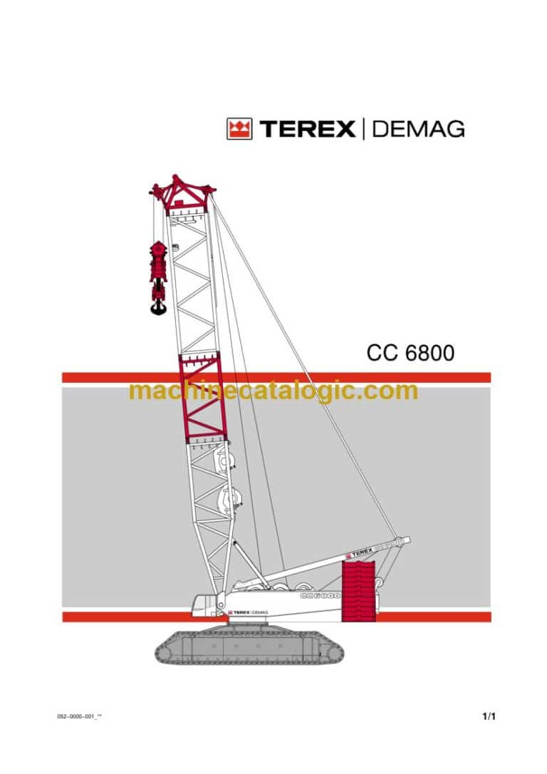
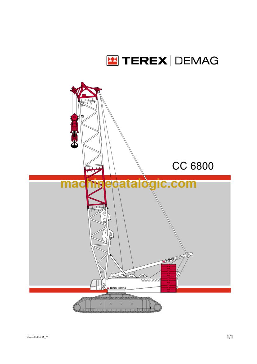
Demag CC 6800 Crawler Crane Full Manual (Operator, Parts, Maintenance, Schematics)

Format: PDF (Printable Document)

File Language: English, Dutch, German

File Pages: 144,082

File Size: 3.97 GB (Speed Download Link)

File Count: 2,129 files (1,843 PDF)

Brand: Demag

Model: CC 6800

Equipment Type: Crawler Crane

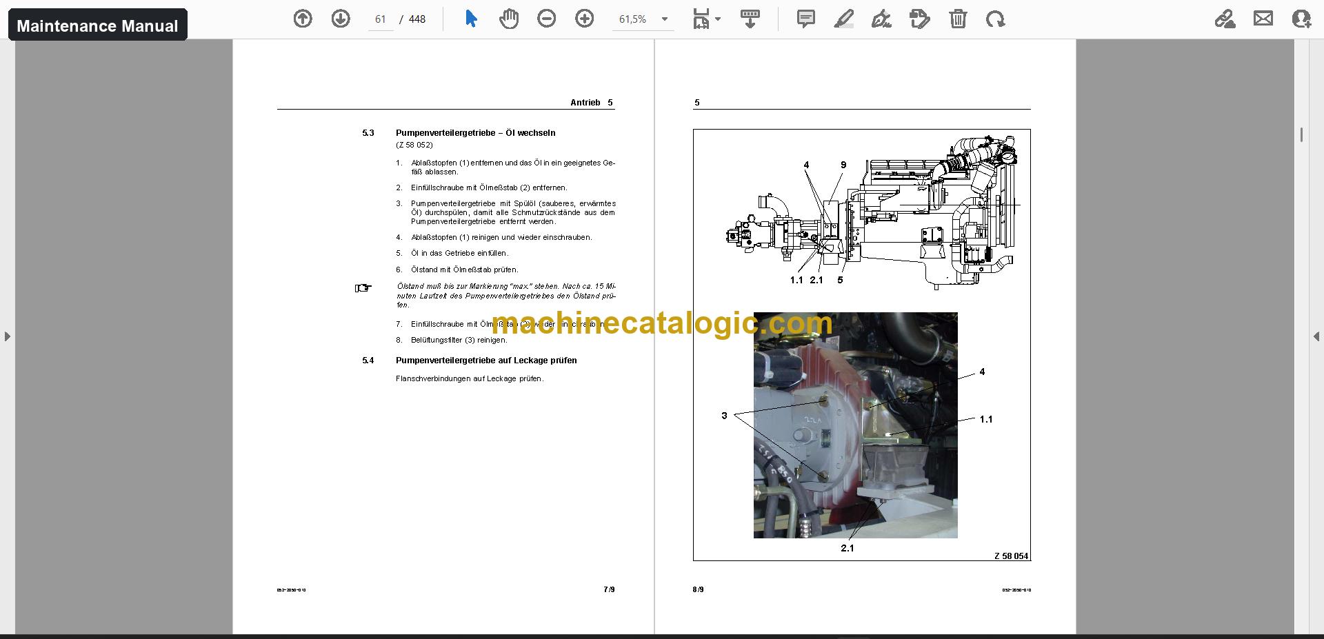
Manuals Included: Operator Manual (2,506 pages), Parts Manual (3,406 pages), Maintenance Manual (1,842 pages), Schematics (111 files), Service information (1 file), Load charts (1,783 files), Technical data (20 files), Training documents (5 files)

Publication No.: Operator Manual: 052-1000-018, 52010en, 52012en; Parts Manual: 52010, 52012.1; Maintenance Manual: 052-2000-018, 52012en, 52012nl

Type of Document: Full Manual Set

Searchable: Partly, some files are scanned pages without a text layer

Delivery: Instant download after payment

Categories: ,

$ 100

Share:

Demag CC 6800 Crawler Crane Full Manual (Operator, Parts, Maintenance, Schematics)

Demag's CC 6800 is a heavy-lift crawler crane that works long projects where big loads have to be set and the crane stays on site for weeks. This full manual set suits a workshop taking on a used crane that came without any paperwork. You get every document for the one model in a single download, so the person at the crane and the person ordering parts work from the same files.

What this manual set helps you do

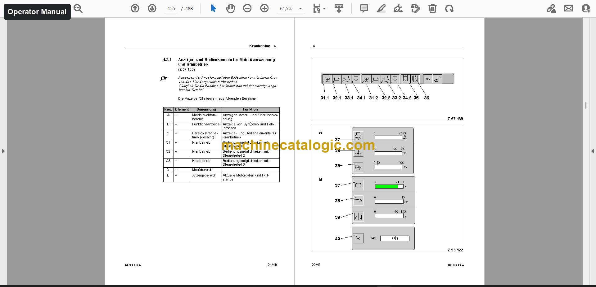
  • Operate the crane from the cab, drive the crawler carrier and slew the superstructure using the Operator Manual.
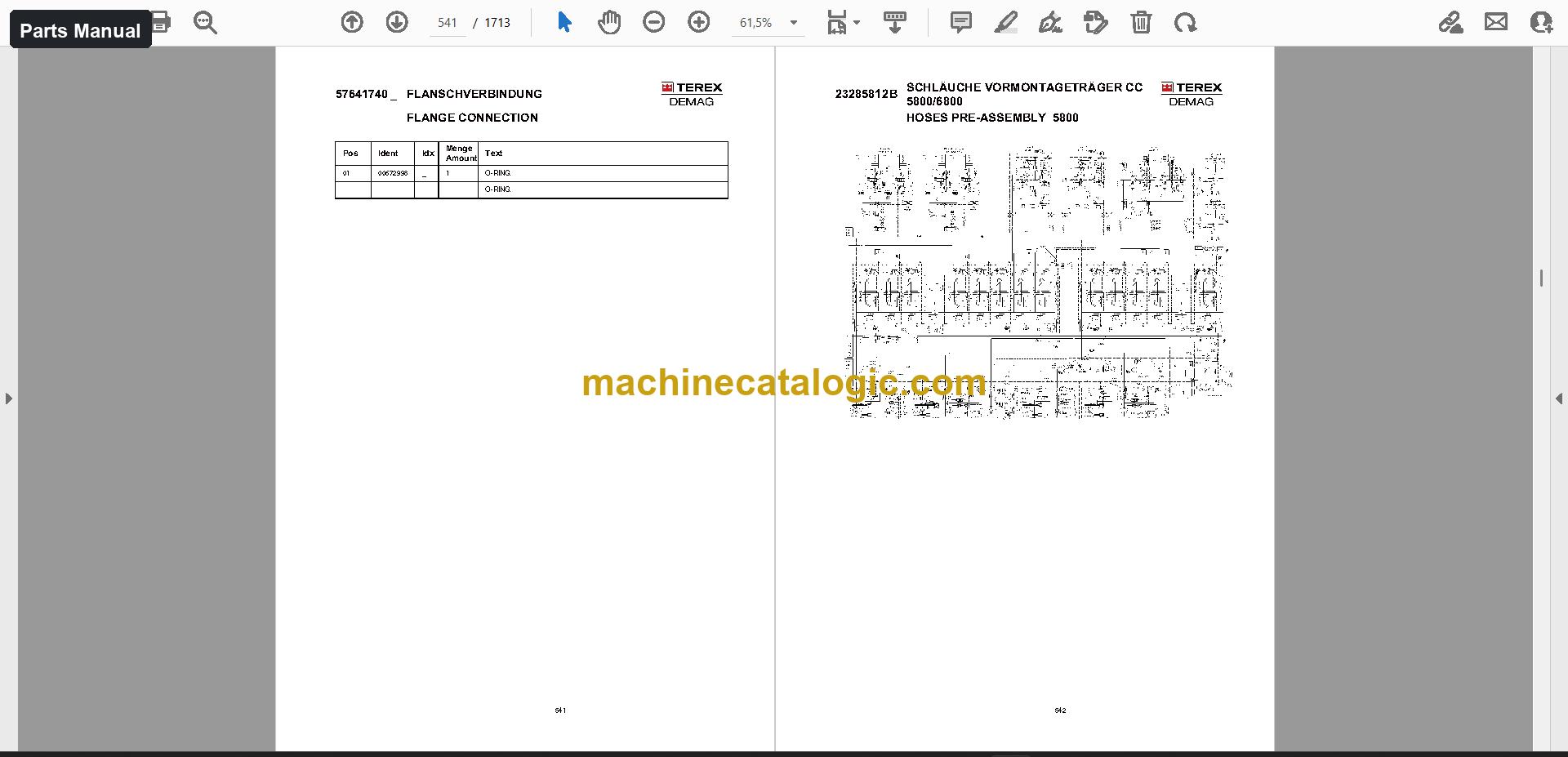
  • Order parts with the Spare Parts Catalogue, which covers groups such as the undercarriage, outrigger cylinder, slew ring, diesel engine and pump.
  • Lubricate and inspect on schedule with the Lubrication and Maintenance Manual, including the slew gear, hoists and roller bearing slewing rim.
  • Trace the hydraulic system and electrical system through the schematics.
  • Plan the job with the load charts and the assembly and installation documents.

Who this is for

A workshop or service company taking over a CC 6800 gets the maintenance schedule, the parts breakdowns and the schematics in one place. A rental fleet manager can hand the operator manual to crews and the parts catalogue to the parts desk without chasing separate books.

FAQ

Q: What do I receive and how is it organised?

A: One download with 2,129 files, 1,843 of them PDF, totalling 144,082 PDF pages. The Operator Manual is 2,506 pages in 5 files, the Parts Manual is 3,406 pages in 2 files, and the Maintenance Manual is 1,842 pages in 4 files. The set is in English, Dutch and German, with the parts catalogue in English and German.

Q: Which machine does it fit?

A: The Demag CC 6800 crawler crane. The titles are CC 6800 Operator Manual, CC 6800 Spare Parts Catalogue and CC 6800 Lubrication and Maintenance Manual.

Q: How does it fit my job?

A: Schematics (111 files, 1,374 pages), technical data, assembly and installation documents (63 files), training documents and the load charts sit alongside the three manuals. Operators, mechanics and the parts desk can all work from the same set.

Put the whole CC 6800 documentation on your workshop computer and keep every crew member working from the same files.

📘 Show Index

Table of Contents:

Operator Manual Table of Contents

2,506 pages, 5 files

  • Publication 052-1000-018 (554 pages)
    • Manufacturer’s specifications
    • Foreword
    • Safety Instructions
      • General
      • Intended Use
      • Operating Conditions and Computed Design of the Crane
    • Description of the Crawler−mounted Crane
      • Overview
      • Superstructure
      • Crawler Chassis
    • Crane Operator’s Cab
      • Controls in the Crane Operator’s Cab
      • Control levers
      • Add−on Console
    • Engine and Drive
      • Engine Control
      • Starting
      • Automotive Driving
    • Driving the Crawler−mounted Crane
      • General
      • Controlling the Undercarriage
      • Driving without Load on the Horizontal and Angled Road Surface
    • Slewing and Braking the Superstructure
      • Speed Control
      • Slewing
      • Braking the Superstructure
  • Publication 52010en (488 pages)

    Same chapters as the edition above (another edition or language of this manual).

  • Publication 52012en (1,464 pages)
    • Manufacturer’s specifications
    • Foreword
    • Safety Instructions
      • General
      • Intended Use
      • Operating Conditions and Computed Design of the Crane
    • More Cranes
      • Hand Signals
      • Power Supply Failure
    • Description of the crawler−mounted crane
      • Overview
      • Superstructure
      • Undercarriage
    • Crane Operator’s Cab
      • Controls in the Crane Operator’s Cab
      • Control lever
      • Add−on console
    • Engine and Drive
      • Engine control
      • Starting
      • Automatic Driving
    • Driving the Crawler−mounted Crane
      • General
      • Controlling the Undercarriage
      • Driving without Load on the Horizontal and Angled Road
    • Surface
      • Driving with Load on a Horizontal and Graded Road
    • Slewing and Braking the Superstructure
      • Speed Control
      • Slewing
      • Braking the Superstructure
    • position
    • Operating the Safety Equipment
      • IC−1 crane control
    • the LMI system”(LMI screen)
    • the Engine and Crane Operating System”(MOT screen)
    • Crane
      • Limit switches
      • Dead man’s handle
    • Working with the Crane Equipment
      • Preparations
      • Selection of the functions for crane operation
      • Configuring the crane equipment
    • in Combined Operation
    • Working with the Superlift
      • Description of the Superlift Equipment
      • Modus operandi
      • Safety instructions for working with the Superlift
    • Operating the Heating and Ventilation
      • Operating the Heating
      • Heating operation
      • Operating the air conditioning system
    • Parking the Crane
      • Wind Speeds
      • Lowering the Boom System
    • Emergency operation
      • Emergency control system with the mobile control panel
    • Radio Remote Control
      • General
      • Preparations for Assembly using the Radio Remote Control
      • Tabular Collation of the Assembly Procedures
    • Failure
      • Virtual radio remote control
      • Manual control of assembly procedures
      • Error diagnosis

Parts Manual Table of Contents

3,406 pages, 2 files

  • Manual 1 (1,713 pages)
    • Undercarriage
    • Cylinder
    • Seal Kit
    • Drive Gear Box
    • Cylinder Head Bolt
    • Brake Assy
    • Control Part
    • Transmission
    • Shaft Seal
    • Connector Plate
    • Brake Valve
    • Track Adjusting Cylinder
    • Track Frame Left Hand Cpl 2000
    • Lube Pump
    • Outrigger Cylinder
    • Guide Ring
    • Support Plate
    • Mounting Cylinder
    • Flap Cylinder
    • Hydraulic Undercarriage
    • Hydraulic Circuit Diagram Carrier Cc 580
    • Solenoid Valve
    • Coupling Sleeve
    • Seat Valve With Housing
    • Hydraulic Circuit Diagram Carrier Cc5800
    • Hoses Crawler Cc 5800
    • Electrical Supply Undercarriage Tc
    • Cable
    • Catwalks Undercarriage
    • Superstructure
    • Mounting Parts
    • Hand Winch
    • Mounting Catwalk
    • Fold-away Step
    • Mirror
    • Slew Ring Arr
    • Slew Ring
    • Mounting Slew Gear
    • Slew Gear
    • Power Unit
    • Pump Displacement
    • Flanged Nut
    • Drive
    • Premounting Drive
    • Diesel Engine
    • Filter Element
    • Coupling To Fan
    • Hydr.pump
    • Governor Unit
    • Carrier, Pump
    • Transmission, Assy
    • Cover Plate, Assy
    • Pressure Relief Valve
    • Shut Down Valve
    • NUT
    • O-ring
    • Gear Pump Kit
    • Gear Pump
    • Modulation Control, Assy
    • Filter System
    • Filter Assy
    • Filter Head
    • Hydr. Pump, Assy
    • Carrier Pump
    • Shuttle Valve
    • Control Valve
    • Pump Distributor Gear
    • Pre-assembly Drive
    • Hydr. Pump
    • H-system Support Pre-assembly Cc 5800
    • Control Block
    • Pressure Valve
    • Directional Spool Valve
    • Valve
    • Pressure Reducing Valve
    • Remote Control Manifolds
    • Hoses Pre-assembly 5800
    • Mounting Oil Cooler
    • Oil Cooler
    • Pre-assembly Cooling System
    • Suction Lines
    • Fuel System
    • Fuel-water Separator
    • Pre-assembly Fuel-tank
    • Pre-mounting Hydraulic Tank
    • Hydraulic Tank
    • Return Oil Filter
    • Cover (for Cleaning)
    • Hoses Piping Engine Frame Cc 5800
    • Mounting Tank
    • Expansion Tank
    • Electric Cooling Water
    • Mounting Engine Covering
    • Pump Covering
    • Engine Covering
    • Exhaust System
    • Air Filter Mounting
    • Air Suction Adapter
    • Air Filter
    • Reeving Winch Mounting
    • Reeving Winch
    • Winch Gear
    • Seal Ring
    • Brake Modifications Kit 11 Chassis 06
    • Cab Superstructure 1200, Cpl
    • CAB
    • Cabin Superstructure 1200 Aurora
    • Pump
    • Electric Cab
    • Wiper Roof
    • Rotaflare Light
    • Heater Cpl
    • Heater
    • Metering Pump
    • Water Pump
    • Hose Clip
    • Fuel Filter
    • Harness
    • Exhaust Hose
    • Air Conditioning Unit
    • Covering Parts, Cab 1200
    • Seat
    • Immersion Heater Rear
    • Immersion Heater Seat
    • Seat Support
    • Platform With Railing For Cabine
    • Cotter Pin
    • Air Condition Arr
    • Air Conditioning Equipment
    • Hydraulic
    • Hydr. System
    • Hydraulic Add. Parts Cc 5800
    • Hoses Add. Parts Cc 5800
    • Hydraulic Luffing Gear 1 Superstructure
    • Hoses Luffing Gear 1 Superstructure Cc 5
    • Hydraulic Luffing Gear 2 Superstructure
    • Hoses Luffing Gear 2 Superstructure Cc 5
    • Hydraulic Hoist Gear 3 Superstructure Cc
    • Hoses Hoist Gear 3 Superstructure Cc 580
    • Electric
    • Electric Superstructure
    • Electrical Superstructure
    • Electric Pressure Transducer
    • Socket Box
    • Fuse Box
    • Switch
    • Push-toggle Switch
    • Lamp
    • Electric Leteral Console Installation Ca
    • Circuit Plate
    • Coupling Relais
    • Electric Seat Driver
    • Pilot Control Lever
    • Electric Air Conditioning Equipment
    • Mounting Parts Hoist Gear 1
    • Electrical Hoist Gear 1
    • Slip Ring
    • Mounting Parts Hoist Gear 2
    • Electrical Hoist Gear 2
    • Mounting Parts Derricking Gear
    • Electrical Derricking Gear
    • Mounting Parts A-frame
    • Electrical A-frame
    • Remote Control
    • Emergency Control System Remote
    • Mounting Parts Electrical Superstr
    • Electric External Start
    • Safety Decals Ce
    • UNTERWAGEN / UNDERCARRIAGE
  • Publication 52012.1 (1,693 pages)

    Same chapters as the edition above (another edition or language of this manual).

Maintenance Manual Table of Contents

1,842 pages, 4 files

  • Publication 052-2000-018 (498 pages)
    • Foreword
    • Safety Instructions
    • Oils, Lubricants and Capacities
    • Lubrication and Maintenance Schedule
    • Drive
    • Roller Bearing Slewing Rim
    • Slew Gear
    • Hoists
    • Luffing Gears
    • Derricking gear
    • Equipment
    • Hydraulic System
    • Heating and Air conditioning
    • Electrical System
    • Fuel System
    • Cooling, Intake and Exhaust System
    • Piston Rods
    • Crane Operator’s Cab
    • Undercarriage
    • Counterweight Dolly
    • Visual checks
    • Examinations of the Crane
    • Central Lubrication System
  • Publication 52012en (1,344 pages)
    • Foreword
    • Safety Instructions
    • Oils, lubricants and capacities
    • Lubrication and Maintenance Schedule
    • Drive
    • Connections
    • Roller bearing slewing rim
    • hydraulic cylinder
    • slew gear
    • Hoists
    • Bearings
    • the Screw Connections if Necessary
    • Luffing Gears
    • Re−tightening if Necessary
    • derricking gear
    • Equipment
    • and Equipment
    • Hydraulic System
    • element
    • Checking the Flexible Pressure Tubing
    • Replacing the Flexible Pressure Tubing
    • Checking the Accumulator Initial Gas Pressure
    • Checking the Oil Level
    • outrigger cylinder
    • Heating and Air conditioning
    • Electrical System
    • on the Rotary Joint to the Undercarriage
    • Fuel System
    • Cooling, intake and exhaust system
    • Piston Rods
    • Crane Operator’s Cab
    • Assembly
    • Undercarriage
    • and Checking the Track Tension in the Case of Running Noises
    • Necessary
    • Visual checks
    • frame
    • Examinations of the Crane

Also in this set

  • Schematics (111 files, 1,374 pages)
  • Load charts (1,783 files, 122,380 pages)
  • Technical data (20 files, 170 pages)
  • Service information (1 file, 1 pages)
  • Assembly and installation (63 files, 4,496 pages)
  • Training documents (5 files, 7,907 pages)
  • Other documents (135 files)

Demag PDF Manuals

All Crane Manuals

Related Manuals

0
0
Your Cart
Your cart is emptyReturn to Shop