$ 0
0
$ 0
0

Detroit Diesel 16 V 4000 E20 Workshop Manual

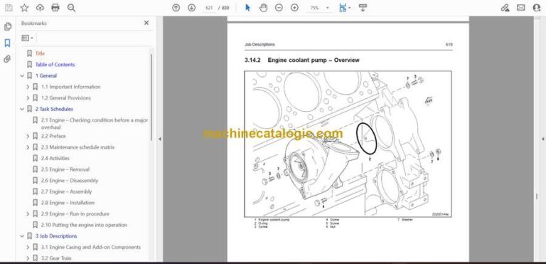
Format: PDF (Printable Document)

File Language: English

File Pages: 830

File Size: 100.69 MB (Speed Download Link)

Brand: Detroit Diesel

Model: 16 V 4000 E20

Type of Document: Workshop Manual

Category:

$ 45

Share:

Detroit Diesel 16 V 4000 E20 Workshop Manual

Detroit Diesel 16 V 4000 E20 Workshop Manual

📘 Show Index

Detroit Diesel 16 V 4000 E20 Index:

  • Title
  • Table of Contents
  • 1 General
    • 1.1 Important Information
      • 1.1.1 Reman assemblies – Prerequisites for maintenance tasks and general assembly instructions
        • REMAN assemblies
        • The following assemblies are only available through the exchange procedure
        • Requirements for maintenance tasks
        • General assembly instructions
        • Information on installation of Flexmaster pipe connection
    • 1.2 General Provisions
      • 1.2.1 General Instructions
        • General
        • Correct use
        • Modifications or conversions
        • Spare parts
        • Reworking components
      • 1.2.2 Personnel and organizational requirements
        • Personnel requirements
        • Organizational measures
        • Working clothes and protective equipment
      • 1.2.3 Safety precautions when working on the engine
        • Safety precautions when putting the equipment into operation
        • Safety requirements for operators
        • Engine operation
        • Maintenance and repair
        • Welding work
        • Hydraulic installation and removal
        • Working on electrical/electronic assemblies
        • Working with laser equipment
        • Operation of electrical equipment
      • 1.2.4 Auxiliary materials, fire prevention and environmental protection
        • Fire prevention
        • Noise
        • Environmental protection
        • Auxiliary materials
        • Lead
        • Acids and alkaline solutions
        • Painting
        • Liquid nitrogen
        • Compressed air
        • Used oil
      • 1.2.5 Standards for warning notices in the publication
      • 1.2.6 General information regarding the Tolerances and Wear Limits List
        • The tolerances and wear limits are intended as a guide for the examination of engine componentsas well as for engine inspection and repair.
      • 1.2.7 Engine side and cylinder designations
      • 1.2.8 Torque specifications for screws, nuts and bolts
        • Crankcase
        • Crank drive
        • Cylinder head
        • Valve gear
        • Fuel system – High-pressure
        • Exhaust turbocharger
        • Exhaust pipework
        • Starter
        • Lube oil system
        • Battery-charging generator
        • Auxiliary PTO
        • Monitoring, control and regulation devices
        • Tightening torques for setscrew and stud connections to works standard MTN 5008
        • When tightening mechanically, the permitted assembly tolerance is +15 %.
        • Tightening torques for stress bolt connections prescribed in standard MTN 5007
        • Tightening torques for plug screws as per MTN 5183-1 standard
        • Tightening torques for plug screws as per DIN 7604C (with long screwed plug)
        • Tightening torques for banjo screws as per MTN 5183-2 standard
        • Tightening torques for banjo screws made of steel
        • Tightening torques for banjo screws made of copper/aluminum alloys
        • Tightening torques for male connector as per MTN 5183-3 standard
        • Tightening torques for union nuts on screwed plugs ISO 6149-3
      • 1.2.9 Settings
        • Firing order for Series 4000 engines
        • Direction of rotation, viewed towards driving end
        • Valve clearance, engine cold (20 °C)
        • Valve timing with valve clearance adjusted
        • Cam and valve lift for camshaft adjustment
      • 1.2.10 Conversion tables
        • Length
        • Area
        • Volume
        • Speed
        • Mass
        • Force
        • Density
        • Torque
        • Pressure
        • Mass moment, 2nd grade
        • Energy
        • Power
        • Temperature
        • Fuel consumption
      • 1.2.11 Repairing threaded bores with threaded inserts (Heli-Coil)
      • 1.2.12 Abbreviations
  • 2 Task Schedules
    • 2.1 Engine – Checking condition before a major overhaul
    • 2.2 Preface
      • MTU maintenance concept
      • Notes on maintenance
      • Out-of-service periods
      • Application group
      • Load profile
      • Load profile table
    • 2.3 Maintenance schedule matrix
      • 0-10,500 Operating hours
      • 11,000-15,000 Operating hours
    • 2.4 Activities
    • 2.5 Engine – Removal
    • 2.6 Engine – Disassembly
    • 2.7 Engine – Assembly
    • 2.8 Engine – Installation
    • 2.9 Engine – Run-in procedure
      • Running in engine after replacing parts
      • Adjust engine operational data
    • 2.10 Putting the engine into operation
  • 3 Job Descriptions
    • 3.1 Engine Casing and Add-on Components
      • 3.1.1 Engine layout
        • Illustration applies analogously to 8/12/16 V 4000 G, C and R
      • 3.1.2 Crankcase and attachments – Overview
        • Crankcase and attachments – Overview
      • 3.1.3 Crankcase – Overview
        • Crankcase with cover
        • Crankcase
        • Inspection port cover
        • Oil dipstick with guide tube
        • Oil filler neck
      • 3.1.4 Crankcase – Disassembly
      • 3.1.5 Crankcase – Cleaning
      • 3.1.6 Crankcase – Check
      • 3.1.7 Crankcase – Tolerances
        • Crankcase bore for crankshaft
        • Crankcase bore for camshaft
        • Crankcase bore for cylinder liner
        • Crankshaft bearing cap
        • Main bearing bore
        • Crankcase crankshaft bore coaxiality
        • Crankcase camshaft bore coaxiality
      • 3.1.8 Crankcase – Assembly
      • 3.1.9 Cylinder liner – Overview
        • Overview of cylinder liner with scraper ring
        • Cylinder liner with scraper ring in crankcase
      • 3.1.10 Cylinder liner – Removal
      • 3.1.11 Cylinder liner – Cleaning
      • 3.1.12 Cylinder liner – Check
      • 3.1.13 Cylinder liners – Tolerances
        • Reconditioning instructions:
      • 3.1.14 Cylinder liner – Installation
      • 3.1.15 Oil pan – Overview
        • Oil pan (shallow and deep version)
        • Oil pan with suction basket
        • View from free end
      • 3.1.16 Oil pan – Removal
      • 3.1.17 Oil pan – Cleaning
      • 3.1.18 Oil pan – Check
      • 3.1.19 Oil pan – Installation
      • 3.1.20 Oil pan – Tightening sequence for oil pans made of aluminium billet and aluminium castings
        • All applications with 4 engine mounting brackets
        • All applications with 2 engine mounting brackets or without engine mounting brackets
        • Oil pan screw joints
      • 3.1.21 Engine lifting equipment – Overview
        • Overview
        • Engine lifting equipment
      • 3.1.22 Engine lifting equipment – Removal
      • 3.1.23 Engine lifting equipment – Cleaning
      • 3.1.24 Engine lifting equipment – Check
      • 3.1.25 Engine suspension – Installation
      • 3.1.26 End housing driving end – Overview
        • End housing with externally mounted components
        • Guide bushing arrangement for end housing installation and removal
      • 3.1.27 End housing, driving end – Removal
      • 3.1.28 End housing, driving end – Dismantling
      • 3.1.29 End housing, driving end – Cleaning
      • 3.1.30 End housing, driving end – Check
      • 3.1.31 End housing driving end – Tolerances
      • 3.1.32 End housing, driving end – Assembly
      • 3.1.33 End housing, driving end – Installation
      • 3.1.34 Crankcase ventilation – Overview
        • Crankcase ventilation, free end, variant A
        • Crankcase ventilation, driving end, variant A
        • Crankcase ventilation variant B
      • 3.1.35 Crankcase ventilation – Removal
      • 3.1.36 Crankcase breather – Cleaning
      • 3.1.37 Oil separator – Check
      • 3.1.38 Oil separator – Disassembly
      • 3.1.39 Oil separator – Assembly
      • 3.1.40 Crankcase ventilation – Installation
    • 3.2 Gear Train
      • 3.2.1 Gearcase, free end – Overview
        • Arrangement of alignment tool for equipment carrier and equipment carrier cover
      • 3.2.2 Gearcase, free end – Removal
      • 3.2.3 Gearcase, free end – Disassembly
      • 3.2.4 Gearcase, free end – Cleaning
      • 3.2.5 Gearcase, free end – Check
      • 3.2.6 Gearcase, free end – Tolerances
        • Crankshaft bearing, free end, 8/12/16V
        • Crankshaft bearing, free end, 20V
      • 3.2.7 Gearcase, free end – Assembly
      • 3.2.8 Gearcase, free end – Installation
      • 3.2.9 Gear train, free end – Overview
        • 3.2.10 Gear train, free end – Removal
      • 3.2.11 Gear train, free end – Cleaning
      • 3.2.12 Gear train, free end – Check
      • 3.2.13 Gear train, free end – Tolerances
      • 3.2.14 Gear train, free end – Installation
      • 3.2.15 Bearing bush – Removal and installation
    • 3.3 Crank Drive
      • 3.3.1 Running gear – Overview
        • Running gear
      • 3.3.2 Crankshaft overview
        • Crankshaft, detail
        • Crankshaft
        • Crankshaft with bearing
      • 3.3.3 Crankshaft – Removal
      • 3.3.4 Crankshaft – Disassembly
      • 3.3.5 Crankshaft – Cleaning
      • 3.3.6 Crankshaft – Check
      • 3.3.7 Crankshaft – Tolerances
        • Crankshaft bearing shell
        • Conrod bearings
        • Crankshaft bearing – expansion dimension
        • Crankshaft axial play
        • Crankshaft bearing shells
        • Crankshaft gear, free end
        • Main bearing journal concentricity
      • 3.3.8 Crankshaft – Assembly
      • 3.3.9 Crankshaft – Balancing
      • 3.3.10 Main bearing shells – Check
        • Checking main bearing shells
        • Main bearing shells (grooved bearing), upper half
        • Assessment
        • Main bearing shell (sputtered bearing), lower half
        • Assessment
        • Damage to bearing
      • 3.3.11 Main bearing bore – Check
      • 3.3.12 Crankshaft – Installation
      • 3.3.13 PTO flange, driving end, flywheel – Overview
        • Layout for installation/removal jig for flywheel
      • 3.3.14 PTO flange, driving end, flywheel – Removal
      • 3.3.15 Radial-lip shaft seal, driving end – Removal
      • 3.3.16 PTO flange, driving end, flywheel – Cleaning
      • 3.3.17 PTO flange, driving end – Flywheel check
      • 3.3.18 Radial-lip shaft seal, driving end – Installation
      • 3.3.19 PTO flange, driving end, flywheel – Installation
      • 3.3.20 Crankshaft PTO, free end – Overview
        • Arrangement of drive flange installation/removal tool
      • 3.3.21 Vibration damper on PTO, free end – Removal
      • 3.3.22 Vibration damper on PTO, free end – Disassembly
        • Vibration damper – Disassembly
      • 3.3.23 Vibration damper on PTO, free end – Cleaning
      • 3.3.24 Vibration damper on PTO, free end – Check
      • 3.3.25 Vibration damper on PTO, free end – Tolerances
      • 3.3.26 Vibration damper on PTO, free end – Installation
      • 3.3.27 Pistons and conrods – Overview
        • Pistons and conrods
        • Piston details
      • 3.3.28 Piston and conrod – Removal
      • 3.3.29 Piston and conrod – Disassembly
      • 3.3.30 Piston – Cleaning
      • 3.3.31 Piston – Check
      • 3.3.32 Piston – Tolerances
        • Piston bearing
        • Piston rings
        • Piston clearance in cylinder liner
        • Piston crown mounting
      • 3.3.33 Conrod – Disassembly
      • 3.3.34 Conrod – Cleaning
      • 3.3.35 Conrod – Check
      • 3.3.36 Conrod – Tolerances
        • Conrod bearings
        • Conrod bearing, locating pin
        • Conrod screw length
        • Conrod bore parallelism
        • Small conrod bore
      • 3.3.37 Conrod – Assembly
      • 3.3.38 Conrod bearing shell – Assessment
        • Lower conrod bearing shell (grooved bearing) – Assessment
        • Assessment
        • Damage to bearing
        • Upper conrod bearing half shell (sputtered bearing) – Assessme
        • Assessment
      • 3.3.39 Piston – Assembly
      • 3.3.40 Piston and conrod – Installation
    • 3.4 Cylinder Head
      • 3.4.1 Cylinder head and attachments – Overview
        • Overview of cylinder head and attachments
      • 3.4.2 Valve-seat turning machine for cylinder head
        • Working principle of valve-seat turning machine
        • Installing the solid pilot
        • Mounting the supporting spider
        • Inserting the pilot into the valve guide
        • Locking the pilot
        • Setting up valve turning machine
        • Mounting the cutter
        • Placing the valve-turning machine on the pilot
        • Aligning the cutting edge with the valve-seat center
        • Connecting the machine to power supply
        • Valve seat turning
        • Positioning the cutter at the inner valve-seat edge
        • Setting cutting depth
        • Lubricating the valve seat
        • Valve seat turning
        • Repeating the cutting pass
        • Replacing the adapter head
        • Removing the adapter head
        • Mounting the adapter head
      • 3.4.3 Cylinder head – Removal
      • 3.4.4 Cylinder head – Disassembly
      • 3.4.5 Cylinder head – Cleaning
      • 3.4.6 Cylinder head – Check
      • 3.4.7 Cylinder head – Tolerances
        • Inlet and exhaust valve guides
        • Valve clearance
        • Inlet and exhaust valve seat ring
        • Exhaust valve seat
        • Inlet valve seat
        • Inlet valve elliptical chamfer
        • Exhaust valve
        • Inlet valve
        • Valve springs, exterior
        • Valve springs, interior
        • Cylinder head – Mating surface – Protective sleeve – Valve bridge
        • Cylinder head screws
      • 3.4.8 Cylinder head – Repair
      • 3.4.9 Cylinder head – Assembly
      • 3.4.10 Cylinder head – Installation
      • 3.4.11 Cylinder head – Plug repair
    • 3.5 Valve Gear
      • 3.5.1 Valve gear – Overview
        • Valve gear – Overview
      • 3.5.2 Camshaft overview
        • Overview of camshaft
      • 3.5.3 Camshaft – Removal
      • 3.5.4 Camshaft – Cleaning
      • 3.5.5 Camshaft running surfaces and swing followers – Visual check
      • 3.5.6 Camshaft – Check
      • 3.5.7 Camshaft – Tolerances
        • Concentricity of bearings
        • Axial play
      • 3.5.8 Camshaft – Installation
      • 3.5.9 Camshaft drive – Overview
        • Camshaft drive – Overview
      • 3.5.10 Camshaft drive – Removal
      • 3.5.11 Camshaft drive – Cleaning
      • 3.5.12 Camshaft drive – Check
      • 3.5.13 Camshaft drive – Installation
      • 3.5.14 Camshaft thrust bearing – Overview
        • Overview of camshaft thrust bearing
      • 3.5.15 Camshaft thrust bearing – Replacement
      • 3.5.16 Camshaft thrust bearing – Cleaning
      • 3.5.17 Camshaft thrust bearing – Check
      • 3.5.18 Valve drive – Overview
        • Swing follower, swing follower assembly
        • Rocker shaft support
        • Swing follower
        • Valve bridge
      • 3.5.19 Valve drive – Removal
      • 3.5.20 Valve drive – Disassembly
      • 3.5.21 Valve drive – Cleaning
      • 3.5.22 Valve drive – Check
      • 3.5.23 Valve drive – Tolerances
        • Rocker shaft support, inlet and exhaust
        • Swing follower support, inlet and exhaust
      • 3.5.24 Valve drive – Assembly
      • 3.5.25 Valve drive – Installation
      • 3.5.26 Valve drive – Removal
      • 3.5.27 Valve drive – Disassembly
      • 3.5.28 Valve drive – Cleaning
      • 3.5.30 Valve drive – Tolerances
        • Rocker shaft support, inlet and exhaust
        • Swing follower support, inlet and exhaust
      • 3.5.31 Valve drive – Assembly
      • 3.5.32 Valve drive – Installation
      • 3.5.33 Cylinder head cover – Overview
        • Overview of cylinder head cover
      • 3.5.34 Cylinder head cover – Removal
      • 3.5.35 Cylinder head cover – Cleaning
      • 3.5.36 Cylinder head cover – Check
      • 3.5.37 Cylinder head cover – Installation
    • 3.6 Fuel System – High-Pressure
      • 3.6.1 H.P. fuel system – overview
        • H.P. fuel system – overview
      • 3.6.2 H.P. pump – Overview
        • Front view of H.P. pump
      • 3.6.3 H.P. pump – Removal
      • 3.6.4 High-pressure pump – Disassembly
      • 3.6.5 H.P. pump – Check
      • 3.6.6 H.P. pump – Installation
      • 3.6.7 H.P. fuel pump – Control block replacement
      • 3.6.8 Fuel injector – overview
        • Fuel injector – overview
      • 3.6.9 Fuel injector – Removal
      • 3.6.10 Fuel injector disassembly
      • 3.6.11 Fuel injector cleaning
      • 3.6.12 Fuel injector inspection
      • 3.6.13 Fuel injector – Installation
      • 3.6.14 H.P. fuel line – Overview
        • H.P. line from H.P. accumulator to injector
        • H.P. line from H.P. fuel pump to H.P. accumulator
        • H.P. accumulator and attachments
        • H.P. accumulator, left engine side
        • H.P. accumulator, right engine side
      • 3.6.15 HP fuel line – Removal
      • 3.6.16 HP fuel line – Disassembly
      • 3.6.17 H.P. fuel line – Cleaning
      • 3.6.18 H.P. fuel line – Check
      • 3.6.19 HP fuel line – Assembly
      • 3.6.20 H.P. fuel line – Installation
      • 3.6.21 H.P. fuel system – Leak check
    • 3.7 Fuel System – Low-Pressure
      • 3.7.1 Low pressure fuel system – Overview
      • 3.7.2 Fuel delivery pump – Removal
      • 3.7.3 Fuel delivery pump – Disassembly
        • Disassembling fuel delivery pump
      • 3.7.4 Fuel delivery pump – Cleaning
      • 3.7.5 Fuel delivery pump – Check
      • 3.7.6 Fuel delivery pump – Installation
      • 3.7.7 Fuel lines from delivery pump to filter – Overview
      • 3.7.8 Fuel lines from pump to filter – Removal
      • 3.7.9 Fuel lines from pump to filter – Cleaning
      • 3.7.10 Fuel lines from pump to filter – Check
      • 3.7.11 Fuel lines from delivery pump to filter – Installation
      • 3.7.12 Fuel duplex filter – Overview
      • 3.7.13 Fuel duplex filter – Removal
      • 3.7.14 Fuel duplex filter – Disassembly
      • 3.7.15 Fuel duplex filter – Cleaning
      • 3.7.16 Fuel duplex filter – Check
      • 3.7.17 Fuel duplex filter – Assembly
      • 3.7.18 Fuel duplex filter – Installation
      • 3.7.19 Fuel lines from fuel filter to HP pump – Overview
      • 3.7.20 Fuel supply pipework from fuel filter to H.P. pump – Removal
      • 3.7.21 Fuel supply pipework from fuel filter to H.P. pump – Cleaning
      • 3.7.22 Fuel supply pipework from fuel filter to H.P. pump – Check
      • 3.7.23 Fuel supply pipework from fuel filter to H.P. pump – Installation
      • 3.7.24 Leak-off fuel line – Overview
      • 3.7.25 Leak-off fuel line – Removal
      • 3.7.26 Leak-off fuel line – Cleaning
      • 3.7.27 Leak-off fuel line – Check
      • 3.7.28 Leak-off fuel line – Installation
    • 3.8 Exhaust Turbocharger
      • 3.8.1 Exhaust turbochargers
        • Illustration applies analogously to 12V / 16V 4000 G
      • 3.8.2 Exhaust turbocharger – Overview
      • 3.8.3 Exhaust turbocharger – Removal
      • 3.8.4 Exhaust turbocharger – Disassembly
      • 3.8.5 Exhaust turbochargers – Cleaning
      • 3.8.6 Exhaust turbocharger – Check
      • 3.8.7 Exhaust turbocharger – Assembly
      • 3.8.8 Exhaust turbochargers – Installation
    • 3.9 Charge-Air Cooling
      • 3.9.1 Charge-air cooling – Overview
        • Intercooler and attachments
      • 3.9.2 Intercooler – Removal
      • 3.9.3 Intercooler – Disassembly
        • Intercooler – Disassembly
      • 3.9.4 Intercooler – Cleaning
        • Air-side cleaning
        • Water-side cleaning
        • Intercooler flushing
        • Intercooler drying and preservation
      • 3.9.5 Intercooler – Check
      • 3.9.6 Charge-air cooler – Installation
    • 3.10 Air Intake/Air Supply
      • 3.10.1 Air intake / air supply – Overview
      • 3.10.2 Intake air system to cylinders, left – Overview
      • 3.10.3 Air supply system to cylinders, left – Removal
      • 3.10.4 Air supply system to cylinders, left – Cleaning
      • 3.10.5 Air supply system to cylinders, left – Check
      • 3.10.6 Air supply system to cylinders, left – Installation
      • 3.10.7 Air supply system to cylinders, right – Overview
      • 3.10.8 Air supply system to cylinders, right – Removal
      • 3.10.9 Air supply system to cylinders, right – Cleaning
      • 3.10.10 Air supply system to cylinders, right – Check
      • 3.10.11 Air supply system to cylinders, right – Installation
      • 3.10.12 Air ducts from turbochargers to intercooler – Overview
        • Air supply, variant A
        • Illustration applies analogously to 8/12/16 V 4000 G
        • Air supply, variant B
        • Illustration applies analogously to 8/12/16 V 4000 G
      • 3.10.13 Air ducts from exhaust turbochargers to intercooler – Removal
      • 3.10.14 Air ducts from turbochargers to intercooler – Cleaning
      • 3.10.15 Air ducts from turbochargers to intercooler – Check
      • 3.10.16 Air ducts from turbochargers to intercooler – Installation
    • 3.11 Exhaust Pipework
      • 3.11.1 Exhaust system – Overview
        • Illustration applies analogously to 8/12/16 V 4000 G
      • 3.11.2 Exhaust pipework after cylinder head – Overview
        • Exhaust pipework, 12 V plug connection – Overview
        • Exhaust pipework, 12 V screwed joint – Overview
        • Exhaust pipework, 16 V – Overview
      • 3.11.3 Exhaust pipework after cylinder head – Removal
      • 3.11.4 Exhaust pipework after cylinder head – Cleaning
      • 3.11.5 Exhaust pipework after cylinder head – Check
      • 3.11.6 Exhaust pipework after cylinder head – Installation
    • 3.12 Starter
      • 3.12.1 Electric starter – Overview
      • 3.12.2 Starter – Removal
      • 3.12.3 Starter – Disassembly
        • Remove starter (→ Page 550).
        • Starter – Disassembly
        • See separate publication No. M060715.
      • 3.12.4 Starter – Cleaning
      • 3.12.5 Starter – Inspection
      • 3.12.6 Starter – Installation
    • 3.13 Lube Oil System, Lube Oil Circuit
      • 3.13.1 Lube oil pump with drive – Overview
      • 3.13.2 Lube oil pump with drive – Removal
      • 3.13.3 Lube oil pump with drive – Disassembly
        • Remove lube oil pump with drive (→ Page 557).
      • 3.13.4 Lube oil pump with drive – Cleaning
      • 3.13.5 Lube oil pump with drive – Check
      • 3.13.6 Lube oil pump with drive – Installation
      • 3.13.7 Oil filter – Overview
        • Oil filter assembly
      • 3.13.8 Oil filter with oil filter housing – Removal
      • 3.13.9 Oil filter housing – Disassembly
      • 3.13.10 Oil filter housing – Cleaning
      • 3.13.11 Oil filter housing – Check
      • 3.13.12 Oil filter housing – Assembly
      • 3.13.13 Oil filter with oil filter housing – Installation
      • 3.13.14 Centrifugal oil filter– Overview
        • Centrifugal oil filter with attachments
        • Centrifugal oil filter with flange
        • Centrifugal oil filter assembly
      • 3.13.15 Centrifugal oil filter – Removal
      • 3.13.16 Centrifugal oil filter – Disassembly
      • 3.13.17 Centrifugal oil filter – Cleaning
      • 3.13.18 Centrifugal oil filter – Check
      • 3.13.19 Centrifugal oil filter – Bearing clearance check
      • 3.13.20 Centrifugal oil filter – Assembly
      • 3.13.21 Centrifugal oil filter – Installation
      • 3.13.22 Oil cooler – Overview
        • Oil cooler with attachments
      • 3.13.23 Oil cooler – Removal
      • 3.13.24 Oil cooler – Cleaning
      • 3.13.25 Oil cooler – Check
      • 3.13.26 Oil cooler – Installation
      • 3.13.27 Oil system in crankcase – Overview
        • Oil system
      • 3.13.28 Oil system in crankcase – Removal
      • 3.13.29 Oil system in crankcase – Cleaning
      • 3.13.30 Oil system in crankcase – Check
      • 3.13.31 Oil system in crankcase – Installation
      • 3.13.32 Turbocharger oil supply – Overview
        • Exhaust turbocharger oil supply
      • 3.13.33 Turbocharger oil supply – Removal
      • 3.13.34 Turbocharger oil supply – Cleaning
      • 3.13.35 Turbocharger oil supply – Check
      • 3.13.36 Turbocharger oil supply system – Installation
    • 3.14 Engine Coolant System
      • 3.14.1 Coolant system – Overview
        • Engine coolant circuit
        • (applicable to 8/12/16 V 4000 Gx1)
      • 3.14.2 Engine coolant pump – Overview
      • 3.14.3 Engine coolant pump – Removal
      • 3.14.4 Engine coolant pump – Disassembly
      • 3.14.5 Engine coolant pump – Cleaning
      • 3.14.6 Engine coolant pump – Check
      • 3.14.7 Engine coolant pump – Tolerances
      • 3.14.8 Engine coolant pump – Assembly
      • 3.14.9 Engine coolant pump – Installation
      • 3.14.10 Coolant supply for engine coolant pump, intake side – Overview
        • Overview drawing
      • 3.14.11 Coolant supply for engine coolant pump, intake side – Removal
      • 3.14.12 Coolant supply for engine coolant pump, intake side – Removal
      • 3.14.13 Coolant supply for engine coolant pump, intake side – Check
      • 3.14.14 Coolant supply for engine coolant pump, intake side – Installation
      • 3.14.15 Coolant pipework after cylinder – Overview
        • Coolant pipework after cylinder – Overview
        • Also applies analogously to 12 V.
      • 3.14.16 Coolant pipework after cylinder – Removal
      • 3.14.17 Coolant pipework after cylinder – Cleaning
      • 3.14.18 Coolant pipework after cylinder – Check
      • 3.14.19 Coolant pipework after cylinder – Installation
      • 3.14.20 Engine coolant and charge air coolant ventilation – Overview
        • Coolant vent lines
        • Applies analogously to 8/12/16 V 4000 G
      • 3.14.21 Engine coolant ventilation and charge-air cooling – Removal
      • 3.14.22 Engine coolant ventilation and charge air cooling – Cleaning
      • 3.14.23 Engine coolant and charge air coolant ventilation – Check
      • 3.14.24 Engine coolant ventilation and charge air cooling – Installation
      • 3.14.25 Charge-air coolant pump – Overview
        • Charge-air coolant pump – Overview
      • 3.14.26 Charge-air coolant pump – Removal
      • 3.14.27 Charge-air coolant pump – Disassembly
      • 3.14.28 Charge-air coolant pump – Cleaning
      • 3.14.29 Charge-air coolant pump – Check
      • 3.14.30 Charge-air coolant pump – Tolerances
      • 3.14.31 Charge-air coolant pump – Assembly
      • 3.14.32 Charge-air coolant pump – Installation
      • 3.14.33 Coolant pipework from/to intercooler – Overview
        • Coolant pipework
      • 3.14.34 Coolant pipework from/to intercooler – Removal
      • 3.14.35 Coolant pipework from/to intercooler – Cleaning
      • 3.14.36 Coolant pipework from/to intercooler – Check
      • 3.14.37 Coolant pipework from/to intercooler – Installation
      • 3.14.38 Coolant pipework with thermostat — Overview
        • Coolant pipework with thermostat
      • 3.14.39 Coolant pipework with thermostat – Removal
      • 3.14.40 Coolant pipework with thermostat – Cleaning
      • 3.14.41 Coolant pipework with thermostat – Check
      • 3.14.42 Coolant pipework with thermostat – Installation
    • 3.15 Power Supply – Engine Side
      • 3.15.1 Battery-charging generator — Overview
        • Overview battery-charging generator with drive (version A)
        • Overview battery-charging generator with drive (version B)
        • Generator drive
      • 3.15.2 Battery-charging generator – Removal
      • 3.15.3 Battery-charging generator – Disassembly
        • Remove battery-charging generator (→ Page 700).
        • Battery-charging generator – Disassembly
        • See separate publication No. M060715
      • 3.15.4 Battery-charging generator – Cleaning
      • 3.15.5 Battery-charging generator – Check
      • 3.15.6 Battery-charging generator – Installation
    • 3.16 Mounting/Support
      • 3.16.1 Engine mounting – Overview
        • Engine mounting bracket
      • 3.16.2 Engine mounting – Removal
      • 3.16.3 Engine mounting – Cleaning
      • 3.16.4 Engine mounting – Check
      • 3.16.5 Engine mounting – Installation
    • 3.17 Monitoring, Control and Regulation
      • 3.17.1 Monitoring, control and regulation devices – Overview
        • DDEC engine control unit
      • 3.17.2 Wiring and engine wiring harnesses – Overview
        • DDEC engine wiring harness
        • DDEC engine wiring harness (applies analogously to 12V)
        • Series 4000 system cable
        • Series 4000 system cable
      • 3.17.3 Engine wiring harnesses – Removal
      • 3.17.4 Engine wiring harness – Check
      • 3.17.5 Engine wiring harnesses – Installation
      • 3.17.6 Sensors and actuators – Overview
        • Sensors, actuators
        • Sensors and actuators left engine side, overview
        • Sensors and actuators right engine side, overview
      • 3.17.7 Sensors, actuators and injectors – Removal
      • 3.17.8 Sensors, actuators and injectors – Check
      • 3.17.9 Sensors, actuators and injectors – Installation
  • 4 Special Tools
    • 4.1 Standard tools – Overview
    • 4.2 Special tools – Overview
    • 4.3 General workshop equipment – Overview
    • 4.4 Measuring tools – General overview
  • 5 Annex
    • 5.1 Manufacturer’s documentation
      • See manufacturer’s documentation.
    • 5.2 MTU contact/service partner
    • 5.3 Index

Detroid Diesel


Latest Product

0
    0
    Your Cart
    Your cart is emptyReturn to Shop