Develon DX85R-3 Mini Excavator Operation and Maintenance Manual (950106-01028IEU) (2448 and Up)
Out on jobs like trenching services, setting small structures, or cleaning up tight sites, this DX85R-3 usually lives in mud, dust, and cold starts. This manual helps you set a maintenance rhythm so the machine stays predictable instead of surprising you mid-job. Say you’re in peak season, running long days: the book walks you through what to trace and check each morning—fluids, tracks, filters—so you catch a leaking hose or loose coupler before it shuts you down.
Applications & Use Cases
- Set up a daily walkaround: inspect the undercarriage, trace any fresh leaks, verify fluid levels, and test safety functions before you load it on the trailer.
- Plan weekly and monthly services so you can route grease, change filters, and align track tension during slow periods instead of when a cylinder starts chattering.
- Use the troubleshooting steps to isolate hard-start or overheating issues, then check the right circuits and components instead of guessing.
- Follow the procedures to bleed the fuel and cooling systems properly after repairs so you don’t chase air-lock problems for hours.
- Verify correct attachment changes, pin engagement, and hydraulic line routing so buckets and thumbs work cleanly and don’t tear hoses.
FAQ
Q: Is this a PDF I can search on my laptop or phone?
A: Yes, it’s typically a searchable PDF, so you can jump straight to service intervals or troubleshooting steps.
Q: Can I print just a few pages to keep in the truck?
A: You usually can; most folks print the maintenance schedule and key service procedures they use on-site.
Safety Note
Always isolate the machine, drop attachments to the ground, and relieve hydraulic pressure before you inspect or work on any part of the system.
Develon DX85R-3 Mini Excavator Index:
- DX85R-3
- Revision
- Table of Contents
- Foreword
- Intended Use
- Engine and Emission Control System Maintenance
- Machine Capacity
- Attachments
- Product Identification Number (PIN)
- Safety Messages
- EC Declaration of Conformity
- EC DECLARATION OF CONFORMITY
- Regulation (EU) 2017/654 Annex XV
- Malfunctions & Inducement
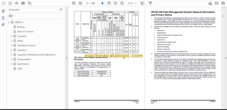
- The Value of the Carbon Dioxide (CO2) Emissions
- DEVELON Fleet Management System General Information and Privacy Notice
- Safety
- Safety Decals
- Information and Location for Safety Decals
- General
- Safe Operation is Operator’s Responsibility
- Know Your Machine
- Proper Work Tools and Attachments
- Pressurized Fluids
- Flying or Falling Objects
- Personal Protective Equipment (PPE)
- Correction of Machine Problems
- Crushing and Cutting
- Hot Coolant and Oils – Burn Prevention
- Fire and Explosion Prevention
- Fire Extinguisher and First-Aid Kit (Emergency Medical Kit)
- Electrical System and Electrical Shock
- Roll-over Protective Structure (ROPS)
- Regulation 8.35(2) of the Mines Safety and Inspection Regulations (1995)
- Transportation
- Obey State and Local Over-the-Road Regulations
- Loading and Unloading
- Transporting Machine
- Operation
- Before Engine Starting
- Work Site
- Mounting/Dismounting
- Cleaning
- Operator Station
- Seat Belt
- Visibility Information
- Boost Starting or Charging Battery
- Starting Engine
- Swinging or Traveling
- Lifting and Digging
- Operation on Slopes
- Towing
- Attachment
- Equipment Lowering with Engine Stopped
- Engine Stop
- Parking Machine
- Preservation/Storing Machine
- Maintenance
- Warning Tag
- Cleaning
- Proper Tools and Clothing
- Disassembling Precautions
- Use of Lighting
- Fire and Explosion Prevention
- Burn Prevention
- Rubber That Contains Fluorides
- Rubber and Plastics
- Welding Repairs
- Warning for Counterweight and Front Attachment Removal
- Lock Inspection Covers
- Working on Machine
- Accumulator
- Compressed Air
- Track Tension Adjustments
- Supports and Blocking for Work Equipment
- High-pressure Lines, Tubes and Hoses
- Battery
- Environment and Circumstances
- Work Site Areas Requiring Extra Caution
- High-voltage Cables
- Underground Operation
- Working in Water
- Working in Contaminated Environment
- Operation in Extreme Conditions
- Exhaust Ventilation
- Asbestos Information
- Silica Dust Information
- Disposal of Hazardous Materials
- Sound
- Vibration Information
- Operating Controls
- Component Locations
- Operator’s Area
- Operational Controls and Panels
- 1. Starter Switch
- 2. Heater and Air Conditioner Control Panel
- 3. Power Socket for 12 Volt
- 4. Engine Emergency Stop Switch
- 5. Engine Speed Control Dial
- 6. Light Switch
- 7. Audio Control Panel
- 8. Quick Coupler Switch (Optional)
- 9. Warning Light Switch (Optional)
- 10. Wiper Switch
- 11. Windshield Washer Switch
- 12. Boom Swing Switch (Optional)
- 13. Horn Button (Left-hand Work Lever)
- 14. Breaker Button (Right-hand Work Lever)
- 15. Rotating/Boom Swing Switch
- 16. Shear Switch
- 17. Display Monitor
- 18. Safety Lever
- 19. Diesel Particulate Filter (DPF) Switch
- 20. Hour Meter
- 21. Jack Assembly
- 22. 2-speed Button
- Display Monitor
- Functional Check
- Password Activated
- 1. Fuel Gauge
- 2. Engine Coolant Temperature Gauge
- 3. Engine Speed Control Dial Gauge
- 4. ECO Gauge
- 5. Warning Light
- 6. Digital Clock
- 7. Display Warning Symbols
- 8. Engine Speed
- 9. Selector Function Display
- 10. Function Buttons
- Warning Pop-up Window
- User Menu
- User Menu – Access and Escape Methods
- Heater and Air Conditioner Control Panel
- Location of Controls and Vents
- Control Panel
- Memory Function
- Additional Operating Instructions
- Stereo
- Miscellaneous Electrical Devices
- Cabin Light
- Battery Disconnect Switch
- Pilot Cutoff Switch
- Circuit Breaker
- Fusible Link
- Fuse Box
- Seat Adjustment
- 1. Forward / Backward Adjustment
- 2. Seat Height Adjustment
- 3. Suspension Adjustment
- 4. Backrest Adjustment
- 5. Armrest Angle Adjustment
- 6. Lumbar Support Adjustment
- 7. Headrest
- 8. Seat Belt
- 9. Seat Back-pocket
- 10. Heating the Operator’s Seat (Optional)
- 11. Two-grade Forward / Backward Adjustment
- 12. Seat Forward / Backward Adjustment
- 13. Seat Angle Adjustment
- Front Windows
- Front Upper Window
- Front Bottom Window
- Door Side Latch
- Cabin Storage Compartments
- Sun Visor (Optional)
- Hanger
- Emergency Exit Glass Breaking Tool
- Operation
- To operate a New Excavator
- Starting and Stopping Engine
- Inspection Before Starting Engine
- Operational Checks Before Starting Engine
- Engine Start
- Cold Weather Starting
- Starting Engine With a Booster Cable
- Hydraulic System Warm-up
- Hydraulic System Warm-up – Cold Weather
- Check and Confirmation After Engine Start
- Stopping Engine
- Check and Confirmation After Stopping Engine
- Safety Lever
- Travel
- Travel Speed Control
- Travel Control Lever Operation
- General Travel Instructions
- Operating Instructions
- Engine Speed Control
- Engine Exhaust Emission Control System
- Work Levers (Joysticks) (ISO Pattern)
- Change Machine Control Pattern by Selector Valve (If Equipped)
- Work Levers (Joysticks) (BHL Pattern)
- Blade Control Lever
- Operating Precautions
- Operation Under Water or On Weak Ground
- Parking Excavator
- Towing Procedure
- Hydraulic Breaker
- Selection of Hydraulic Breaker
- Hydraulic Hoses and Tubing for Breaker
- Hydraulic Breaker Operation
- Hydraulic Oil and Filter Service Intervals
- Boom Swing Operation (Optional)
- Shear Operation
- Two – Piece Boom (Optional)
- Quick Coupler Operation
- Lifting Objects
- Lifting Objects with Quick Coupler
- Operation Under Abnormal Conditions
- Operation In Extreme Cold
- Operation in Extreme Heat
- Operation in Dusty or Sandy Areas
- Operation in Rainy or Humid Conditions
- Operation in Salt Water Areas
- Operation at High Altitudes
- Operation During Electrical Storms
- Equipment Lowering with Engine Stopped
- Long Term Storage
- Inspection, Maintenance and Adjustment
- Maintenance Information
- Machine Setup Position for Maintenance
- Table of Recommended Lubricants
- Coolant and Water for Dilution
- Fluid Capacities
- Lubrication and Service Chart
- Maintenance Intervals
- 10 Hour / Daily Service
- Grease Dozer, Boom Swing and Front Attachment Pins (for first 100 hours)
- Check Engine Oil Level
- Check Level of Hydraulic Oil Tank
- Check for Leaks in Hydraulic System
- Check Fuel Level
- Check for Leaks in Fuel System
- Check Water Separator & Pre Fuel Filter (Fuel Prefilter) and Drain Water as Required
- Check Additional Water Separator and Drain Water as Required (If Equipped)
- Check Oil Level of Swing Reduction Device
- Check Cooling System and Refill as Required
- Check Level of Window Washer Liquid
- Inspect Bucket Teeth and Side Cutters for Signs of Wear
- Inspect Cooling Fan Blade
- Check Air Intake System
- Inspect Seat Belt for Proper Operation
- Inspect the Structure for Cracks and Faulty Welds
- Check the Operation of All Switches
- Check Operation of All Exterior Lights, Horn and Control Console Indicator and Display Monitor
- Start Engine, Check Starting Ability, and Observe Exhaust Color at Start-up and at Normal Operating Temperature. Listen for Any Abnormal Sounds
- Check Operation of All Controls and Linkages
- 50 Hour / Weekly Service
- Perform All Daily Service Checks
- Grease Dozer Pins
- Grease Boom Swing Cylinder and Bracket
- Grease Swing Bearing
- Drain Water and Sediment from Fuel Tank
- Check Engine Fan Belt for Cracks, Wear and Correct Tension (After First 50 Hours)
- Inspect the Track Assemblies for Proper Tension and Loose, Worn or Damaged Parts (Links, Shoes, Rollers, Idlers)
- 250 Hour / Monthly Service
- Perform All Daily and 50 Hour Service Checks
- Grease Front Attachment Pins
- Change Engine Oil and Filter
- Check Engine Fan Belt Tension
- Check Engine Fan Belt Wear
- Check Oil Level in Travel Reduction Device (One on Each Side of Unit)
- Clean Outer Filter of Air Cleaner
- Change Oil in Travel Reduction Device (One on Each Side of Unit) (After First 250 Hours)
- Change Swing Reduction Device Oil (Drain and Refill After First 250 Hours)
- Replace Hydraulic Oil Return Filter (After First 250 Hours)
- Change Pilot Filter (After First 250 Hours)
- Inspect Pins and Bushings of the Front End Attachments for Signs of Wear
- Check Fluid Levels in Batteries
- Inspect for Any Loose or Missing Nuts and Bolts
- Inspect Fuel System Hose Clamps
- 500 Hour / 3 Month Service
- Perform All Daily, 50 and 250 Hour Service Checks
- Grease Swing Gear and Pinion
- Change Main Fuel Filter
- Change Water Separator & Pre Fuel Filter (Fuel Prefilter)
- Change of Water Separator & Pre Fuel Filter (Fuel Prefilter) (If Equipped)
- Replace Hydraulic Oil Return Filter
- Clean Air-conditioning Inner Filter
- Clean Air-conditioning Outer Filter
- 1,000 Hour / 6 Month Service
- Perform All Daily, 50, 250 and 500 Hour Service Checks
- Change Oil in Travel Reduction Device (One on Each Side of Unit)
- Change Swing Reduction Device Oil
- Change Pilot Filter
- Grease Swing Reduction Gear
- Change Air-conditioning Inner Filter
- Change Air-conditioning Outer Filter
- Clean Hydraulic Oil Suction Strainer
- Change Air Breather Element
- Change Fuel Cap Filter
- Check Air Conditioner Refrigerant
- Check and Adjust Engine **
- Replace Outer and Inner Air Cleaner Filters
- 2,000 Hour / Yearly Service
- Perform All Daily, 50, 250, 500 and 1,000 Hour Service Checks
- Change Radiator Coolant
- Change Hydraulic Oil
- Check Alternator and Starter **
- Check All Rubber Antivibration Shock Mounts
- Perform and Record the Results of the Cycle Time Tests
- Inspect Machine to Check for Cracked or Broken Welds or Other Structural Damage
- Check, Adjust Valve Clearance **
- Check Head Bolt Torques
- 4,000 Hour / Biennial Service
- Major Parts – Periodic Replacement
- 6,000 Hour / Biennial Service
- Clean Diesel Particulate Filter (DPF)
- 9,000 Hour / 4 Year Service
- Change Diesel Oxidation Catalyst (DOC) and Diesel Particulate Filter (DPF)
- 12,000 Hour / 6 Year Service
- Hose In-service Lifetime Limit (European Standard ISO 8331 and EN982 (CEN))
- Bucket
- Bucket Tooth Replacement
- Bucket O-ring Replacement
- Bucket Shimming Procedures
- Replace Bucket
- Electrical System
- Engine Cooling System
- General
- Measuring the Concentration of Coolant
- Antifreeze Concentration Tables
- Table of Standards for Allowed Tap Water
- Fuel Transfer Pump (Optional)
- Handling of Accumulator
- Track Tension
- Venting and Priming Hydraulic System
- Main System Pump
- Hydraulic Cylinders
- Swing Motor
- Travel Motor
- General Venting
- Maintenance in Special Conditions
- Transportation
- Loading and Unloading
- Lifting Machine
- Specification
- Standard Specification
- Overall Dimensions
- One – Piece Boom
- Two – Piece Boom
- Working Range
- One – Piece Boom
- Two – Piece Boom
- Excavator Rated Lift Capacity Tables
- Approximate Weight of Workload Materials
- Index
Develon


