Format: PDF (Printable Document)
File Language: English
File Pages: 770
File Size: 170.87 MB (Speed Download Link)
Brand: Doosan (Daewoo)
Model: DA30 Articulated Dump Truck
Type of Document: Shop Manual
$ 40
Chapter 00 – General
Foreword
Torque limit table
Types of sealing-/locking compounds and lubricants
Safety in workshop
Working on machine
Personal Protective Equipment (PPE)
Vibration
Injurious noise
Organic solvent
Fueling
Fire and Explosion Prevention
Fire and explosion risks
In case of Fire
Coolant
Refrigerant
Air pollution
Operation in extreme conditions
Liquid or gas under high pressure
Asbestos
Lead
Battery hazard prevention
Disposal of hazardous materials
Jacked up vehicle or bodywork
Crushing and Cutting Danger
Heavy units
More than one person working with the same object
Involuntary start of electric motors etc.
Rotating parts
Splinters, flying object When using certain tools
Springs under load
Precautions for disassembly and assembly
Chapter 01 – Engine
Engine identification
Removal of engine assembly
Lifting the engine
XPI Fuel system DA30/40
Route of the fuel on 9 and 13 litre engines
Fuel filter and water separation
Overflow valve
Fuel system components
Schematic diagram of the fuel system:
Important information about the fuel
Exhaust system XPI
Introduction System overview
Control system for exhaust gas aftertreatment
Control unit EEC3
System overview for mechanics
System overview for electrics
Ad blue filter change
Reductant doser
Reductant pump, function
Start-up instruction for new SCR Pump
Fuel system Tier2 (PDE)
Schematic diagram of the fuel system Tier2
Overflow valve
General
FUEL
Temperature dEpendency of the Fuel
Fuel filter
Changing the fuel filter
Water separating prefilter XPI
changing the water separating fuel filter
Bleeding the fuel system
Feed pump
Diagnostic prosedure
Use of diagnostic kit, Tier 2
Connection point Can pc VCU + Testman
Can bus overview
Connection point SDP3 Scania dagnostic
Renewing the control unit
Removing the ECU wiring Tier2
Cylinder head – PDE System Tier2
Cylinder head, parts view. PDE Tier2
Special tools
Valve mechanism
Dismantling
Renewing the valve stem seal
Replacement of valve seats
Machining the valve seats insert
Renewing the valve guides
Renewing PDE unit injector sleeves
Assembly
Fitting
Common rail Injectors Tier4/XPI
Cylinder head – XPI system Tier4
Cylinder head, parts view. XPI system Tier4
Injector Scania XPI
Valve adjustment DC13 with XPI
Order of adjustment for 13 litre engines
Cylinder configuration, 6 cylinder engines
Valve adjustment DC9 with XPI
Cylinder configuration, 5 cylinder engines
Valve adjustment DC13 with PDE
Adjusting unit injectors
Adjusting the valve clearance and unit injectors
Checking, adjusting the PDE injector and rocker arms
Valve adjustment DC9 with PDE
Checking, adjusting the PDE32 injector and rocker arms (I)
Turbocharger
General
Changing oil filter
Oil analysis
Checking oil level
Changing the oil
Special tools
Measuring radial clearance and axial clearance
Renewing the turbocharger
Pistons and cylinder liners
Special tools
Connecting rods
Removing and dismantling connecting rods and pistons
Renewal of bearing bushing in connecting rod
Pistons
Assembling piston and connecting rod
Cylinderblock
Cylinder liner
Removing the cylinder liners
Measuring the cylinder liner height
Measuring the cylinder wear ridge and cylinder bore
Fitting the cylinder liners
Fitting the piston and connecting rod
Flywheel and flywheel housing
Special tools
Removing the flywheel
Renewing the rear crankshaft seal
Removing the flywheel housing
Fitting flywheel housing
Fitting the flywheel
Timing gear, 13 litre with unit injector
Gear drive
Belt drive collant pump, generator and AC compressor
Checking the Drive Belt
Check for leaks
Renewing the seal in the front cover
Crankshaft damper
Timing gear, view exploded
Special tools
Intermediate gear
Camshaft gear
Crankshaft gear
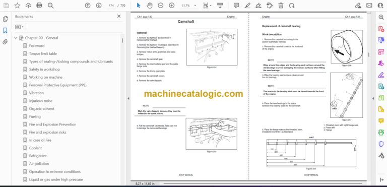
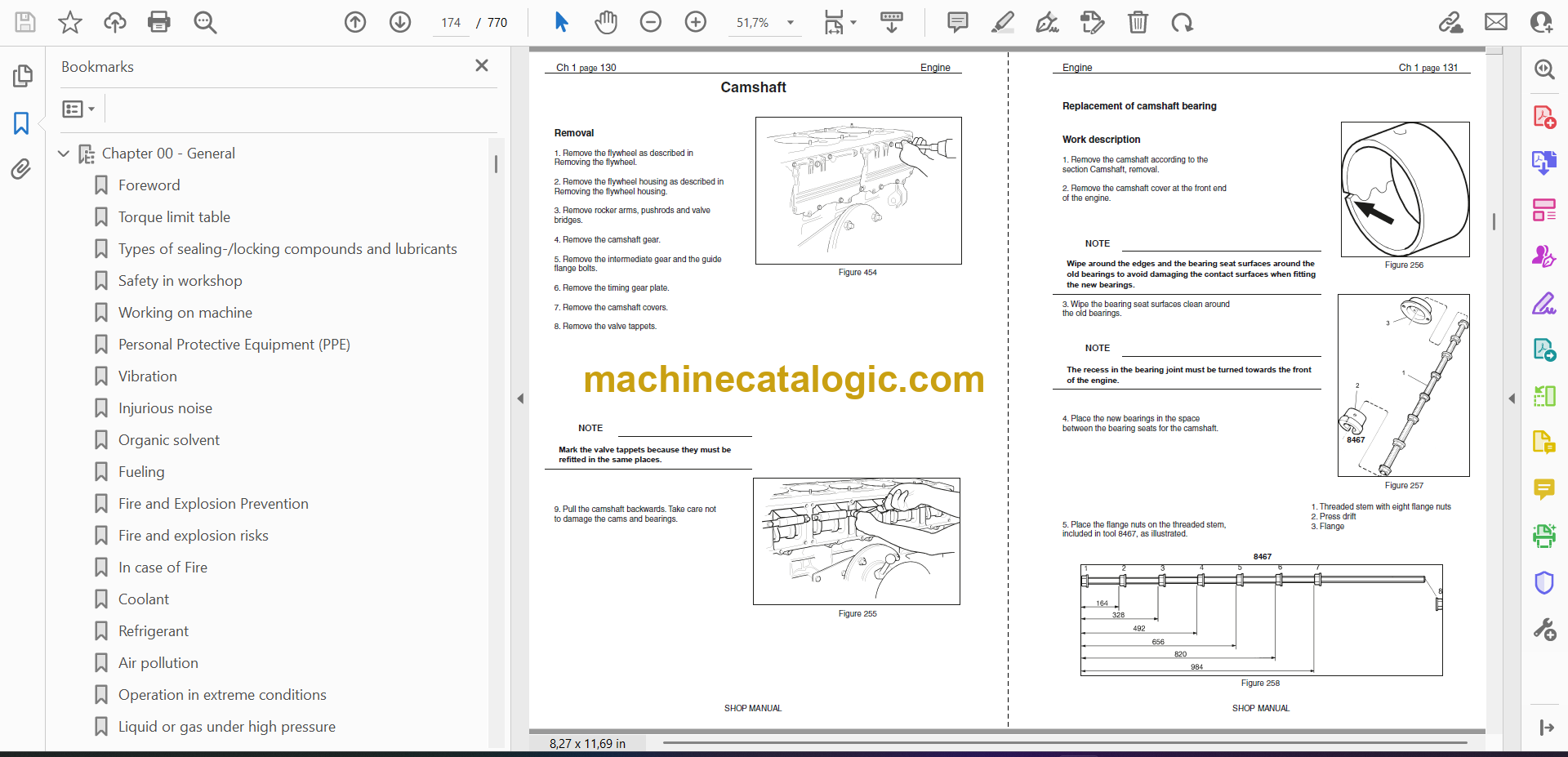
Camshaft
Replacement of camshaft bearing
Crankshaft
Removal
Fitting
Adjust – Machining the crankshaft
Lubrication system
Oil pump
Lubrication oilways
Oil pressure
Oil cooler, engine
Oil cooler view Se 010009
Renewing seals and leakage testing
Oil filter
Centrifugal oil cleaner
Dismantling and assembly
Oil mist separator
General
High levels of oil carryover
Crankcase pressure measurement
Oil mist separator exploded view
Oil mist separator disassemble
Check – Rotational speed on oil mist separator
Alternator 100 A
Check
Output test
Renewal – Bearing and carbon brushes
Oil pump, brake cooling circulate (DA40)
Exploded view
Disassemble and overhaul the oil pump
Checking and renewing parts
Oil circulate pump assemble.
Renewing the gasket
Cooling fan
View of the radiator system DA40
Cooling system
Principal view of the cooling system
Circulation
Coolant
Checking Coolant Level
Checking the Antifreeze Level
Changing Coolant
Cleaning the Cooling System
Disassemble the cooling unit
Thermostat and thermostat housing
Thermostat
Coolant pump
External cleaning
Internal cleaning
Technical data DC13 with XPI
General data
Technical data DC9 with XPI
General data
Technical data DC13 with PDE
General data
Technical data DC9 with PDE
General data
Troubleshooting ECOM / Canbus
To do:
Troubleshooting, -basic info.
Troubleshooting fuel system
Troubleshooting Guide
Troubleshooting Manual
White smoke
White smoke, water vapour
White smoke, water vapour
Black smoke on starting
Blue smoke
Fuel in the oil
Oil in coolant
Coolant/water in oil
Low oil pressure
High oil pressure (engine warmed up)
Abnormal wear (liner, piston rings, etc.)
Vibration, no driven components engaged
Vibration when the clutch or reverse gear is engaged
Vibration when alternator is in operation
Engine speed hunting – single-speed engines with RQ governor
Engine speed hunting – single-speed engines with RSV governor
Delivery pipe fractures
External corrosion on cylinder liner
Engine difficult to start
Fluid stroke
Knocking/noise
High oil consumption
High fuel consumption
Low compression
Low engine output
Hot engine
Cold engine
Coolant loss
Polluted coolant
Polluted coolant
High oil temperature
High exhaust temperature
Low charge air pressure
Low fuel pressure
Low system voltage
High system voltage
External oil leakage
External fuel leakage
External coolant leakage
Oil pressed out via crankcase ventilation
Turbocharger breakdown
Compressed air system
Chapter 02 – Transmission
GENERAL
Structure of the Repair Manual
Denomination of standard dimensions
Conversion table
Torque limits for screws.
Table
Labeling of type plate
Information on spare parts ordering
Configuration of transmission
Transmission schematics and gear schematics
Measuring points and connections
Table
Clutch calibration
Installation sheet
Specjal tools for disassembly and reassembly
Commercial tools for disassembly and reassembly
Removal of transmission, disass’y
Disassemble the structure bar
Disassemble the hydraulic hoses
Positioning for disassembly and reassembly
Removal and refitting various components
Transmission
LKV axle insert
Removal and refitting of speed sensor n4-output
Removal:
Retting:
Removal and refitting of solenoid valves of shifting block II and temperature sensors
Removal:
Retting:
Disassembly and reassembly of shifting block I and speed sensors
Disassembly:
Reassembly:
Removal and refitting of LKV axle insert
Separation of LKV axle insert from transmission:
Attachment of LKV axle insert to transmission
Sealing of outputs towards rear axle and LKV axle insert
Exchange of shaft seal ring towards LKV axle insert
Removal of shaft seal ring
Fitting of shaft seal ring:
Exchange of shaft seal ring towards rear axle
Removal of shaft seal ring
Fitting of shaft seal ring
Transmission assembly
Chapter 03 – Drive line and brakes
Introduction
General
Structure of the Repair Manual
Denomination of standard dimensions
Conversion table
Tightening torques for nuts and bolts.
Table
Drive line components
Front reduction gear
DA30 parts list
Front reduction gear cross section
NAF special Tools for DA30
Assembly
Drive shafts
Front frame
Rear frame
Mounting the bearings on the intermediate shaft (B)
Front differential and transmission
Brakes
Service brakes (DA30)
Service brake description
Testing of parking brake
Remove the Linings
Disassembly the park brake unit
Assembly the park brake unit.
Adjust the Initial Caliper Clearance
Park brake Maintenance
Disc
Troubleshooting Park brake
Rear differential
Rear Differential, DA30
Exchange of the complete rear differential
Safety precautions.
Disassemble the tandem unit from the rear frame
Repairs on the rear differential
Exchange of crown gear / Pinion
Determining thickness of the adjusting washer (44)
Determining thickness of the adjusting washer (45)
Pinion bearing adjustment
Backlash and crown gear bearing adjustment
Checking contact pattern
Exchange shaft seals
Exchange of differential cage (compensating gearbox)
Differential lock
Planetary drive
Complete exchange of planetary cage
Exchange of sun gear shaft
Exchange of Planetary Studs and Gears
Exchange of ring gear carrier
Wheel bearings
Gear bearing exchange
Gear bearing adjustment
Brake
Check disc’s wear
Exchange of the piston for the operating brake
Exchange of brake disks and pressure springs for the operating brake
Tandem bearings
Exchange of slewing ring
Exchange of seal
Exchange of axle beam
Gear drive in tandem housing
Exchange of bearing (84)
Exchange of gear (43) and bearing (89) / (90)
Exchange of gears (86)
Checking clearance in the Tandem bearing.
View of the Tandem bearing
Special Tools for Mox 08 axle
Chapter 04 – Lubrication
Lubrication system parts
Greasing cycles
Lubrication Points on DA series
Grease pressure switch
The 5/2 way valve
The relief valve
The minimum level switch
System test
Introduction
The single-test cycle
The continuous-test cycle
Warning signal
Maintenance
Regulary checks of the greasing system
Bleeding the pump
Bleeding the system
Technical data
Dimensions of the Twin Pump
Chapter 05 – Hydraulic system One Pump Solution
Components, capacities and oil types
Startup test procedure
Main Pump
Steering system
Tilting system
Fan system
Brakes
Accumulators
Chapter 06 – Electrical system
How to use the electrical documentation
Troubleshooting, what to do
Description of the VCU2 functionality
Doosan Moxy VCU 2
Find wiring contact on VCU2
LCD Instrumentation Unit
Warning Lights Display
LCD screen main menu
LCD use description
Pos reference list
Description of the main electrical system.
General description
Welding on the dump truck
Battery hazard prevention
Component position
Electrical parts view
El.system, outside front and rear
Electrical equipment inside cab
El.system, Cab inside
Switch panel
Heater unit exploded
Heater unit parts list
Ignition key switch Pos 49
Air conditioning system componenets
Product final inspection
Safety measures
Refrigerant charging
Regulation controll
Use of the A.T.C
Central lubrication main unit, (overview)
Rear frame
DA series functions and parameters
Brake/brake charge system (Accumulators) (7)
WDB Cooling (only on DA40) (7)
Emergency Steering system (9)
Park brake (6)
Low engine oil pressure (2)
Low coolant level (3)
Clogged air filter (4)
Central lubrication pump (11)
Charge lamp (12)
Body tip system (13)
Load weighing (32)
Differential lock (28)
Cooling fan control
Quick warmup function
Cooldown function
Alternative engine speed
Interior light
Retarder and Engine brake (24 – 25)
Emergency Stop
Fuel Heater
A/C compressor control
To be implented
Engine electrical components.
Engine EMS S6 / S8
Electrical cable routing
EMS connection chart
EMS pin list
Engine Management System S8
Engine speed and camsghaft sensors
Wastergate solenoid valve
Control unit EMS S8
Fuel pressure sensor
Fuel inlet metering valve
Solenoid valve for XPI injector
Transmission spesification of electrical components
Transmission speed sensors
Transmission temperature sensors
Transmission solenoid valves
Transmission pressure switch
Transmission electric switch
Sensors hydraulic system
Steering valve, el. connection
Main valve el. connection
Parking brake sensor
Body float sensor
Electrical chart and circuit
Cab roof cable set
Cab floor cable set
Cab inside rear wall cable set
Wiring (cable set) S1 – S6
Cirquit chart cabine (No1)
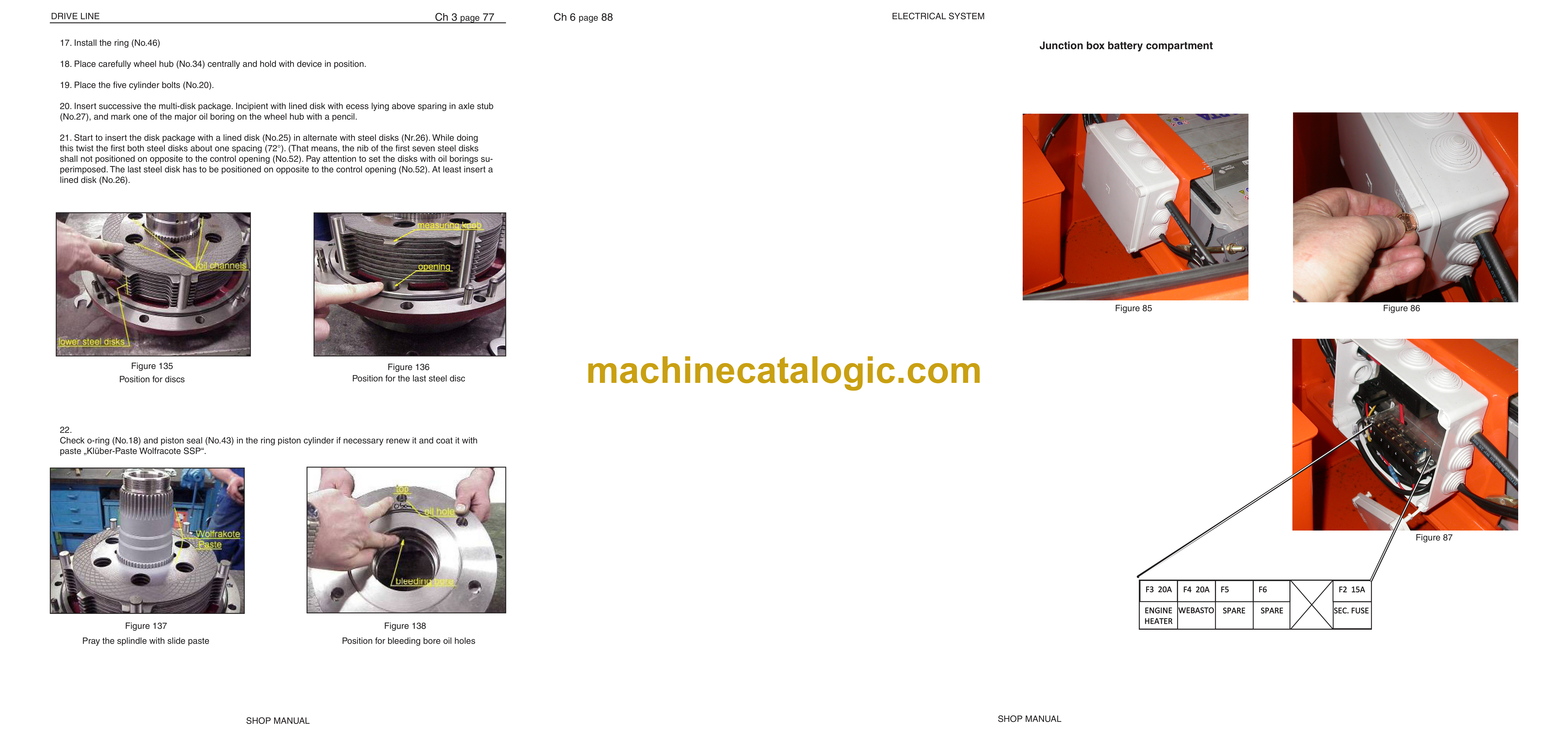
Junction box battery compartment
Cirquit chart front and rear frame (No2)
Exhaust Emmission Control
Wiring diagram for the exhaust emission control
System overview for electrics
Chapter 07 – Front wagon
7.1 Introduction
View of the fron axle suspension
Disassemble of the front axle arm
7.2.1 Shock Absorber
7.2.2 Chain Limiter
7.2.3 Rubber Cushion
7.2.4 Panhard Bar
7.2.5 Suspension Bearing
7.2.6 Cross Tube Bushings
7.3.1 Articulation Bearing
7.3.3 Articulation Hinge
7.4.1 Fender RH
7.4.2 Fender LH
7.4.3 Mudguard
7.4.4 Bonnet Lock
7.4.5 Bonnet
7.4.6 Bonnet adjustment and control
7.5.1 Cab Removal
7.5.2 Cab Ventilation Control Panel
7.5.3 Cab Ventilation Unit
7.5.4 Cab Door
7.5.5 Door Damper Cylinder
7.5.6 Steering Column
Chapter 08 – Rear wagon
8.1 Introduction
8.2.1 Dumper Body
8.2.2 Tilt Bearing
Chapter 09 – Option
9 Optional Equipment
9.1 Automatic Tail Gate
9.2 Exhaust Heating For Dumping Body
9.2.1 View of the Exhaust Body Heating System
9.2.2 Assembly of The Exhaust Body Heating System
9.3 View of the Engine heater
9.3.1 Engine heater assembly
9.4 Dust bowl
9.5 Webasto
Chapter 10 – Error codes list
English

