Format: PDF (Printable Document)
File Language: English
File Pages: 716
File Size: 35.77 MB (Speed Download Link)
Brand: Doosan (Daewoo)
Model: D100, D120 Excavator
Type of Document: Service Manual
$ 40
Chapter 00 – General
0 General
0.1 Introduction
0.1.1 Important information on Industrial Safety
0.2.1 Incidents are warning signals
0.2.2 Vibrations
0.2.3 Injurious Noise
0.2.4 Organic Solvents
0.2.5 Coolant
0.2.6 Refrigerant
0.2.7 Air Pollution
0.2.7 Liquid Or Gas Under High Pressure
0.2.8 Fire And Explosion Risks
0.2.9 Asbestos
0.2.10 Lead
0.2.11 Jacked Up Vehicle Or Bodywork
0.2.12 Heavy Objects
0.2.13 Protection Against Damage And Injury
0.2.13 More than one person working on the same Vehicle
0.2.14 Involuntary Start of Electric Equipment
0.2.15 Rotating Parts
0.2.16 Splinters, Flying Object When Using Certain Tools
0.2.17 Springs Under Load
0.2.18 Tyres and Wheels
0.2.19 Precautions for Disassembly and Assembly Operations
0.2.19.1 Types of sealing-/locking Compounds and Lubricants used during Assembly
0.2.19.2 Torque limits for screws
0.2.20 Handling of Oil Seals
0.2.21 Handling of Gaskets
0.2.22 Handling of O-ring Seals
0.2.23 Handling of Bearings
0.3 Precaution before any Maintenance Operation
0.4 Location of Main Components
0.5 Location of Drive Line Main Components
Chapter 01 – Engine Tier3
Removal of engine assembly
Lifting the engine
Engine identification
Fuel system
Schematic diagram of the fuel system
Overflow valve
General
FUEL
Fuel filter
Water separating prefilter
Feed pump
Diagnostic prosedure
Use of diagnostic kit, machine
Measurement
Ecom standard settings code
Engine control unit, ECU
Wiring and cable duct
Throttle position sensor
Positions of sensors for ECU
Diagnostic lamp and switch
Fault codes
How to read fault codes from the ECU control unit
Flash codes tables
Overview of flash codes for coordinator
Renewing the control unit
Removing the ECU wiring
Cylinder head
Special tools
Cylinder head, parts view.
Valve mechanism
Dismantling
Renewing the valve stem seal
Replacement of valve seats
Machining the valve seats insert
Renewing the valve guides
Renewing PDE unit injector sleeves
Assembly
Fitting
PDE Injectors
Fitting the PDE injector
Adjusting unit injectors
Adjusting the valve clearance and unit injectors
Checking, adjusting the PDE32 injector rocker arms (I)
Turbocharger
General
Special tools
Measuring radial clearance and axial clearance
Renewing the turbocharger
Pistons and cylinder liners
Special tools
Connecting rods
Removing and dismantling connecting rods and pistons
Renewal of bearing bushing in connecting rod
Pistons
Assembling piston and connecting rod
Cylinderblock
Cylinder liner
Removing the cylinder liners
Measuring the cylinder liner height
Fitting the cylinder liners
Fitting the piston and connecting rod
Flywheel and flywheel housing
Special tools
Removing the flywheel
Renewing the rear crankshaft seal
Removing the flywheel housing
Fitting flywheel housing
Fitting the flywheel
Timing gears
Gear drive
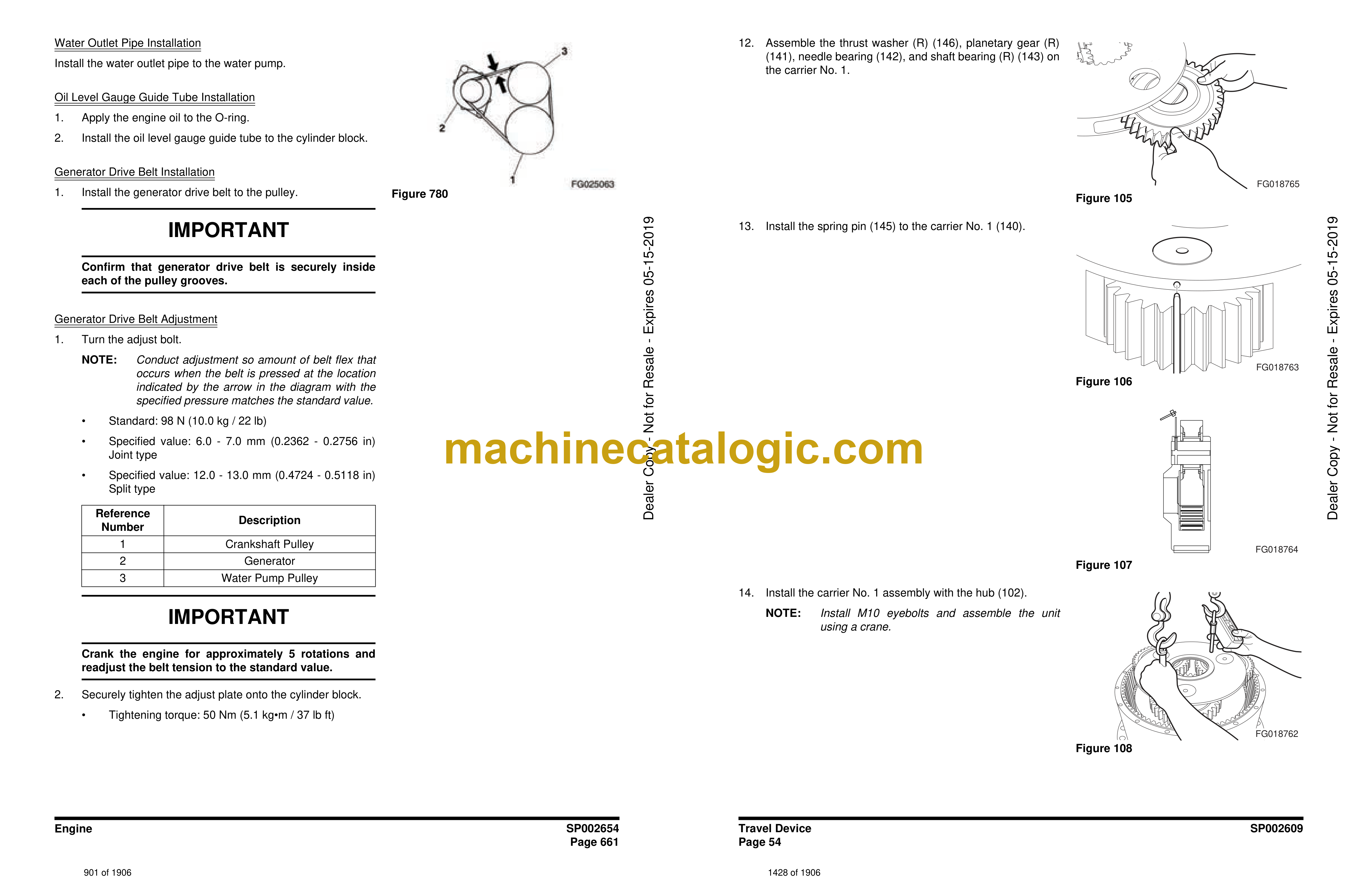
Belt drive collant pump, generator and AC compressor
Renewing the seal in the front cover
Crankshaft damper
Timing gear, view exploded
Special tools
Crankshaft seal
Timing gear cover
Intermediate gear
Crankshaft gear
Camshaft gear
Camshaft
Crankshaft
Lubrication system
Oil pump
Lubrication oilways
Oil pressure
Oil cooler, engine
Oil cooler view
Renewing seals
Oil filter
Centrifugal oil cleaner
Dismantling and assembly
Cooling fan
Cooling system
View of the cooling system
Circulation
View of the radiator system
Disassemble the cooling unit
Thermostat and thermostat housing
Thermostat
Coolant pump
External cleaning
Internal cleaning
Specifications
General information
Cylinder head
Turbocharger
Pistons and cylinder liners
Connecting rods
Flywheel and flywheel housing
Timing gear
Lubrication system
Troubleshooting tables
White smoke
White smoke, water vapour
Black smoke when running/under load
Black smoke on starting
Blue smoke
Fuel in the oil
Oil in coolant
Coolant/water in oil
Low oil pressure
High oil pressure (Engine warmed up)
Abnormal wear (liner, piston rings, etc.)
Vibration, no driven components engaged
Delivery pipe fractures
External corrosion on cylinder liner
Engine difficult to start
Fluid stroke
Knocking noise
High oil consumption
High fuel consumption
Low compression
Low engine output
Hot engine
Cold engine
Coolant loss
Polluted coolant
Engine heater
High oil temperature
High exhaust temperature
Low charge air pressure
Low fuel pressure
Low system voltage
High system voltage
External oil leakage
External fuel leakage
External coolant leakage
Oil pressed out via crankcase ventilation
Turbocharger breakdown
Chapter 02 – Transmission Page 01-90
GENERAL
Structure of the Repair Manual
Denomination of standard dimensions
Conversion table
Torque limits for screws.
Table
Technical data
Description:
Transmission cross section
Oil temperatures:
Oil grade
Oil level check:
List of lubricants
Oil change and Filter replacement interval:
Oil level check.
Oil change and Oil filling capacity:
Filter replacement:
Fine filter:
Axle insert „LK“:
Oil specification:
Oil change:
Controller
Clutch chart
Circuit diagram controller
Coding controller
Display
OPERATION
Driving preparation and Maintenance
Driving and Shifting
Transmission control in the Driving mode Automatic:
Testing system, ZF
Safety notice
Diagnostic – set
Installation of Diagnostic Software –> Testman
Start of Testman
Produkt menue Ergopower
AEB starter
AEB calibration
Automatic calibration of the Shifting elements
Procedure to start AEB
AEB code list
Laptop – Start of AEB via Testman
Installation view
Inductive transmitter
Transmission diagram
Oil circuit diagram
Valve block controll circuit
Measuring points and connections
Troubleshooting
Prerequisites for the troubleshooting
Lay out 6WG-260
Introduction
ZF – Display:
Display during operation
Display during AEB-Mode
Definition of operating modes
Table of fault codes
Measuring of resistance at actuator/sensors and cable
Electronic Control unit EST-37A
Important parts information
Pin in contact for the TCU
Family package of the EST-37A
Electro-hydraulic shift control unit
Transmission control:
Electro-hydraulic control unit HSG-94
Electro hydr. shift control valve, cross section
DISASSEMBLY
ASSEMBLY
WK-Valve
WK Solenoid shift valve
DISASSEMBLY
Retarder
Function of a retarder
Retarder reconditioning tool
Disassembly the retarder
ASSEMBLY
Retarder valve
Converter
Function of the Converter:
Converter (WK)
Removal of transmission, ass’y
Disassemble the exhaust parts
Disassemble of the hydraulic hoses at the transmission
Manual transmission
Disassembly
Axle disconnection
Interaxle differential:
Description:
Interaxle differential with mounted Differential carrier „LK“
Interaxle differential disassembly
Clutches, Powershift transmission
Multi-disk clutch
Clutch chart
Plate clearanse in the single Multi-disc clutches
Oil circuit diagram
Disassemble Multi-disc clutches
Dismantle multi-disc clutch KR/K2
Manual transmission assembly
Multi-disc clutch-K3
Multi-disc clutch-KR
Multi-disc clutch-K2
Clutch-KV
Multi-disc clutch-K1
Interaxle differential assembly
Adjust bearing pre-load of the clutches
Install emergency steering pump
Transmission control. The pump
Hydraulic pump
Axle disconnection – version with intermediate axle differenti
Input converter bell
Inductive transmitters and speed sensor
Assembly and settings
Differential Carrier „LK“
Tools
Disasembly
Assembly
Differential DL-2400, Interlock value 45%
Mount Differential carrier on the Transmission
Chapter 02 – Transmission Page 091-208
Chapter 02 – Transmission Page 209-310
Chapter 03 – Drive line and brakes
Chapter 05 – Hydraulic System
Components, capacities and oil types
Startup test procedure
Main pump
Steering system
Tilting system
Fan system
Brakes
Accumulators
Chapter 06 – Electrical System
Description of el. system
General description
Welding on the dump truck
Battery hazard prevention
How to use the electrical documentation
Faultfinding, what to do
Practical example
Description of circuit symbols
Electrical parts view
Spesification of electrical components.
Flashing code list for the EMS control unit.
General coordinator connection diagram 710655 –
Coordinator description (Scania) page 1. 710655 –
Coordinator description (Scania) page 2. 710655 –
Spesification of electrical components
CT1 introduction
CT1 Tecnical data
Position list.
List
Map
Map 01 El.system, outside front and rear
Map 02 El.system, Front frame
Map 03 El.system, Rear frame
Map 04 El.system, Sensors on Engine
Map 05 El.system, Sensors on Engine
Map 06 El.system, Sensors on Transmission
Map 07 El.system, Cab outside and ceiling
Map 08 Cab lower
Map 09 Fuse box and relays
Map 10 Heater unit
Map 11 El.system, Instrument panel
Map 12 Cab innside, lower panel
Circuits
Circuit 01 Compartment and cab light
Circuit 02 Brake light
Circuit 03 Power supply / start
Circuit 04 Work light / Extra high beam
Circuit 05 Heated mirrors
Circuit 06 Fan and A/C
Circuit 09 Rewerse and work light rear
Circuit 10 Gauge and Instrument light
Circuit 10 Gauge and Instrument light. 810053-
Circuit 11 Lighter
Circuit 12 Rotating beacon
Circuit 13 Radio
Circuit 14 Wiper, washer and horn
Cirquit 15 Seat belt warning
Cirquit 16 Heated chair and chair compressor
Cirquit 18 Engine serial no: 810001 – 810035
Cirquit 18 Engine serial no: 810036-810052
Cirquit 18 Engine serial no: 810053-
Cirquit 19 Transmission serial no. 810001-810052
Cirquit 19 Transmission serial no. 810053-
IVC4B Connector pinout
EST 37 pinout
Cirquit 20 Brake warning light 810001 – 810052
Cirquit 20-1 Brake warning light – WDB 810053-
Cirquit 20-2 WDB Brake monitoring 810053-
Cirquit 21 Head light
Cirquit 22 Tilt magnet (servo valve)
Cirquit 24 Direction and hazard light
Cirquit 25 Cooling fan
Cirquit 26 Emergency steering
Cirquit 27 Hydraulic oil filter
Cirquit 28 Central lubrication, Groeneveld
Cirquit 29 Central lubrication, Lincoln
Cirquit 30 Gear restriction
Chapter 07 – Front Chassis
7. Front Wagon
Index – chapter 7
7.1 Introduction
7.2 Front Axle Suspension
7.3 Articulation Hinge System
7.4 Fenders, Mudguards and Bonnet
7.5 Cab
Chapter 08 – Rear Chassis
8. Rear Wagon
Index – chapter 8
8.1 Introduction
8.2 Dumper Body
Chapter 09 – Lincoln Quicklub User Manual
Title
Imprint
Table of Contents
Lincoln worldwide
Chapter 09 – Option
9. Option
Index – chapter 9
9.1 Automatic Tail Gate
9.2 Automatic Central Lubrication
9.3 Cab Hydraulic Tilting Unit