Format: PDF (Printable Document)
File Language: English
File Pages: 316
File Size: 5.71 MB (Speed Download Link)
Brand: Doosan (Daewoo)
Model: Solar 400LC-3 Excavator
Serial No: Serial Number 0001 thru 0079
Book No: 2023-7096E
Type of Document: Shop Manual
$ 40
SAFETY
To the Operator of a Daewoo Excavator ………………
Basic Excavator Operating Safety
General Safety Essentials
Locations of Safety Labels
Summary Of Safe “Lifting Mode” Precautions
Operation
Equipment
Maintenance
Shipping and Transportation .
Excavator Rated Lift Capacity Tables
SPECIFICATIONS
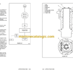
Excavator Machinery Plan .
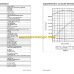
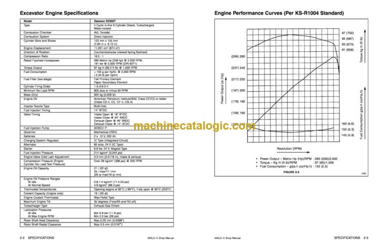
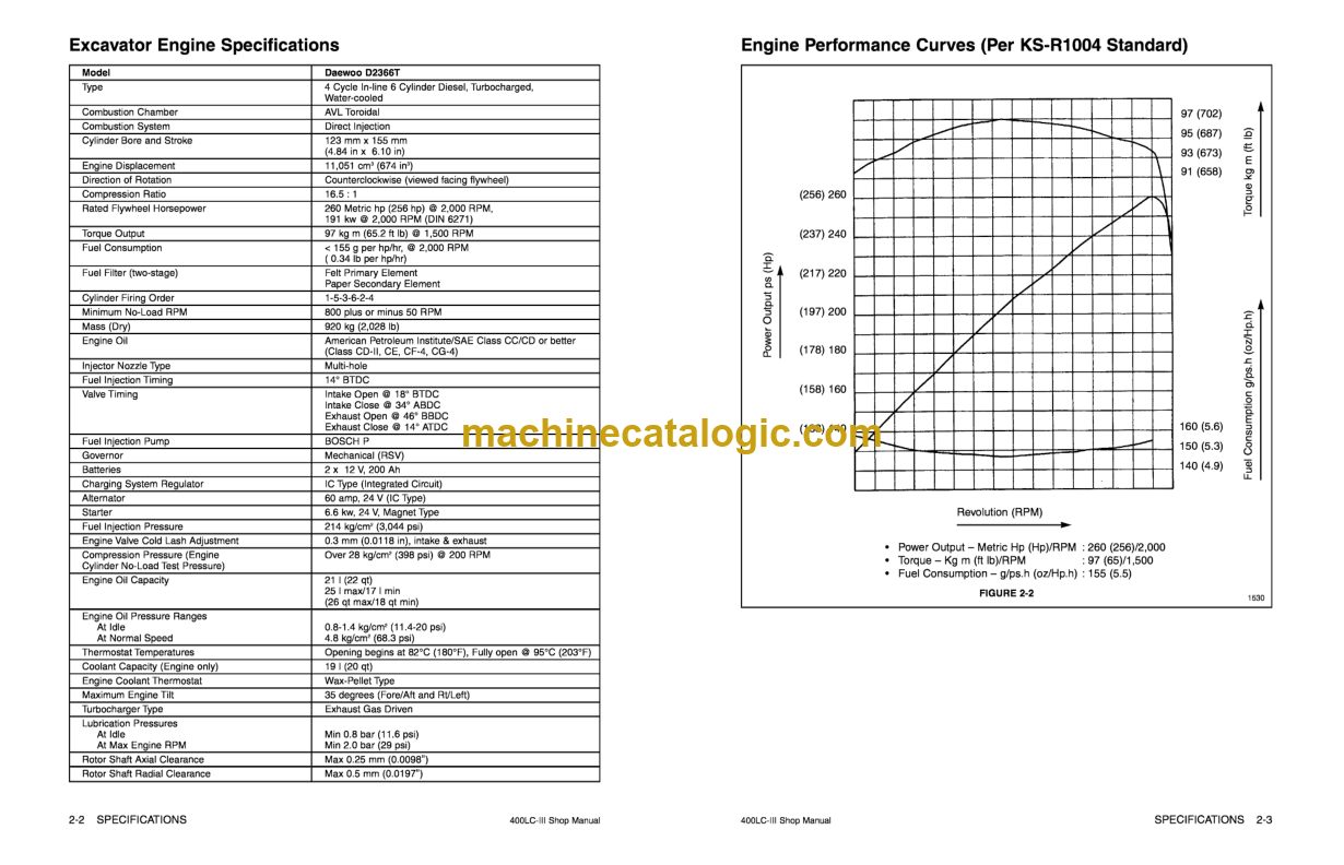
Excavator Engine Specifications
Engine Performance Curves (Per KS-R1004 Standard)
Hydraulic System Component Specifications
Hydraulic Pump Performance Characteristics
Specifications
General Dimensions
Working Range Dimensions ..
Reference Table — Approximate Weight of Workload Materials
Excavator Rated Lift Capacity Tables
UPPER STRUCTURE
Operator’s Cab Removal Procedure
Falling Object Protective Structures (F.O.2S.)
Front Attachment Pin Specifications .
Bucket Tooth Inspection and Replacement
Shimming Bucket Linkage
Bucket Attachment, Removal and Reversal
Removal and Installation of the Front Attachment
Attachment Cylinders, Disassembly and Reassembly
Cylinder Disassembly Special Tools
Operation of Hydraulic Cylinders
Cylinder Assembly and Disassembly
Cylinder Reassembly .
Welding Precautions and Guidelines
Accu mulator
Engine Components and Accessories
Counterweight Removal and Installation
Fuel Tank Removal and Installation
Engine Cooling System: Radiator/Oil Cooler
Swing Bearing Maintenance
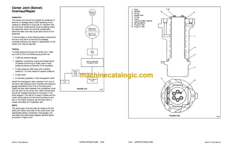
Center Joint (Swivel) Overhaul/Repair
Hydraulic System General Notes
Operation of Working Components
Main Pump Assembly Description
pump Regulator Description
Hydraulic System General Precautions
Maintenance Service and Repair Procedure
Troubleshooting — Main Pump
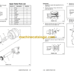
Main Pump Parts List
Main pump Disassembly and Reassembly
Reassembly of Main Pumps and Valve Block
Pump Regulator Parts List
Pump Regulator Disassembly and Reassembly
Swing Motor Basic Operation .
Rebuilding the Swing Motor — Disassembly
Swing Motor Parts List .
Rebuilding the Swing Motor — Assembly
Swing Gearbox — Disassembly
Swing Gearbox — Assembly
Control Valve Assembly
Pump Flow Control Regulator
Electronic Proportional Control Valve .
LOWER STRUCTURE
General Description .
Travel Motor — Theory of Operation
Travel Motor Brake
Counterbalance Valve
Relief Valve
Travel Motor Specifications
Travel Motor .
principles Of Torque Generation .
Two Speed Travel ….. ….. ….. .
Motor Rotation .
Motor Lubrication
Hydraulic Oil — Visual Inspection
Filter
Motor Installation and Inspection
Troubleshooting — Travel Motor
Troubleshootng — Travel Brake .
Troubleshooting — Relief Valve
Troubleshooting — Dual Counterbalance Valve
Troubleshooting —Two Speed Shift Valve
Travel Motor Repair Standards .
Rebuilding the Travel Motor — Disassembly (MAG-230-VP6000-3)
Travel Motor Assembly Torques
Rebuilding the Travel Motor — Assembly
Travel Gearbox – (Model RGC-230 .
Rebuilding the Travel Gearbox — Disassembly
Travel Gearbox Parts List
Rebuilding the Travel Gearbox — Assembly
Front Idler Roller Parts List
Lower Roller Parts List .
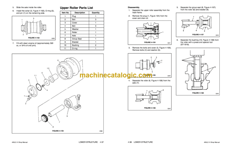
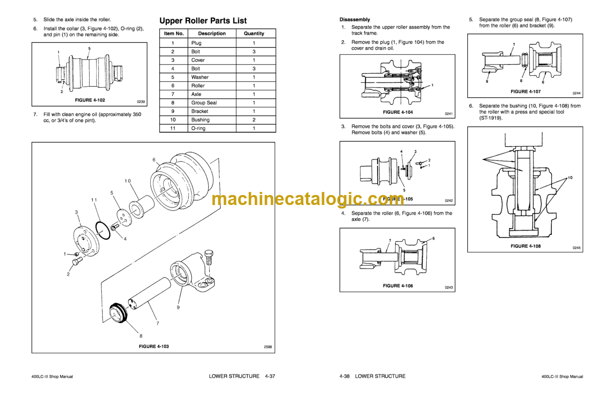
upper Roller Parts List .
Track Spring and Track Adjusting Cylinder parts List
Track Tensioning
Service Standards for Lower Travel Frame Components
ELECTRICAL SYSTEM
General Description
24 Volt Operation
Engine Start-up and Shutdown
Cylinder Preheat — Intake Air Electrical Heater .
Alternator Circuit
Low Current Electrical Circuits
Climate Control (Air Conditioning) Circuit .
Power Mode System Operating Components .
Instrument Panel
Instrument Panel LED Displays and Input Terminal Connections
Instrument Panel Connector Arrangement
Instrument Panel Selector Switches
Instrument Panel Coolant Overheating Circuit
Instrument Panel Indicator Lights
Instrument Panel Engine Oil Pressure Circuit
Start-up Electrical Test Circuit
Interior Lighting
Hydraulic Pump Discharge Pressure Sensor
Power Mode Circuit Instrument Panel Summary
Power Mode System Basic Operation
Power Mode Ill
Power Modell
Power Mode I
Swing Priority Circuit
Boom [Jp, Arm Crowd, and Bucket Crowd Combined Operation
Loading Work Mode
Swing and Arm Dump Combined Operation .
Swing Priority and Arm Crowd Recovery Function
Lifting Mode: Boom up and Arm Crowd Combined Operation .
Leveling Mode
Maintaining Straight Travel While Swinging .
Maintaining Straight Travel While Operating the Boom Arm, or Bucket Cylinders .
ENGINE
Engine Specifications (D2366T)
Wear Limits of Major Engine Components
Engine Oil Purnp Overhaul and Rebuilding
Fuel Injection Pump Installation, Alignment and Timing
Cylinder Headbolt Torque Requirements
Engine Throttle Controller
Engine Speed Sensor
INSPECTION, MAINTENANCE AND ADJUSTMENT
Periodic Inspection and Maintenance
Maintenance Intervals
Table of Recommended Lubricants
Inspection and Maintenance
Daily or Every IO Operating Hours .
Weekly or Every 50 Operating Hours
150 Operating Hours
Monthly or Every 250 Operating Hours
Three Months or Every 500 Operating Hours
Six Months or Every I ,OOO Operating Hours
Annually or Every 2,000 Operating Hours