Format: PDF (Printable Document)
File Language: English
File Pages: 1268
File Size: 29.47 MB (Speed Download Link)
Brand: Doosan (Daewoo)
Model: MT36, MT36 Series-2 Articulated Dump Truck
Serial No: Serial Number ——
Book No: MX159618-2
Type of Document: Shop Manual
$ 40
Chapter 00 – General Instructions
Contents
0-General Instructions
Foreword
Torque limit table
Metering conversion table
Types of sealing-/locking compounds and lubricants
Safety in workshop
Precautions for disassembly and assembly
Chapter 01 – Engine – 1 Structure and Function
Engine – 1-1 Structure and Function
Main Contents
Structure & Function – Contents
Cylinderblock
Pistons
Connecting rods
Crankshaft
Valve mechanism
Transmission
Cooling fan
Lubrication system
Turbocharger
Cooling system
Fuel system
Injectors and delivery pipes
Injection pump
Digital engine control (DEC2)
DEC2 components
Component location
Chapter 01 – Engine – 2 Testing and Adjusting
Engine – 1-2 Testing and Adjusting
Contents
Digital engine control (DEC2)
Start-up prosedure
Main menu
Tuning
Governor configuration
Valve clearance
Compression
Fuel system
Injectors
Injection pump
Cooling system
Chapter 01 – Engine – 3 Disassembly and Assembly
Engine – 1-3 Disassembly and Assembly
Contents
Removal of engine assembly
Engine identification
Cylinder head
Turbocharger
Pistons and cylinder liners
Flywheel and flywheel housing
Timing gear
Belt drive
Fuel system
Feed pump
Injectors
Injection pump
Lubrication system
Oil cleaner
Oil pump
Cooling system
Coolant pump
Thermostat
Fan drive
Charge air cooler
Oil cooler
Specifications
Special tools
Chapter 01 – Engine – 4 Maintenance Standard
Engine – 1-4 Maintenance Standard
Contents
Specifications
Cylinder head
Turbocharger
Pistons and cylinder liners
Connecting rods
Flywheel and flywheel housing
Crankshaft
Timing gear
Lubrication system
Cooling system
Chapter 01 – Engine – 5 Troubleshooting
Engine – 1-5 Troubleshooting
Contents
Digital engine control (DEC2)
Engine protection and Diagnostics
Fault finding
Fault finding procedure
Fault codes
Engine controller (DEC2) connecting table
Component specifications and circuit diagram DEC2
Connector identification and pin numbers
Component and connector placement on engine
Component and connector placement on cab
Troubleshooting tables
Chapter 02 – Transmission – 1 Structure and Function
Transmission – 2-1 Structure and Function
Main Contents
Structure & Function – Contents
Torque converter and transmission
Torque converter
Main relief valve
Torque converter valve (ECMV)
Transmission
Transmission valve ECMV
ECMV (Electronic control modulation valve)
High – Low and Diff lock solenoid valve
Hydraulic retarder valve
Hydraulic retarder drain valve
Automatic shift control system
Transmission controller
Shift lever switch
Sensors and switches
Chapter 02 – Transmission – 2 Testing and Adjusting
Transmission – 2-2 Testing and Adjusting
Contents
General information
Standard value table for r.p.m
Standard value table for hydraulic system
Standard value table for electrical system
Table of tools for testing, adjusting and troubleshooting
Testing oil pressure of transmission
Testing torque converter stall speed
Procedure for moving machine
Flushing procedure
Adjusting of transmission and engine speed sensors
Chapter 02 – Transmission – 3 Disassembly and Assembly
Transmission – 2-3 Disassembly and Assembly
Contents
Removal of transmission assembly
Disconnection of conv., transm., and transfer assembly
Connection of torque converter and transmission assembly
Disassembly of torque converter assembly
Assembly of torque converter assembly
Disassembly of PTO assembly
Assembly of PTO assembly
Disassembly of transmission assembly
Assembly of transmission assembly
Disassembly of transfer assembly
Assembly of transfer assembly
Transmission valve ECMV
Main relief valve
Chapter 02 – Transmission – 4 Maintenance Standard
Transmission – 2-4 Maintenance Standard
Contents
Torque converter
Transmission
Transfer
Main relief valve
Transmission valve ECMV
Hydraulic retarder valve
Hydraulic retarder drain valve
List of lubricants
Chapter 02 – Transmission – 5 Troubleshooting
Transmission – 2-5 Troubleshooting
Contents
Points to remember when troubleshooting
Sequence of events in troubleshooting
Points to remember when carrying out maintenance
Connector identification and pin numbers
Transmission controller connection table
Method of using judgement table
Method of using troubleshooting charts
Example: A-1 Abnormality in power source
Method of self diagnostic display for transmission controller
Action taken by self diagnostic device and problems on machine (transmission controller)
Troubleshooting of transmission controller system A mode
Troubleshooting of hydraulic and mechanical systems H mode
Chapter 03 – Drive Line – 0 General Instructions
Drive Line – 3-0 General Instructions
Main Contents
General Instructions – Contents
Overview Chapter 3
Foreword
Torque limits for screws
Chapter 03 – Drive Line – 1 Structure and Function
Drive Line – 3-1 Structure and Function
Contents
View of the drive line components
Front Reduction Gear cross section
Drive Shafts Front
Drive Shafts Rear
Front Diff and Transmission
Parking Brake
Main Brake
Rear Differential
Tandem Housing and Hub
Tyres
Chapter 03 – Drive Line – 2 Testing and Adjusting
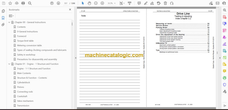
Drive Line – 3-2 Testing and Adjusting
Contents
Measuring oil levels
Service Brakes
Parking Brake
Drive line adjustment of the bearing
Differential TK
Tyre
Chapter 03 – Drive Line – 3 Disassembly and Assembly
Drive Line – 3-3 Disassembly and Assembly
Contents
Disassembly the wheel hub
List of special tool for the Planetary gear
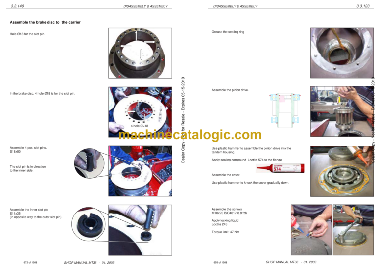
Disassembly & Assembly wheel hub
Disassemble the Transmission with front Differensial
Rear frame shaft and parking brake
The main brake
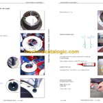
Change the bogie bearing
Assemble the tandem bearing
Tandem housing inside parts
Assemble the tandem housing inside parts
Disassembly the rear wheel hub
Assemble the wheel hub
Pre-assemble the axle housing
TK-differensial
Disassemble the TK-differential
Assemble the TK-diff in the axle housing
Chapter 03 – Drive Line – 4 Maintenance Standard
Drive line – 3-4 Maintenance Standard
Contents
Brakes
Tandem bearing limit of tolerance
Check the tandem housing bearing clearance
Check the articulation bearing clearance
Chapter 04 – Air System – 1 Structure and Function
Air system – 4-1 Structure and Function
Main Contents
Structure & Function – Contents
Brake circuit
Air circuit
Air supply
Air pressure system, front vehicle
Cabin air central system
Front brakes C1
Rear brake C2, front vehicle
Parking brake, C3
Parking brake, C3
Engine brake
Tilting system
Draining of air tanks
Air components
Chapter 04 – Air System – 2 Testing and Adjusting
Air system – 4-2 Testing and Adjusting
Contents
Standard values
Chapter 04 – Air System – 3 Disassembly and Assembly
Air system – 4-3 Disassembly and Assembly
Contents
Reconditioning of the compressor
Air dryer
Four-circuit protection valve
Relay valve
Main brake chamber
Parking brake air chamber
Parking brake servo valve
Quick release valve
Solenoid valve
Chapter 04 – Air System – 4 Maintenance Standard
Air system – 4-4 Maintenance Standard
Contents
Governor
Pressure reducing valve
Low pressure indicator
Brake light switch
Safety valve
Foot brake valve
Chapter 05 – Hydraulic System – 1 Structure and Function
Hydraulic system – 5-1 Structure and Function
Main Contents
Structure and Function – Contents
Hydraulic system
Hydraulic circuit function
Hydraulic tank
Hydraulic pump
Demand valve
Full flow filter
Steering system
Orbitrol
Steering valve
Steering cylinder
Emergency steering circuit
Emergency steering pump
Conecting valve
Flow indicator valve
Tip circuit
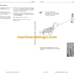
How the tip system works
Tip valve
Chock valve
Relief valve
Tip cylinder
Chapter 05 – Hydraulic System – 2 Testing and Adjusting
Hydraulic system – 5-2 Testing and Adjusting
Contents
Measurement of tip pressure
Adjustment of tip pressure
Standard values
Tipping system
Steering system
Oil and pump system
Chapter 05 – Hydraulic System – 3 Disassembly and Assembly
Hydraulic system – 5-3 Disassembly and Assembly
Contents
Fitting of swivel ends
Hydraulic dual pump
Demand valve
Emergency steering pump
Connecting valve
Flow indicator valve
Filter
Orbitrol valve
Steering valve
Steering cylinder
Tipping valve
Tipping cylinder
Chapter 06 – Electrical System – 1 Structure and Function
Description of el. system
General description
Welding on the dump truck
About DEC2
Battery hazard prevention
How to use the electrical documentation
Trouble shooting, what to do
Practical example
Description of circuit symbols
Specification of electrical components
Sensors on engine
Sensors on transmission
Sensors on Air system
Sensors on Hydraulic system
Where to find the position number on the machine:
Cross reference list
Map
Map 01 El.system, starting and charging
Map 02 El.system, front frame
Map 03 El.system, rear frame
Map 04 El.system, engine
Map 05 El.system, Sensors on engine
Map 06 El.system, Sensors on transmission
Map 07 El.system, cab
Map 08 Fuse box and relays
Map 09 Heater unit
Map 10 El.system, instrument and switch panel
Map 11 Components
Circuits
Circuit 01 Cab light
Circuit 02 Power supply / start
Circuit 03 Brake light
Circuit 04 Worklight / extra high beam
Circuit 05 Heated mirror / heated seat
Circuit 06 Central lubrication
Circuit 07 Enginecompartment light
Circuit 08 Worklight roof, backwards
Circuit 09 Reverse light
Circuit 10 Emergency steering
Circuit 11 Lighter
Circuit 12 Rotating beacon
Circuit 13 Radio
Circuit 14 Wiper, washer and horn
Circuit 15 Worklight on fenders, rear
Circuit 16 Direction and hazard light
Circuit 17 Hydraulic filter indicator
Circuit 18 Tilt wiring diagram and electrical
Circuit 19 Head light
Circuit 20 Gauge and instrument light
Circuit 21 Brake warning
Circuit 22 Engine wiring diagram
Circuit 23 Transmission wiring diagram
Circuit 24 Fan and Air condition
Chapter 07 – Front Chassis – 1 Structure and Function
Front frame – 7.1, structure and function
Main Contents
Structure and Function – Contents
Front Frame
Front axle Suspension
Welding on the front frame.
Bonnet
Radiator and fan system
Articulation hinge
Cab
Air condition
Chapter 07 – Front Chassis – 2 Testing and Adjusting
Front frame – 7.2, testing and adjusting
Contents
Bonnet locking system
Front axle suspension
Air condition
Chapter 07 – Front Chassis – 3 Disassembly and Assembly
Front frame – 7.3, disassembly and assembly
Contents
Front axle Suspension
Air condition
Bonnet
Radiator
Cab
Fenders, Mudguards and Tanks
Replacement of the articulation bearing
Assemble the articulation bearing
Chapter 07 – Front Chassis – 4 Maintenance Standard
Front frame – 7.4, maintenance standard
Contents
Front axle suspension
Check the articulation bearing clearance
Articulation hinge
Articulation hinge bearing limit of tolerance
Chapter 08 – Rear Chassis – 1 Structure and Function
Chapter 08 – Rear Chassis – 2 Testing and Adjusting
Rear frame – 8.2, testing and adjusting
Contents
Body
Chapter 08 – Rear Chassis – 3 Disassembly and Assembly
Rear frame – 8.3, disassembly and assembly
Contents
Rear frame
Welding on the rear frame
Body
Chapter 08 – Rear Chassis – 4 Maintenance Standard
Rear frame – 8.4, maintenance standard
Contents
Body general tolerance
Frame general tolerance
Chapter 09 – Option – 1 Structure and Function
Option – other equipment – 9.1, structure and function
Main contents
Structure and function – Contents
Central lubrication
Exhaust-heating for dump body
Engine heater
Top tail gate
Chapter 09 – Option – 2 Testing and Adjusting
Option – other equipment – 9.2, testing and adjusting
Contents
Central lubrication
Chapter 09 – Option – 3 Disassembly and Assembly
Option – other equipment – 9.3, disassembly and assembly
Contents
Central Lubrication
Exhaust-heating for dump body
Engine heater
Top tail gate
Chapter 09 – Option – 4 Maintenance Standard
Option – other equipment – 9.4, maintenance standard
Contents
Central lubrication
Engine heater
Chapter 09 – Option – 5 Troubleshooting
Option – other equipment – 9.5, troubleshooting
Contents
Central lubrication
Engine heater