Format: PDF (Printable Document)
File Language: English
File Pages: 1286
File Size: 34.06 MB (Speed Download Link)
Brand: Doosan (Daewoo)
Model: MT40B, MT40B Series-2 Articulated Dump Truck
Serial No: Serial Number 513002 and Up
Book No: MX159546-2
Type of Document: Shop Manual
$ 40
Chapter 00 – General Instructions
Contents
0-General Instructions
Chapter 01 – Engine – 1 Structure and Function
Engine – 1-1 Structure and Function
Contents
Cylinder block
Pistons
Connecting rods
Crankshaft
Crankshaft damper
Valve mechanism
Transmission
Lubrication system
Turbocharger
Charge air cooling
Scania Digital Engine Control system (DEC2)
Control unit
LED functions during normal operation
Sensors
Sensor location
Chapter 01 – Engine – 2 Testing and Adjusting
Engine – 1-2 Testing & Adjusting
Contents
Valve clearances
Injection pump – 7100 RE30
Feed pump pressure
Overflow valve
Testing in a nozzle tester
Digital engine control unit (DEC2)
Tuning
Governor Configuration
Governor calibration
Integrity testing of cooling system
Chapter 01 – Engine – 3 Disassembly and Assembly
Engine – 1-3 Disassembly & Assembly
Contents
Removal of engine ass’y
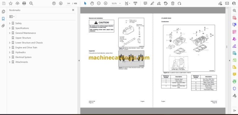
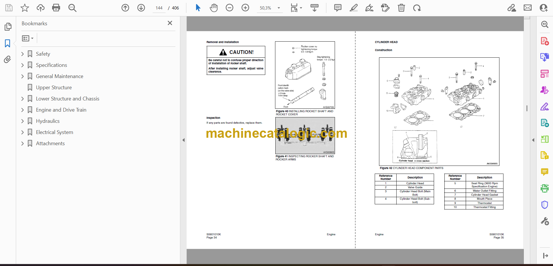
Cylinder head
Special tools
Removal of cylinder head
Checking, changing and machining
Turbocharger
Pistons and cylinder liners
Special tools
Flywheel and flywheel housing
Special tools
Timing gear cover
Timing gear
Special tools
Lubrication system
Oil pump
Charge air cooler
Fuel system
Coolant pump
Thermostat
Fan drive
Oil cooler
Specifications
Chapter 01 – Engine – 5 Troubleshooting
Engine – 1-5 Troubleshooting
Contents
White smoke
White smoke, water vapour
Black smoke when running/under load
Black smoke on starting
Blue smoke
Fuel in the oil
Fuel in oil, cont.
Oil in coolant
Coolant/water in oil
Coolant/water in oil, cont.
Low oil pressure
Low oil pressure, cont.
Low oil pressure, cont.
High oil pressure (engine warmed up)
High oil pressure (engine warmed up), cont.
Abnormal wear (liner, piston rings etc.)
Vibration, no driven components engaged
Delivery pipe fractures
External corrosion on cylinder liner
Engine difficult to start
Engine difficult to start, cont.
Fluid stroke
Fluid stroke, cont.
Knocking/noise
Knocking/noise, cont.
High oil consumption
High fuel consumption
Low compression
Low engine output
Low engine output, cont.
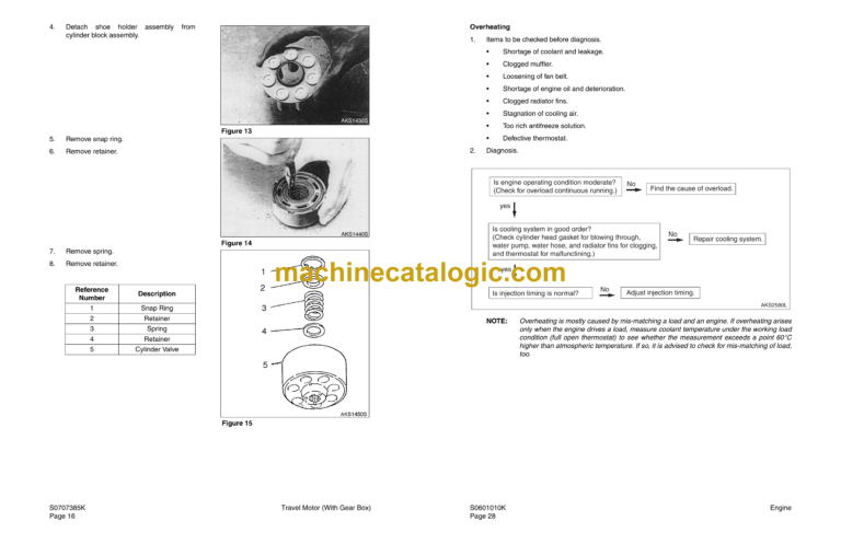
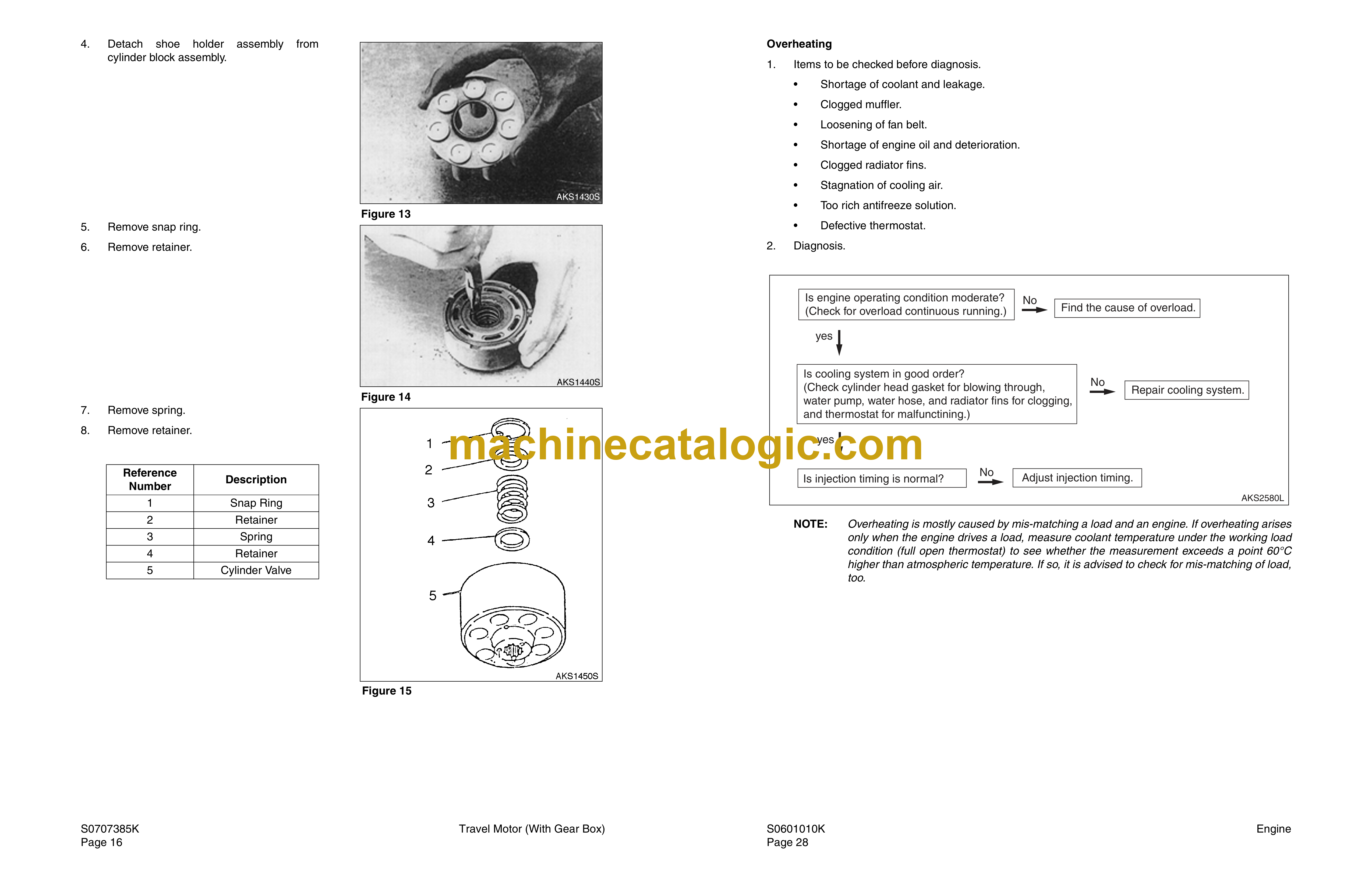
Hot engine
Hot engine, cont.
Cold engine
Coolant loss
Coolant loss, cont.
Polluted coolant
Engine heater
High oil temperature
High exhaust temperature
Low charge air pressure
Low fuel pressure
Low system voltage
High system voltage
External oil leakage
External oil leakage, cont.
External fuel leakage
External coolant leakage
External coolant leakage, cont.
Oil pressed oit via crankase ventilation
Torbocharger breakdown
Compressed air system
Fault finding – Digital engine control (DEC2)
FAULT CODES – DEC2
Chapter 02 – Transmission – 1 Structure and Function
Transmission – 2.1 Structure and Function
Contents
TECHNICAL DATA
Transmission cross section
IMPORTANT INSTRUCTIONS
DESCRIPTION
Powershift transmission
Retarder
Controller
Display
Electronic Control unit EST-37
AEB starter
Interaxle differential
OPERATION
Electro hydraulic shift control
Lubricant class
Chapter 02 – Transmission – 2 Testing and Adjusting
Transmission – 2-2 Testing and Adjusting
Contents
Testman
Testing system, ZF
Diagnostic – set
Installation
Start of Testman
Produkt menue Ergopower
A.E.B. Starter
Controller
Installation view
Measuring points and connections
Oil circuit diagram
Chapter 02 – Transmission – 3 Disassembly and Assembly
Transmission – 2-3 Disassembly and Assembly
Contents
GENERAL
List of special tool
View of the Special tool
Removal of cab, ass’y
Removal of transmission, ass’y
Electro-hydraulic control unit HSG-94
WK-Valve
Retarder
Manual transmission
Differential Carrier „LK“
Important when final assembly the Transmission
Chapter 02 – Transmission – 4 Maintenance Standard
Transmission – 2-4 Maintenance Standard
Contents
Testing systems
Oil grade
Axle insert „LK“
Transmission
Inductive transmitters and speed sensor
Sketch of the clutch
Chapter 02 – Transmission – 5 Troubleshooting
Transmission – 2-5 Troubleshooting
Contents
Prerequisites for the troubleshooting
Lay out 6WG-310
Installation view 6WG-310
Introduction
Testing system
Definition of operating modes
Table of fault codes
Controller
Transmission control unit (TCU)
Inductive transmitter
Electrohydraulic control with proportional valves
Oil circuit diagram
Chapter 03 – Drive Line – 1 Structure and Function
Drive line – 3-1 Structure and Function
Contents
General
Torque limits for screws
List of special tool for the Planetary gear
View of the drive line components
Front reduction gear cross section
Drive shafts front
Drive shafts rear
Front diff and transmission
Parking brake
Main brake
Rear differensial
Tandem housing
Tyres
Chapter 03 – Drive Line – 2 Testing and Adjusting
Drive line – 3-2 Testing and Adjusting
Contents
Measuring oil levels
Service brakes
Parking brake
Drive line adjustment of the bearing
Differential TK
Tyre
Chapter 03 – Drive Line – 3 Disassembly and Assembly
Drive line – 3-3 Disassembly and Assembly
Contents
Disassembly the wheel hub
Disassembly & Assembly
Disassembly the Transmission with front differensial
Rear frame shaft and parking brake
Exploded view of the tandem housing
Change the boggi bearing
Assemble the tandem bearing
Disassembly the wheel hub
Assemble the wheel hub
Disassemble the tandem housing’s innside parts
Assemble boggi innside parts
TK-differensial
Disassemble the TK-differential
Assemble the TK-diff in the axle housing
Chapter 03 – Drive Line – 4 Maintenance Standard
Drive line – 3-4 Maintenance Standard
Contents
Brakes
Tandem bearing limit of tolerance
Chapter 04 – Air System – 1 Structure and Function
Air system – 4-1 Structure and Function
Main Contents
Structure & Function – Contents
Air circuit diagram MT40B
Air circuit diagram MT40B Coal Hauler
Overview for the air components
Air supply
Air pressure system, front vehicle
Front brakes C1
Rear brake C2, front vehicle
Rear vehicle brake MT40B, C2
Rear vehicle brake MT40B – Ch, C2
Parking brake, C3
Retarder brake
Tilting system
Draining for air tanks
Pneumatic locking system rear-hatch MT40B CH
Air components
Chapter 04 – Air System – 2 Testing and Adjusting
Air system – 4-2 Testing and Adjusting
Contents
Standard values
Chapter 04 – Air System – 3 Disassembly and Assembly
Air system – 4-3 Disassembly and Assembly
Contents
Air dryer
Governor
Four-circuit protection valve
Foot brake valve
Relay valve
Main brake chamber
Parking brake air chamber
Quick release valve
Solenoid valve
Chapter 04 – Air System – 4 Maintenance Standard
Air system – 4-4 Maintenance Standard
Contents
Governor
Pressure reducing valve
Low pressure indicator
Retarder maneuvre valve
Safety valve
Chapter 05 – Hydraulic System – 1 Structure and Function
Hydraulic System – 5-1 Structure and Function
Contents
Hydraulic system
Hydraulic circuit function
Hydraulic tank
Hydraulic pump (double pump)
Demand valve
Full flow filter
Steering system
Orbitrol
Steering valve
Steering cylinder
Emergency steering circuit
Emergency steering pump
Conecting valve
Flow indicator valve
Tip circuit
How the tip system works
Tip valve
Chock valve
Relief valve
Tip cylinder
Chapter 05 – Hydraulic System – 2 Testing and Adjusting
Hydraulic System 5-2 Testing and Adjusting
Contents
Measurement of tip pressure
Adjustment of tip pressure
Standard values
Tipping system
Steering system
Oil and pump system
Chapter 05 – Hydraulic System – 3 Disassembly and Assembly
Hydraulic System – 5-3 Disassembly and Assembly
Contents
Fitting of swivel ends
Hydraulic dual pump
Demand valve
Emergency steering pump
Connecting valve
Flow indicator valve
Filter
Orbitrol valve
Steering valve
Steering cylinder
Tipping valve
Tipping cylinder
Chapter 06 – Electrical System – 1 Structure and Function
Electrical system – 6-1 Structure and Function
Contents
Description of el. system
Cross reference list
Map
Circuit
Location of transmitters
Chapter 07 – Front Chassis – 1 Structure and Function
Front frame – 7.1, structure and function
Main Contents
Structure & Function – Contents
Front Frame
Front axle Suspension
Welding on the front frame
Bonnet
Radiator and fan system
Articulation hinge
Cab
Air condition
Central lubrication
Chapter 07 – Front Chassis – 2 Testing and Adjusting
Front frame – 7.2, testing and adjusting
Front axle suspension
Air condition
Chapter 07 – Front Chassis – 3 Disassembly and Assembly
Front frame – 7.3, disassembly and assembly
Front axle suspension
Air condition
Bonnet
Radiator
Cab
Fenders, mudguards and tanks
Replacement of the articulation bearing
Assemble the articulation bearing
Chapter 07 – Front Chassis – 4 Maintenance Standard
Front frame – 7.4, Maintenance Standard
Front axle suspension
Check the articulation bearing clearance
Articulation hinge
Articulation hinge bearing limit of tolerance
Chapter 08 – Rear Chassis – 1 Structure and Function
Rear frame – 8.1, structure and function
Contents
View of the main parts , rear wagon
Rear frame, lifting points
Towing
Chapter 08 – Rear Chassis – 2 Testing and Adjusting
Rear frame – 8.2, testing and adjusting
Contents
Body
Chapter 08 – Rear Chassis – 3 Disassembly and Assembly
Rear frame – 8.3, disassembly and assembly
Contents
Rear frame
Body
Chapter 08 – Rear Chassis – 4 Maintenance Standard
Rear frame – 8.4, Maintenance Standard
Contents
Body general tolerance
Frame general tolerance
Chapter 09 – Option – 1 Structure and Function
Option – other equipment – 9.1, structure and function
Contents
Central lubrication
Exhaust-heating for dump body
Engine heater
Top tail gate
Chapter 09 – Option – 2 Testing and Adjusting
Option – other equipment – 9-2, testing and adjusting
Contents
Central lubrication
Chapter 09 – Option – 3 Disassembly and Assembly
Option – other equipment – 9-3. disassembly and assembly
Contents
Central Lubrication
Exhaust-heating for dump body
Engine heater
Top tail gate
Chapter 09 – Option – 4 Maintenance Standard
Option – other equipment – 9-4, maintenance standard
Contents
Central lubrication
Engine heater
Chapter 09 – Option – 5 Troubleshooting
Option – other equipment – 9-5, troubleshooting
Contents
Central lubrication
Engine heater