Format: PDF (Printable Document)
File Language: English
File Pages: 1084
File Size: 56.61 MB (Speed Download Link)
Brand: Doosan (Daewoo)
Model: MT41 Articulated Dump Truck
Serial No: Serial Number ——
Book No: MX512019-2
Type of Document: Shop Manual
$ 40
Chapter 00 – General Instructions
Main Contents
Index – chapter 0
Foreword
Torque limit table
Types of sealing-/locking compounds and lubricants
Safety in workshop
Vibration
Injurious noise
Organic solvent
Coolant
Refrigerant
Air pollution
Liquid or gas under high pressure
Fire and explosion risks
Asbestos
Jacked up vehicle or bodywork
Heavy units
More than one person working with the same object
Rotating parts
Splinters, .ying object When using certain tools
Springs under load
Precautions for disassembly and assembly
Chapter 01 – Engine
Removal of engine assembly
Lifting the engine
Engine identification
Fuel system
Schematic diagram of the fuel system
Overflow valve
General
FUEL
Fuel filter
Water separating prefilter
Feed pump
Diagnostic prosedure
Use of diagnostic kit, machine 810001 – 810052
Use of diagnostic kit, machine 810053 –
Measurement
Ecom standard settings code
Engine control unit, ECU
Wiring and cable duct
Throttle position sensor
Positions of sensors for ECU
Diagnostic lamp and switch (810001 – 810035)
Diagnostic lamp and switch (810036 – )
Fault codes
How to read fault codes from the ECU control unit
Flash codes tables
Overview of flash codes for coordinator
Renewing the control unit
Removing the ECU wiring
Cylinder head
Special tools
Cylinder head, parts view.
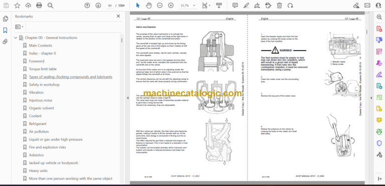
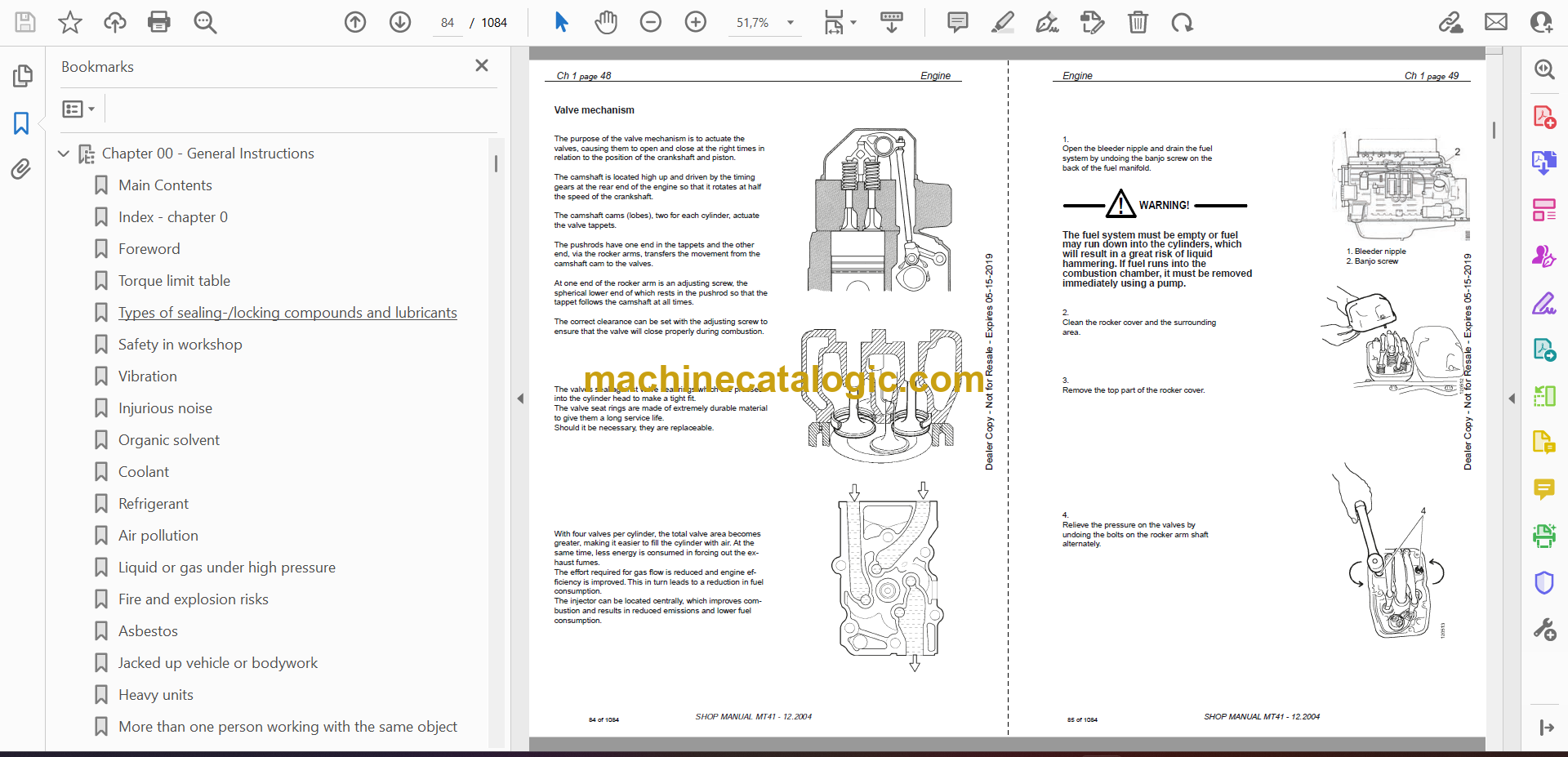
Valve mechanism
Dismantling
Renewing the valve stem seal
Replacement of valve seats
Machining the valve seats insert
Renewing the valve guides
Renewing PDE unit injector sleeves
Assembly
Fitting
PDE Injectors
Fitting the PDE injector
Adjusting unit injectors
Adjusting the valve clearance and unit injectors
Checking, adjusting the PDE injector rocker arms
Turbocharger
General
Special tools
Measuring radial clearance and axial clearance
Renewing the turbocharger
Pistons and cylinder liners
Special tools
Connecting rods
Removing and dismantling connecting rods and pistons
Renewal of bearing bushing in connecting rod
Pistons
Assembling piston and connecting rod
Cylinderblock
Cylinder liner
Removing the cylinder liners
Measuring the cylinder liner height
Fitting the cylinder liners
Fitting the piston and connecting rod
Flywheel and flywheel housing
Special tools
Removing the flywheel
Renewing the rear crankshaft seal
Removing the flywheel housing
Fitting flywheel housing
Fitting the flywheel
Timing gears
Gear drive
Belt drive collant pump, generator and AC compressor
Renewing the seal in the front cover
Crankshaft damper
Timing gear, view exploded
Special tools
Intermediate gear
Camshaft gear
Crankshaft gear
Camshaft
Replacement of camshaft bearing
Crankshaft
Removal
Fitting
Lubrication system
Oil pump
Lubrication oilways
Oil pressure
Oil cooler, engine
Oil cooler view
Renewing seals
Oil filter
Centrifugal oil cleaner
Dismantling and assembly
Cooling fan
Cooling system
View of the cooling system
Circulation
View of the radiator system
Disassemble the cooling unit
Thermostat and thermostat housing
Thermostat
Coolant pump
External cleaning
Internal cleaning
Specifications
General information
Electrical system
Cylinder head
Turbocharger
Pistons and cylinder liners
Connecting rods
Flywheel and flywheel housing
Timing gear
Lubrication system
Troubleshooting tables
White smoke
White smoke, water vapour
Black smoke when running/under load
Black smoke on starting
Blue smoke
Fuel in the oil
Oil in coolant
Coolant/water in oil
Low oil pressure
High oil pressure (Engine warmed up)
Abnormal wear (liner, piston rings, etc.)
Vibration, no driven components engaged
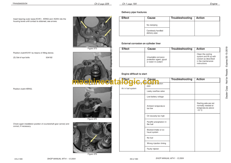
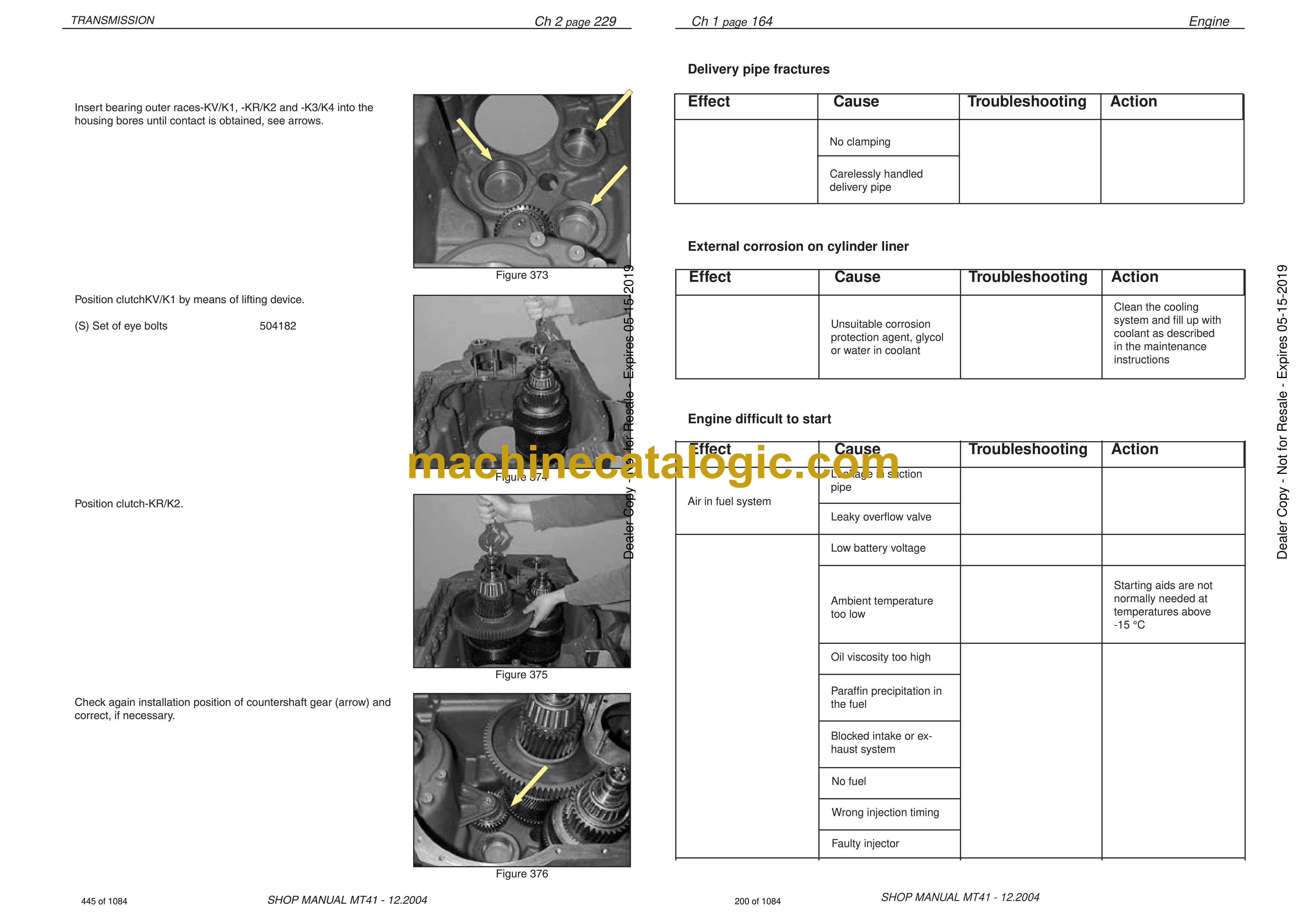
Delivery pipe fractures
External corrosion on cylinder liner
Engine difficult to start
Fluid stroke
Knocking noise
High oil consumption
High fuel consumption
Low compression
Low engine output
Hot engine
Cold engine
Coolant loss
Polluted coolant
Engine heater
High oil temperature
High exhaust temperature
Low charge air pressure
Low fuel pressure
Low system voltage
High system voltage
External oil leakage
External fuel leakage
External coolant leakage
Oil pressed out via crankcase ventilation
Turbocharger breakdown
Chapter 02 – Transmission Page 1-146
Chapter 2 Transmission.pdf
Chapter 02 – Transmission Page 147-310
Chapter 2 Transmission.pdf
Chapter 03 – Drive Line
Introduction
General
Structure of the Repair Manual
Important information on industrial safety
Denomination of standard dimensions
Conversion table
Torque limits for screws.
Table
View of the drive line components
Front reduction gear
View of the reduction gear and parts list
Front reduction gear cross section
Tool for RP17.
Disassembly the front wheel hub
Safety precautions.
Prepare Disassembly front wheel hub, RP-17
Disassembly
Assembly
Drive shafts
Front frame
Rear frame
The intermediate shaft
Front differential and transmission
Brakes
Service brakes
Service brake description
Testing of parking brake
Remove the Linings
Disassembly the park brake unit
Assembly the park brake unit.
Adjust the Initial Caliper Clearance
Park brake Maintenance
Disc
Troubleshooting Park brake
Rear differential
General function
Illustrated tables – Special tools
Disassemble the TK-differential
Safety precautions.
Disassemble the differentilal from the axle housing
Disassemble the boggi unit from frame
Dismantle Differential
Disassemble Drive pinion
ASSEMBLY
Adjust Backlash
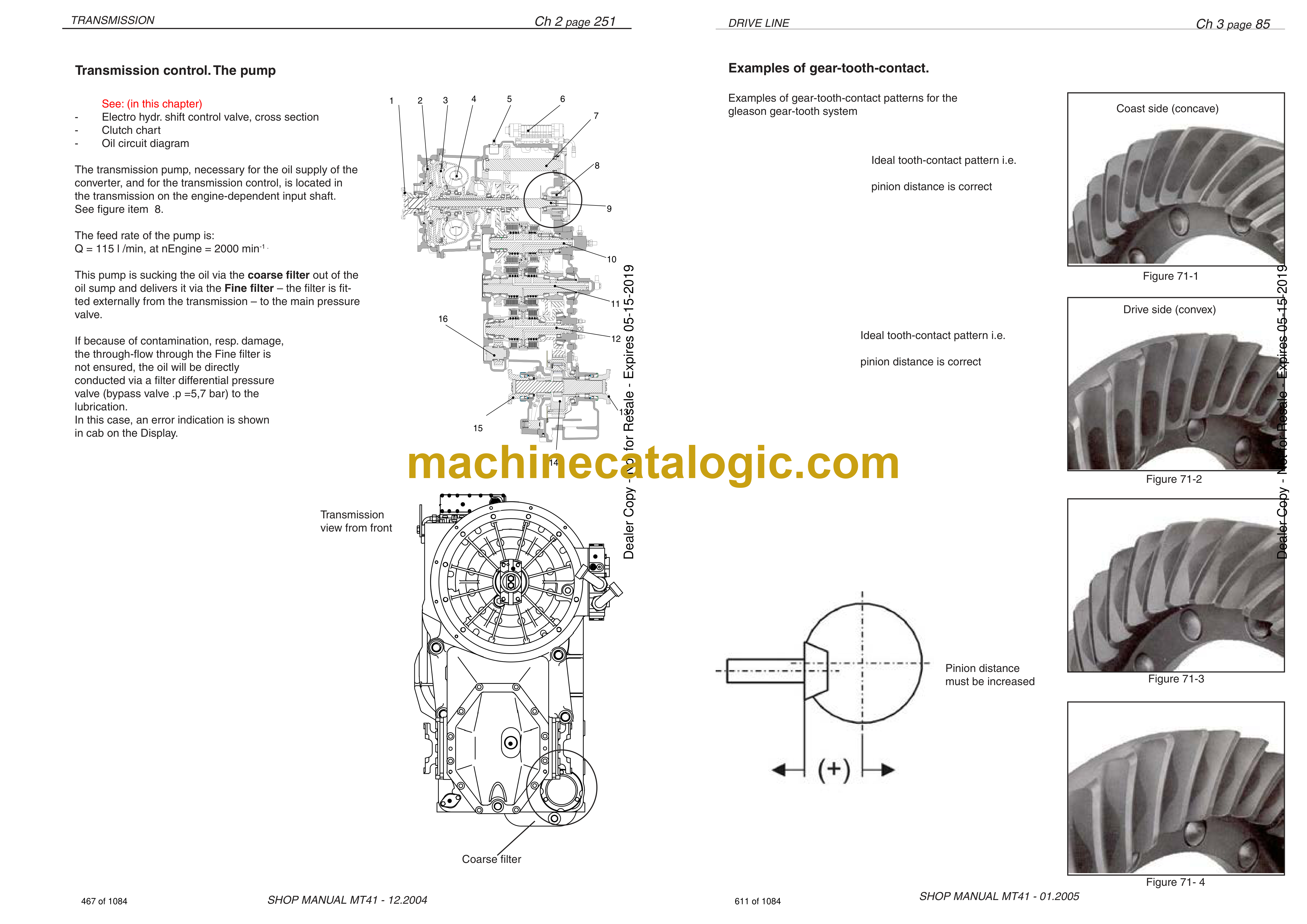
Examples of gear-tooth-contact.
Assemble the TK-diff in the axle housing
Assemble the tandem housing unit to the rear frame.
Wet disc brake
Front hub
Outer view and section drawing
Tools for WDB
Disassembly the front wheel hub
Disassemble the WDB-brake housing
Reassemble
Adjust the rolling resistance of the wheel bearing
Installation of the wet multi-disc brake
Pre-assemble the return mecanism
Installation of the wheel head
Check the brake chamber/wheel head for leak tightness
Leakage test of the brake hydraulics
WDB cirquit front brake
Rear hub,
Outer view and section drawing
Disassembly the rear hub
Assemble the WDB rear hub
Cooling cirquit rear brake
Axle and Tandem housing Bearing
Cross section
Checking clearance in the Tandem bearing.
View of the Tandem bearing
Calculation of the Tandem bearing
Disassemble Tandem housing unit
Safety precautions.
Disassemble the tandem unit from the rear frame
Disassembly the axle housing from the tandemhousing
Disassemble the tandem bearings
Assemble the tandem housing to the axle housing
Wheel hub, rear
Safety precautions.
Sectional drawing of the wheel hub.
Disassembly the wheel hub
Assemble the wheel hub
Assemble the brake disc to the carrier
Pre-assembly the wheel hub axle
Pre-assembly the wheel hub
Assembly the wheel hub to the axle
Assemble the gear wheel to the hub
Assembly the hub to tandem housing
Disassemble the tandem housing’s innside parts
Assembly piniong in the tandem house
Tyres
Chapter 05 – Hydraulic System 810001-810052
Components, capacities and oil types
Startup test procedure
Main pump
Steering system
Tilting system
Fan system
Brakes
Accumulators
Chapter 05 – Hydraulic System 810053-
Components, capacities and oil types
Startup test procedure
Main pump
Steering system
Tilting system
Fan system
Brakes
Accumulators
Chapter 06 – Electrical system
Description of el. system
General description
Welding on the dump truck
Battery hazard prevention
How to use the electrical documentation
Faultfinding, what to do
Practical example
Description of circuit symbols
Electrical parts view
Spesification of electrical components.
General coordinator connection diagram 810001 – 810035
Coordinator description (Scania) page 1. 810001 – 810035
Coordinator description (Scania) page 2 810001 – 810035
Flashing code list for the EMS control unit.
General coordinator connection diagram 810036 –
Coordinator description (Scania) page 1. 810036 –
Coordinator description (Scania) page 2. 810036 –
Spesification of electrical components
CT1 introduction (from machine 810053 – )
CT1 Tecnical data
Position list.
List
Map
Map 01 El.system, outside front and rear
Map 02 El.system, Front frame
Map 03 El.system, Rear frame
Map 04 El.system, Sensors on Engine
Map 05 El.system, Sensors on Engine
Map 06 El.system, Sensors on Transmission
Map 07 El.system, Cab outside and ceiling
Map 08 Cab lower
Map 09 Fuse box and relays
Map 10 Heater unit
Map 11 El.system, Instrument panel
Map 12 Cab innside, lower panel
Circuits
Circuit 01 Compartment and cab light
Circuit 02 Brake light
Circuit 03 Power supply / start
Circuit 04 Work light / Extra high beam
Circuit 05 Heated mirrors
Circuit 06 Fan and A/C
Circuit 09 Rewerse and work light rear
Circuit 10 Gauge and Instrument light
Circuit 10 Gauge and Instrument light. 810053-
Circuit 11 Lighter
Circuit 12 Rotating beacon
Circuit 13 Radio
Circuit 14 Wiper, washer and horn
Cirquit 15 Seat belt warning
Cirquit 16 Heated chair and chair compressor
Cirquit 18 Engine serial no: 810001 – 810035
Cirquit 18 Engine serial no: 810036-810052
Cirquit 18 Engine serial no: 810053-
Cirquit 19 Transmission serial no. 810001-810052
Cirquit 19 Transmission serial no. 810053-
EST 37 pinout
IVC4B Connector pinout
Cirquit 20 Brake warning light 810001 – 810052
Cirquit 20-1 Brake warning light – WDB 810053-
Cirquit 20-2 WDB Brake monitoring 810053-
Cirquit 21 Head light
Cirquit 22 Tilt magnet (servo valve)
Cirquit 24 Direction and hazard light
Cirquit 25 Cooling fan
Cirquit 26 Emergency steering
Cirquit 27 Hydraulic oil filter
Cirquit 28 Central lubrication, Groeneveld
Cirquit 29 Central lubrication, Lincoln
Cirquit 30 Gear restriction
Chapter 07 – Front frame
Chapter 08 – Rear frame
Chapter 09 – Lincoln Quicklub User Manual
Title
Imprint
Table of Contents
Lincoln worldwide
Chapter 09 – Optional equipment
