Doosan N8000 Hydraulic Breaker Operation and Maintenance Manual (Serial Number X260A50000 and Up)
Doosan N8000 Hydraulic Breaker Table of Contents:
Foreword . . . . . . . . . . . . . . . . . . . . . . . . . . . . . . . . . . . . . . . . . . . . . . 5
Safety . . . . . . . . . . . . . . . . . . . . . . . . . . . . . . . . . . . . . . . . . . . . . . . . . 7
Identification And Machine Signs (Decals) . . . . . . . . . . . . . . . . 8
Unauthorized Modifications . . . . . . . . . . . . . . . . . . . . . . . . . . . . . 10
General Hazard Information . . . . . . . . . . . . . . . . . . . . . . . . . . . . 10
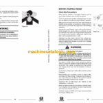
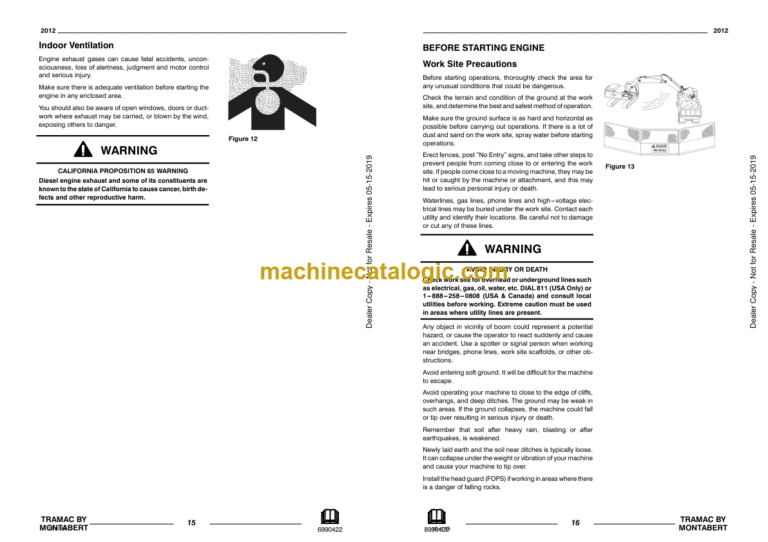
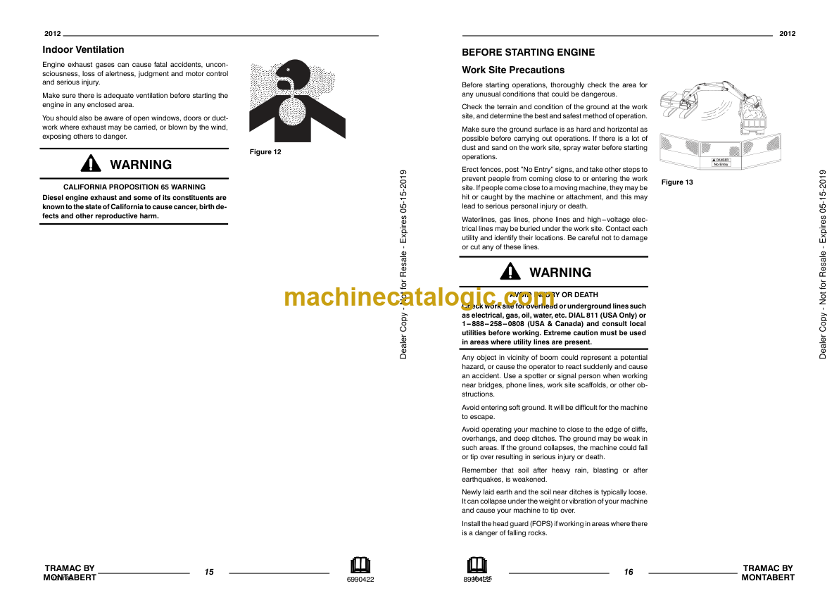
Before Starting Engine . . . . . . . . . . . . . . . . . . . . . . . . . . . . . . . . . 16
Machine Operation . . . . . . . . . . . . . . . . . . . . . . . . . . . . . . . . . . . . 17
Maintenance . . . . . . . . . . . . . . . . . . . . . . . . . . . . . . . . . . . . . . . . . 19
Serial Number Location . . . . . . . . . . . . . . . . . . . . . . . . . . . . . . . 24
Maintenance Points . . . . . . . . . . . . . . . . . . . . . . . . . . . . . . . . . . . 25
Lift Points And Weights . . . . . . . . . . . . . . . . . . . . . . . . . . . . . . . 27
Specifications . . . . . . . . . . . . . . . . . . . . . . . . . . . . . . . . . . . . . . . . 28
Auxiliary Circuit Oil Flow Calibration . . . . . . . . . . . . . . . . . . . 30
Tool Removal . . . . . . . . . . . . . . . . . . . . . . . . . . . . . . . . . . . . . . . . . 31
Tool Installation . . . . . . . . . . . . . . . . . . . . . . . . . . . . . . . . . . . . . . . 32
Inspection, Maintenance And Adjustment . . . . . . . . . . . . . . 33
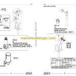
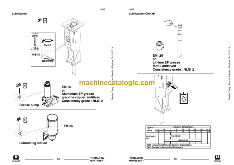
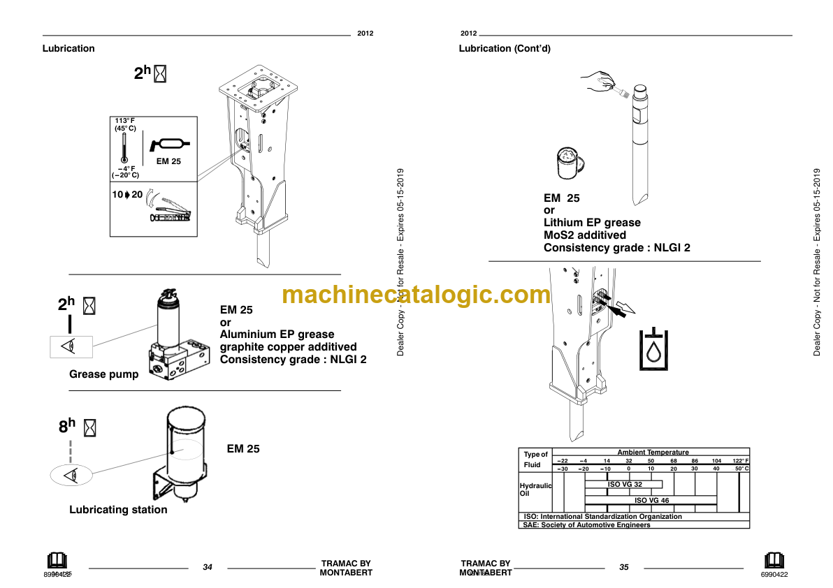
Lubrication . . . . . . . . . . . . . . . . . . . . . . . . . . . . . . . . . . . . . . . . . . . 34
Check Retaining Pin . . . . . . . . . . . . . . . . . . . . . . . . . . . . . . . . . . . 36
Check Tool Point . . . . . . . . . . . . . . . . . . . . . . . . . . . . . . . . . . . . . . 37
Measure Bushing Wear . . . . . . . . . . . . . . . . . . . . . . . . . . . . . . . . . 38
Approved Models And Requirements . . . . . . . . . . . . . . . . . . 39
Attachment Requirements and Precautions . . . . . . . . . . . . . . . 39
Operating Breaker . . . . . . . . . . . . . . . . . . . . . . . . . . . . . . . . . . . . 40
Working Position . . . . . . . . . . . . . . . . . . . . . . . . . . . . . . . . . . . . . . 40
Maximum Working Time . . . . . . . . . . . . . . . . . . . . . . . . . . . . . . . 41
Breaker Tool Position . . . . . . . . . . . . . . . . . . . . . . . . . . . . . . . . . . 41
Repositioning Material . . . . . . . . . . . . . . . . . . . . . . . . . . . . . . . . . 42
Operating Techniques . . . . . . . . . . . . . . . . . . . . . . . . . . . . . . . . . 43
Working Temperature . . . . . . . . . . . . . . . . . . . . . . . . . . . . . . . . . . 48
Lift And Transport . . . . . . . . . . . . . . . . . . . . . . . . . . . . . . . . . . . . . 49
Lifting the Attachment . . . . . . . . . . . . . . . . . . . . . . . . . . . . . . . . . . 49
Transporting . . . . . . . . . . . . . . . . . . . . . . . . . . . . . . . . . . . . . . . . . . 49
Impact Effect On Tool . . . . . . . . . . . . . . . . . . . . . . . . . . . . . . . . . 50
Charging Nitrogen Chamber . . . . . . . . . . . . . . . . . . . . . . . . . . . 52
Back Head Inflating Table . . . . . . . . . . . . . . . . . . . . . . . . . . . . . 62
Troubleshooting Guide . . . . . . . . . . . . . . . . . . . . . . . . . . . . . . . . 63
Short Term Storage . . . . . . . . . . . . . . . . . . . . . . . . . . . . . . . . . . . 66
Long Term Storage . . . . . . . . . . . . . . . . . . . . . . . . . . . . . . . . . . . . 67
Stroke Adjustment . . . . . . . . . . . . . . . . . . . . . . . . . . . . . . . . . . . . 68
INSTALLATION MANUAL
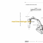
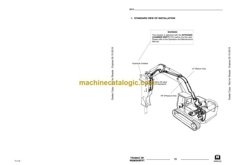
Standard View Of Installation . . . . . . . . . . . . . . . . . . . . . . . . . . 73
Connecting The Hydraulic Hoses . . . . . . . . . . . . . . . . . . . . . . 74
Flushing The Hydraulic Lines . . . . . . . . . . . . . . . . . . . . . . . . . . 75
Auxiliary Circuit Pressure Relief Valve Setting . . . . . . . . . . 76
Auxiliary Circuit Oil Flow Setting . . . . . . . . . . . . . . . . . . . . . . . 77
Auxiliary Circuit Oil Flow Checking . . . . . . . . . . . . . . . . . . . . . 78
Hydraulic Schematic . . . . . . . . . . . . . . . . . . . . . . . . . . . . . . . . . . 79
Fixing Cap Mounting . . . . . . . . . . . . . . . . . . . . . . . . . . . . . . . . . . 80
Checking For Interference . . . . . . . . . . . . . . . . . . . . . . . . . . . . . 81
Connecting The Hydraulic Hoses On Breaker . . . . . . . . . . . 82
Check The Hose Length . . . . . . . . . . . . . . . . . . . . . . . . . . . . . . . 83
Doosan


