Format: PDF
Language: EN
Size: 18.66 MB
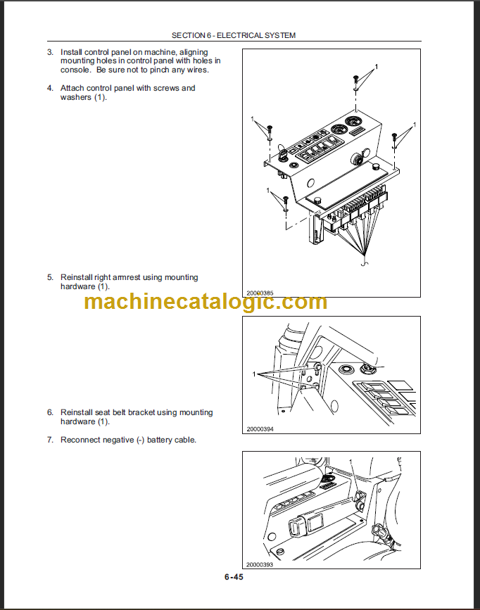
Pages: 415
Speed Download Link
$ 50 Original price was: $ 50.$ 40Current price is: $ 40.
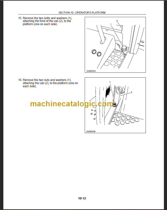
EC15-EC25-EC35-EC45 SERVICE MANUAL contains high quality images, diagrams, instructions to help you to operate, maintenance, diagnostic, and repair your machine. This document is printable, without restrictions, contains searchable text and bookmarks for easy navigation.
Table of Contents
General Information
Hydraulic System
Electrical System
General Electrical Information ………………………………………………………………………………………………. 6-8
Definition of Terms ………………………………………………………………………………………………………………. 6-9
Wire Abbreviations to Indicate Wire Color …………………………………………………………………………….. 6-10
Specifications …………………………………………………………………………………………………………………… 6-11
Instrument Panel Component Locations and Functions ………………………………………………………….. 6-12
Fuse Panel Component Locations and Functions ………………………………………………………………….. 6-13
Electrical Circuits ……………………………………………………………………………………………………………… 6-14
Power Supply Circuit ……………………………………………………………………………………………………… 6-14
Startup and Pre-Heat Circuit …………………………………………………………………………………………… 6-15
Travel Fast/Slow Circuit ………………………………………………………………………………………………….. 6-17
EC15 ………………………………………………………………………………………………………………………… 6-17
EC25/EC35 ……………………………………………………………………………………………………………….. 6-17
EC45 ………………………………………………………………………………………………………………………… 6-17
Alternator Charge Lamp & Operating Hourmeter Circuit ……………………………………………………… 6-18
Warning Buzzer Circuit …………………………………………………………………………………………………… 6-20
Oil Pressure Sensing Circuit …………………………………………………………………………………………… 6-20
Air Filter Restriction Indicator ………………………………………………………………………………………….. 6-20
Hydraulic Oil Filter Clogging Indicator Circuit …………………………………………………………………….. 6-20
Coolant Temperature Indicator Circuit ……………………………………………………………………………….. 6-20
Fuel Gauge Circuit …………………………………………………………………………………………………………. 6-22
Heater Fan Circuit ………………………………………………………………………………………………………….. 6-22
Washer/Wiper Circuit ……………………………………………………………………………………………………… 6-23
Working Flood Light Circuit ……………………………………………………………………………………………… 6-24
Rotating Beacon Circuit ………………………………………………………………………………………………….. 6-24
Radio Circuit …………………………………………………………………………………………………………………. 6-25
Internal Lights and Socket Circuit …………………………………………………………………………………….. 6-25
Horn Circuit ………………………………………………………………………………………………………………….. 6-26
Fuel Pump Circuit ………………………………………………………………………………………………………….. 6-26
Removal, Installation and Wiring of Electrical Components …………………………………………………….. 6-27
Battery …………………………………………………………………………………………………………………………. 6-27
EC15 ………………………………………………………………………………………………………………………… 6-27
Removal ………………………………………………………………………………………………………………… 6-27
Installation ………………………………………………………………………………………………………………. 6-27
EC25 and EC35 …………………………………………………………………………………………………………. 6-28
Removal ………………………………………………………………………………………………………………… 6-28
Installation ………………………………………………………………………………………………………………. 6-28
EC45 ………………………………………………………………………………………………………………………… 6-29
Removal ………………………………………………………………………………………………………………… 6-29
Installation ………………………………………………………………………………………………………………. 6-29
Fuses…………………………………………………………………………………………………………………………… 6-30
Fuse Panel Wiring ………………………………………………………………………………………………………. 6-30
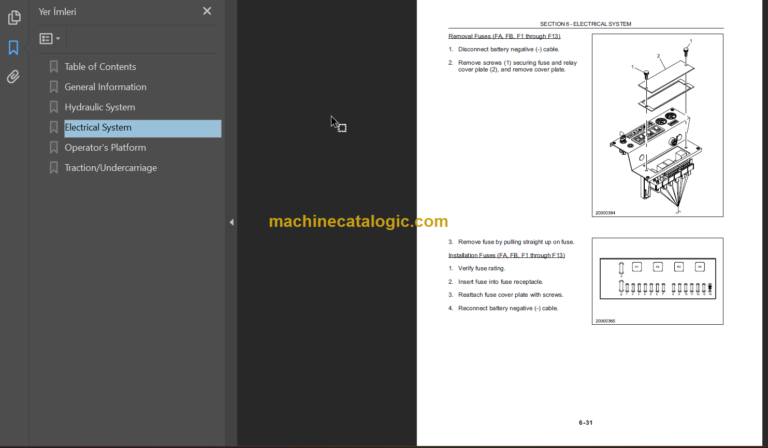
Removal (Fuses FA, FB, F1 through F13) ……………………………………………………………………… 6-31
Installation (Fuses FA, FB, F1 through F13) …………………………………………………………………… 6-31
Relays and Diode Block …………………………………………………………………………………………………. 6-32
Relay K1 …………………………………………………………………………………………………………………… 6-32
Diode Block K4 Wiring ………………………………………………………………………………………………… 6-32
Relay K1 Wiring………………………………………………………………………………………………………….. 6-32
Relay K10 Wiring ………………………………………………………………………………………………………… 6-33
Relays K1, K2, K3, K4 ………………………………………………………………………………………………… 6-34
Removal ………………………………………………………………………………………………………………… 6-34
Installation ………………………………………………………………………………………………………………. 6-34
Relay K10 Pre-Heat Timer Unit …………………………………………………………………………………….. 6-35
Removal ………………………………………………………………………………………………………………… 6-37
Installation ………………………………………………………………………………………………………………. 6-37
Pre-Heat/Start (Ignition) Switch ……………………………………………………………………………………. 6-38
Pre-Heat/Start (Ignition) Switch Wiring ……………………………………………………………………….. 6-38
Removal ………………………………………………………………………………………………………………… 6-39
Installation ………………………………………………………………………………………………………………. 6-40
Fan (Heater/Ventilator) Switch ……………………………………………………………………………………… 6-42
Fan Switch (S15) Wiring …………………………………………………………………………………………… 6-42
Removal ………………………………………………………………………………………………………………… 6-43
Installation ………………………………………………………………………………………………………………. 6-44
Washer/Wiper Switch ………………………………………………………………………………………………….. 6-46
Washer/Wiper Switch (S11) Wiring ……………………………………………………………………………. 6-46
Removal ………………………………………………………………………………………………………………… 6-47
Installation ………………………………………………………………………………………………………………. 6-48
Working Floodlight Switch ……………………………………………………………………………………………. 6-50
Working Floodlight Switch Wiring ………………………………………………………………………………. 6-50
Removal ………………………………………………………………………………………………………………… 6-51
Installation ………………………………………………………………………………………………………………. 6-52
Rotating Beacon Switch ………………………………………………………………………………………………. 6-54
Rotating Beacon Switch Wiring …………………………………………………………………………………. 6-54
Removal ………………………………………………………………………………………………………………… 6-55
Installation ………………………………………………………………………………………………………………. 6-56
Fast/Slow Switch ………………………………………………………………………………………………………… 6-58
Removal ………………………………………………………………………………………………………………… 6-58
Installation ………………………………………………………………………………………………………………. 6-59
Operators Platform
Traction/Undercarriage

