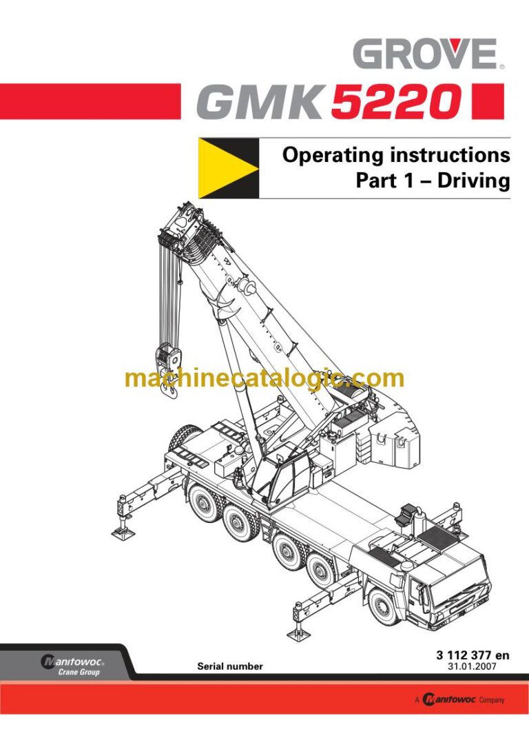
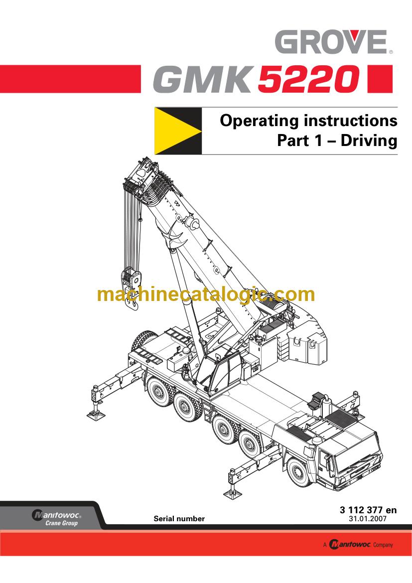
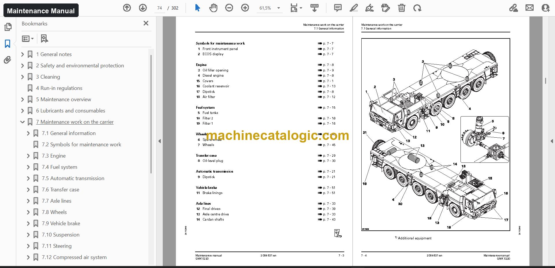
A GMK 5220 is a five-axle all terrain crane. It drives to site on public roads, then sets up and lifts with its telescopic boom. If you're taking on a used one that arrived without any paperwork, this set puts every document for that one model in a single download, so you're not chasing books one at a time.
What this manual set helps you do
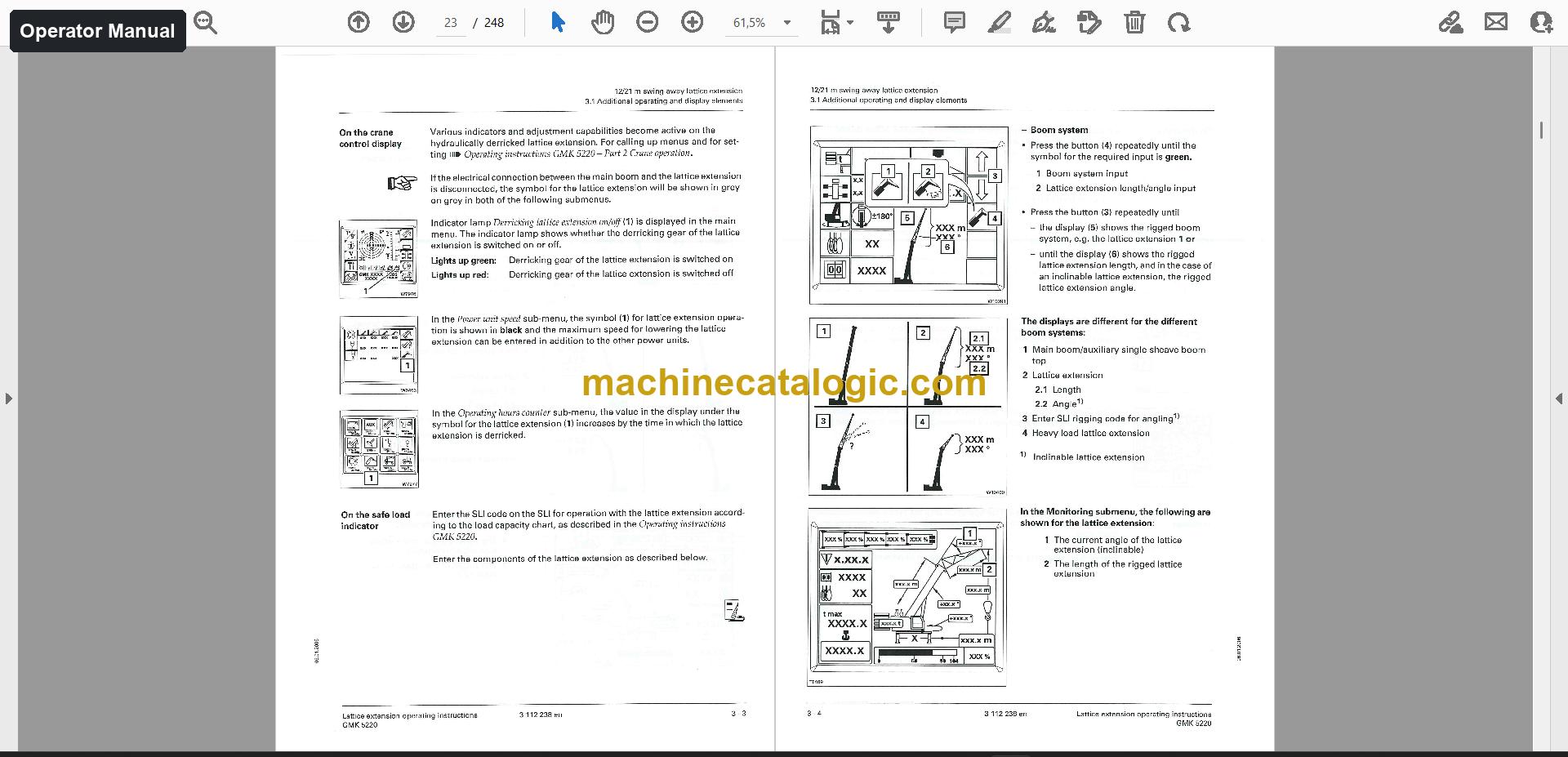
- Operate the crane and the swing-away lattice extension, with the rigging checklists and the description of rigging work from the operator manual.
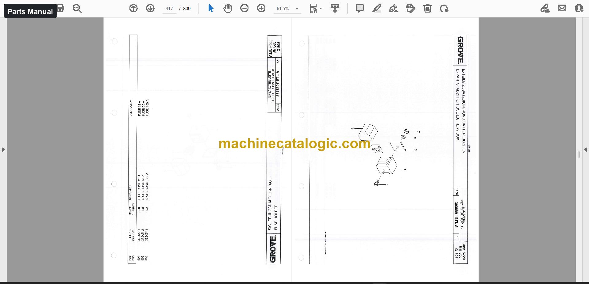
- Order the right parts using the spare parts catalogue, which has sections like chassis, drivers cab, engine covering and simplex brake.
- Follow service intervals, lubricants and consumables, and the maintenance work on the carrier and superstructure from the maintenance manual.
- Trace hydraulic and electrical circuits using the schematics, 9 files and 409 pages.
- Plan lifts with the load charts, 12 files, and check the diagnostic documents and ECOS ErrorCodeViewer installer when a fault shows up.
Who this is for
A workshop or service company that has just taken in a GMK 5220 and needs the maintenance routine, parts numbers and drawings before the first job. It also suits a rental fleet manager who wants operators, mechanics and the parts desk working from the same documents.
FAQ
Q: What do I receive and how is it organised?
A: You get 205 files, 61 of them PDF, 25,715 PDF pages in total. The operator manual is 5,472 pages in 10 files (English), the parts manual is 10,068 pages in 14 files (English and German), and the maintenance manual is 1,186 pages in 4 files (English). Schematics, load charts, technical data, training documents and software come alongside.
Q: Which machine does it fit?
A: It is made for the Grove GMK 5220 all terrain crane. The titles are GMK 5220 Operating Instructions, Lattice Extension Instructions, Spare Parts Catalogue and Maintenance Manual.
Q: How does it fit my job?
A: Whether you're servicing, ordering parts or rigging the lattice extension, the documents for each task sit in one download. You'd expect to find the daily and periodic work in the maintenance manual, the part identification in the parts catalogue, and the circuit drawings in the schematics.
Download the set, hand each person the manual for their task, and work from the same documents on every GMK 5220 job.
📘 Show Index
Table of Contents:
Operator Manual Table of Contents
5,472 pages, 10 files
- Cummins engine / Publication 3 112 322 en (1,166 pages)
- Important information
- About these operating instructions
- Basic safety instructions
- Intended use
- Transport dimensions and weights
- Swing-away lattice extension
- Auxiliary single-sheave boom top
- Heavy load lattice extension
- 12/21 m swing-away lattice extension
- Additional operating and display elements
- Identification of the swing-away lattice extension
- Composition of the swing-away lattice extension
- Boom extension
- Identification and slinging points
- Assembly of boom extensions
- Checklists for rigging work
- Auxiliary single-sheave boom top
- Identification
- Installing/removing auxiliary single-sheave boom top
- Rigging the auxiliary single-sheave boom top
- Heavy load lattice extension
- Identification
- Attaching and securing the heavy load lattice extension
- Installing/removing the heavy load lattice extension
- Publication 3 112 375 en / Serial No. 52202130 (878 pages)
- Overview
- Identification
- EC Declaration of Conformity
- Documentation supplied
- Basic safety instructions
- Intended use
- Organisational measures
- Personnel qualification
- Operating elements when driving
- Overview of the operating elements
- Short description of the operating elements
- Starting/turning off the engine for driving
- Starting the engine from the driver's cab
- Turning off the engine
- Air intake inhibitor
- Driving
- Before driving
- Operating the transmission
- Driving and turning off the truck crane
- Driving modes and rigging for on-road driving
- Driving modes
- Rigging work for driving with a trailer
- Rigging the main boom
- Malfunctions in driving mode
- Emergency stop devices
- What to do when a malfunction occurs in road traffic
- Towing the truck crane
- Technical information on the carrier
- Operating elements for crane operation
- Overview of the operating elements
- Short description of the operating elements
- Starting/turning off the engine – for crane operation
- Starting the engine – from the crane cab
- Starting the engine – with the hand-held control
- Turning off the engine
- Crane operation
- Before crane operation
- Operation of the safe load indicator
- Crane operation with main boom
- Rigging work
- Rigging work checklists for crane operation with the main boom
- Choosing a suitable site
- Rigging work after driving with a trailer
- Driving the rigged truck crane
- Route
- Permissible rigging modes and axle loads
- Before driving
- Malfunctions during crane operation
- Emergency stop devices
- What to do when a malfunction occurs during crane operation
- Fuses on the superstructure
- Technical information for the superstructure
- Publication 3 112 629 en / Serial No. 5220 2315 (1,150 pages)
- 12/21 m swing-away lattice extension
- Additional operating and display elements
- In the crane cab
- Operating and display elements on the hand-held control
- Operating and display instruments on the swing-away lattice extension
- Identification of the swing-away lattice extension
- Composition of the swing-away lattice extension
- Centres of gravity for slinging
- Checklists for rigging work
- Overview of the required rigging work
- CHECKLIST: Installing the 12/21 m swing-away lattice extension
- CHECKLIST: Removing the 12/21 m swing-away lattice extension
- Description of rigging work
- Preparing the truck crane for rigging
- Checking the transport condition
- Checking the locking device on the hose drum
- Operation with the lattice extension
- Setting
- Raising and setting down the main boom
- Telescoping with rigged lattice extension
- Turning loads with the lattice extension
- Prerequisites
- Setting the SLI
- Turning a load
- Driving with rigged truck crane and rigged lattice extension
- Driving route
- Boom positions and axle loads
- Driving the rigged crane
- Finding and eliminating malfunctions
- Maintenance work
- Modules in need of protection during cleaning work
- Maintenance work M1, monthly
- Maintenance work M12, every twelve months
- MB engine / Publication 3 112 238 en / Serial No. 52202130 (2,278 pages)
- Important information
- Transport dimensions and weights
- 12/21 m swing-away lattice extension
- Boom extension
- Auxiliary single-sheave boom top
- Heavy load lattice extension
- Part 1 – Driving
- Part 2 – Crane Operation
- Overview
- Basic safety instructions
- Operating elements when driving
- Starting/turning off the engine for driving
- Driving
- Driving modes and rigging for on-road driving
- Malfunctions in driving mode
- Technical information on the carrier
- Operating elements for crane operation
- Starting/turning off the engine – for crane operation
- Crane operation
- Rigging work
- Driving the rigged truck crane
- Malfunctions during crane operation
- Technical information for the superstructure
Parts Manual Table of Contents
10,068 pages, 14 files
- Publication 3126322 de-en / Serial No. 52202130 (1,004 pages)
- Chassis
- Driver's Cab
- Carrier
- Optional Equipment
- Superstructure
- Telescopic Boom
- List Of Spare Parts
- Drivers Cab
- Assembly Groups-contents Carrier
- Ass. Group
- Boom Support
- Groups-contents Chassis
- Group (g)
- Chassis Frame Cpl
- Covering
- Variants Axle Attachment
- Steering System
- Outriggers
- Compressed-air System
- Hydr. System
- E.- System
- Accessories
- Covering Standard
- Covering Motor
- Splash Guard (20,5" Tires)
- Free Running Wheel
- Duplex Brake
- Simplex Brake
- Wheel Drive
- Axle Drive
- Suspension Cylinder
- Wheel Complete (selection)
- Outriggers, Front
- Variants Outrigger Pads, Front
- Outriggers, Rear
- Variants Outrigger Pads, Rear
- Engine- And Gear Installation
- Diesel Engine
- Gear Cpl
- Engine- And Gear Installation (retarder)
- Gear Cpl. (retarder)
- Transfer Gear Installation
- Transfer Gear
- Radiator Mounting
- Cooling Unit Assembly
- Suction System
- Exhaust System (dinex)
- Exhaust System Wit Spark Catcher
- Exhaust System With Spark Catcher (eminox)
- Exhaust System With Soot Filter
- Fuel-diagram For Carrier
- Fuel-diagram For Superstructure
- Attachment Adjusting Pumps
- Valve Support 2
- Valve Support 3
- Brake Cylinders
- Valve Support 4
- Hoses
- Hydraulic Pumps
- Variable Displacement Pump
- Geared Pump
- Oil Tank
- Control Unit Left
- Control Unit Right
- Control Block
- Valve Unit Steering
- Hydr. Outriggers
- Supporting Cylinder
- Steering Cylinder With Length Sensor (hengstler)
- Axle Blocking Valve
- Blower Water Radiator
- Central Lubrication Pump
- E.- Parts Battery Box
- E.- Parts Chassis
- E.- Parts Headlight Left
- E.- Parts Headlight Right
- Slip Ring Body
- Splash Guard
- Mounting Ladders
- Ladder Holding 1
- Cotter Pin
- Ladder Holder 2
- Ladder
- Retaining Pin
- Towing Coupling
- Warning Board Assembly
- Step
- Plate
- Cover Plate
- Box Left
- Box Right
- Tool Box
- Protective Cover
- Axle Line
- Cardan Shaft
- Forked Shaft
- Linear Adapter Cpl
- Publication 3109112-ETL / Serial No. 52203011 (4 pages)
- Cummins engine / Publication 3 165 237 (2,756 pages)
- Chassis
- Driver's Cab
- Carrier
- Optional Equipment
- Superstructure
- Telescopic Boom
- Auxiliary Equipment General Arrangement
- List Of Spare Parts
- Drivers Cab
- Assembly Groups-contents Carrier
- Ass. Group
- Boom Support Assembly
- Hexagon Bolt
- Spring Washer
- Boom Support
- Bracket Of Jib, Assembly
- Groups-contents Chassis
- Group (g)
- Carrier Cpl
- Variants Axle Attachment
- Steering System
- Outriggers
- Compressed-air System
- Variants Hydr. System Chassis
- E.- System
- Accessories
- Windscreen Washer System
- Fender And Deckind
- Splash Guard
- Lh Front Fender
- Lh Rear Fender
- Rh Rear Fender
- Mounting Engine Cover
- Engine Covering
- Protective Cover
- Splash Guard 20,5" Set Of Tires
- Ladder Holding
- Ladder-holding Assembly
- Ladder-holding 1
- Axle Attachment 10x6x10
- Axle Line
- Wheel Drive
- Simplex Brake
- Axle Attachment 10x8x10
- Running Wheel
- Duplex Brake
- Axle Drive
- Brake Shoe With Lining
- Cardan Shaft
- Variants Wheel Cpl
- Compulsion Lever 1 With Bush
- Compulsion Lever 2 With Bush
- Suspension Cylinder
- Steering 10x
- Steering Arm 189
- Steering Arm 190
- Steering Arm 197
- Steering Arm 198
- Steering Arm 199
- Steering Arm 200
- Steering Rod
- Support, Cpl
- Support, Front
- Support, Behind
- Drive Unit For Chassis Frame 10×6
- Drive Unit For Chassis Frame 10×8
- Variants Engine Installation
- Mounting Engine-and Gear With Retarder
- Front Engine Mount Weldment
- Mounting Engine-and Gear W/o Retarder
- Diesel Engine
- Water Pump Cpl
- Auxiliary Drive
- Pump Assembly
- Pump Combinations
- Adjusting Pump
- Pump Cpl
- Rotary Group
- Control Valve
- Gear Mounting
- Distributor Gear 10×8
- Variants Mounting Radiator
- Radiator Mounting
- Radiator/transmission Oil Cooler (converter)
- Air Cleaner Installation
- Filter
- Mounting Exhaust Gas Installation
- Fuel-diagram
- Mounting Diesel Tank
- Fuel Tank R.s
- Fuel Tank Center
- Charge Air Cooler/transmission Oil Cooler (sump)
- Mounting Heat Exchanger
- Compressed Air System Chassis
- Valve Carrier 2
- Valve Carrier 3
- Relay Valve
- Relief Valve
- Brake Cylinder
- Diaphragm Cylinder
- Spring-loaded Cylinder
- Valve Block
- Magnet Valve
- Valve Carrier 4
- Air Drying Apparatus
- Relay Valve 1st Axle
- Hose Assemblies Chassis
- Oil Tank
- Air-/oil Intercooler
- Ventilation Filter
- Control Unit Left Pre-assembly
- Control Unit Right Pre-assembly
- Control Block
- Relief Valve Cpl
- Nonreturn Valve
- Central Lubrication Pump
- Valve Unit Steering, Chassis Frame
- Emergency-steering Pump
- Radial Plunger Pump
- Hydr. Support
- Supporting Cylinder Front
- Unlocking Valve
- Supporting Cylinder
- Cylinder Cluster Front
- Cylinder Cluster Rear
- Extension Cylinder 1
- Extension Cylinder 2
- Valve For Extension Cylinder
- 4/3 Way Valve
- Steering Cylinder
- Axle Blocking Valve 1. Axle Right Pre-assembly
- Axle Blocking Valve 1. Axle Left Pre-assembly
- Axle Blocking Valve 2+3 Axle Right Pre-assembly
- Axle Blocking Valve 2+3 Axle Left Pre-assembly
- Axle Blocking Valve 4+5 Axle Right Pre-assembly
- Axle Blocking Valve 4+5 Axle Left Pre Assembly
- Axle Blocking Valve
- Hydr. Fan Drive Right Assy
- Solenoid Valve 2/2 Way
- Hydr. Fan Drive Left Assy
- Central Lubrication Chassis
- Electr. Construction, Chassis
- Handset Emergency Operation
- E:-parts, Battery Box
- Battery Switch
- Electr. Parts, Chassis
- Electr. Parts, Light
- Rear Light Lc8 Left Ece
- Rear Light
- Electr. Parts, Profile Lamp
- Profile Lamp With Angle-fastening
- Laced Wiring Harness; Light
- Electr. Parts Headlight Left
- Electr. Parts Headlight Right
- Electr. Parts Headlight Left Usa
- Electr. Parts Headlight Right Usa
- Side Marked Lamp
- Slip Ring Body
- Slip Ring Exchanger
- Laced Wiring Harness Engine
- Laced Wiring Harness Chassis Frame
- Laced Wiring Harness; Slip Ring Body Chassis Frame
- Laced Wiring Harness Battery Plus – Battery Minus
- Laced Wiring Harness Battery Minus – Frame
- Cable Harness Generator – Ground
- Laced Wiring Harness Battery Plus – Main Switch
- Cable Harness, Master Switch – Main Fuse
- Cable Harness, Masterswitch – Main Fuse
- Cable Harness Main Switch – Generator
- Laced Wiring Harness Indicator Of Inclination
- Laced Wiring Harness Handset Chassis Frame L.h
- Laced Wiring Harness Handset Chassis Frame R.h
- Laced Wiring Harness,oil Radiator
- Electr. Parts, Blink Lamp Left/right
- Blink Lamp Left
- Blink Lamp Right
- Laced Wiring Harness Battery Box-interface
- Cable Harness Generator Interface Minus
- Laces Wiring Harness Extension Diesel Filter
- Accessories Chassis Frame
- Mounting Number Plate
- Covering
- Covering (standard)
- Ladder Attachment
- Splash Guard (20,5" Tires)
- Cover Plate
- Hexagon Nut
- Bolt With Washer
- Step
- Plate
- Box Right
- Engine Cover
- Threaded Coupling
- Serial No. 5220 2315 (3,182 pages)
- MB engine / Publication 3 179 590 (3,122 pages)
- Chassis
- Driver's Cab
- Carrier
- Optional Equipment
- Superstructure
- Telescopic Boom
- Auxiliary Equipment General Arrangement
- List Of Spare Parts
- Drivers Cab
- Assembly Groups-contents Carrier
- Ass. Group
- Boom Support, Cpl
- Hexagon Bolt
- Spring Washer
- Boom Support
- Boom Support; Cpl
- Groups-contents Chassis
- Group (g)
- Chassis Frame Cpl
- Variants Axle Attachment
- Steering System
- Outriggers
- Compressed Air System Chassis
- Hydr. System
- E.- System
- Accessories
- Windscreen Washer System
- Covering
- Splash Guard
- Covering Standard
- Battery Box, Assembly
- Protecting Sheet Rear Left Assy
- Tool Box
- Engine Covering
- Protective Cover
- Splash Guard 20,5" Set Of Tires
- Ladder Holding
- Ladder-holding Assembly
- Ladder-holding 1
- Axle Attachment 10x6x10
- Axle Line
- Wheel Drive
- Simplex Brake
- Axle Attachment 10x8x10
- Running Wheel
- Duplex Brake
- Axle Drive
- Brake Shoe With Lining
- Cardan Shaft
- Variants Wheel Cpl
- Compulsion Lever 1 With Bush
- Compulsion Lever 2 With Bush
- Suspension Cylinder
- Steering 10x
- Steering Arm 189
- Steering Arm 190
- Steering Arm 197
- Steering Arm 198
- Steering Arm 199
- Steering Arm 200
- Steering Rod
- Support, Cpl
- Support, Front
- Support, Behind
- Drive Unit For Chassis Frame 10×6
- Drive Unit For Chassis Frame 10×8
- Variants Engine Installation
- Mounting Engine-and Gear Assembly Without Retarder
- Gear
- Oil-filter Cpl
- Mounting Engine-and Gear With Retarder
- Diesel Engine
- Air Compressor Cpl
- Coolant Pump
- Oil Filter Element With Gasket
- Electric Generator
- Supply Schedule With Engine Brake
- Fuel Pump
- Pump
- Cover With Ventilation
- Cover Oil Filling
- Gear Mounting
- Distributor Gear
- Pump Cpl
- Radiator Mounting
- Cooling Unit Assembly
- Suction Installation
- Filter
- Variants Exhaust Gas Installation
- Mounting Exhaust Gas Installation
- Mounting Exhaust Gas Installation Eminox
- Silencer With Soor Filter
- Fuel-diagram
- Mounting Diesel Tank
- Fuel Tank Right
- Fuel Tank Left
- Attachment Adjusting Pump
- Fuel-diagram Superstructure
- Slewing Gear
- Valve Carrier 2
- Relay Valve
- Valve Carrier 3
- Relief Valve
- Brake Cylinder
- Diaphragm Cylinder
- Spring-loaded Cylinder
- Valve Block
- Magnet Valve
- Valve Carrier 4
- Air Drying Apparatus
- Magnet-valve,pre-assembly
- Relay Valve 1st Axle
- Hydr. Plant Chassis
- Hose Assemblies Chassis
- Combination Of Pumps
- Adjusting Pump
- Rotary Group
- Control Valve
- Geared Pump
- Oil Tank
- Air-/oil Intercooler
- Ventilation Filter
- Control Unit Left Pre-assembly
- Control Unit Right Pre-assembly
- Control Block
- Relief Valve Cpl
- Nonreturn Valve
- Central Lubrication Pump
- Valve Unit Steering, Chassis Frame
- Emergency-steering Pump
- Radial Plunger Pump
- Hydr. Support
- Supporting Cylinder Front
- Supporting Cylinder Back
- Unlocking Valve
- Cylinder Cluster Front
- Cylinder Cluster Rear
- Extension Cylinder 1
- Extension Cylinder 2
- Valve For Extension Cylinder
- 4/3 Way Valve
- Steering Cylinder
- Axle Blocking Valve 1. Axle Right Pre-assembly
- Axle Blocking Valve 1. Axle Left Pre-assembly
- Axle Blocking Valve 2+3 Axle Right Pre-assembly
- Axle Blocking Valve 2+3 Axle Left Pre-assembly
- Axle Blocking Valve 4+5 Axle Right Pre-assembly
- Axle Blocking Valve 4+5 Axle Left Pre Assembly
- Axle Blocking Valve
- 2/2-way Magnet Valve
- Blower Water Radiator
- Gear Motor With Outboard Bearing And Valve
- Thermo Pressure Valve
- Central Lubrication Chassis Frame
- Electr. Construction, Chassis
- Handset Emergency Operation
- Electr. Parts, Battery Box
- Battery Switch
- Electr. Parts, Chassis
- Electr. Parts, Light
- Rear Light Lc8 Left Ece
- Rear Light
- Electr. Parts, Profile Lamp
- Profile Lamp With Angle-fastening
- Laced Wiring Harness; Light
- Electr. Parts Headlight Left
- Electr. Parts Headlight Right
- Cable Harness, Headlamp
- Electr. Parts Headlight Left Usa
- Electr. Parts Headlight Right Usa
- Side Marked Lamp
- Slip Ring Body
- Slip Ring Exchanger
- Laced Wiring Harness Engine
- Laced Wiring Harness Chassis Frame
- Laced Wiring Harness; Slip Ring Body Chassis Frame
- Laced Wiring Harness Battery Plus – Battery Minus
- Cable Harness Main Switch – Starter
- Laced Wiring Harness Battery Minus – Frame
- Laced Wiring Harness Electric Generator-earth
- Laced Wiring Harness Battery Plus – Main Switch
- Cable Harness, Master Switch – Main Fuse
- Cable Harness, Masterswitch – Main Fuse
- Laced Wiring Harness Indicator Of Inclination
- Laced Wiring Harness Handset Chassis Frame L.h
- Laced Wiring Harness Handset Chassis Frame R.h
- Laced Wiring Harness,oil Radiator
- Electr. Parts, Blink Lamp Left/right
- Blink Lamp Left
- Blink Lamp Right
- Laced Wiring Harness Battery Box-interface
- Cable Harness Generator Interface Minus
- Variants Support Control Unit
- Electr. Parts, Support Control Unit Without Pressure
- Electr. Parts, Support Control Unit With Pressure
- Control Element With Housing And Lockable Cover
- Laced Wiring Harness Support Control Element
- Accessories Chassis Frame
- Mounting Number Plate
- Plate
- Hexagon Nut
- Bold With Washer
Maintenance Manual Table of Contents
1,186 pages, 4 files
Also in this set
- Schematics (9 files, 409 pages)
- Load charts (12 files, 8,438 pages)
- Technical data (3 files, 39 pages)
- Assembly and installation (1 file, 5 pages)
- Diagnostic documents and software (5 files, 71 pages)
- Training documents (1 file, 24 pages)
- Component manuals (1 file, 1 pages)
- CDs and software (139 files)
- ECOS ErrorCodeViewer Installer
- Tutorials
- Other documents (6 files, 2 pages)
Grove PDF Manuals
All Crane Manuals