$ 0
0
$ 0
0

Hyster N30XMDR3, N45XMR3 (G138 D829) Forklift Service Manual

Format: PDF (Printable Document)

File Language: English

File Pages: 1500

File Size: 35.35 MB (Speed Download Link)

Brand: Hyster

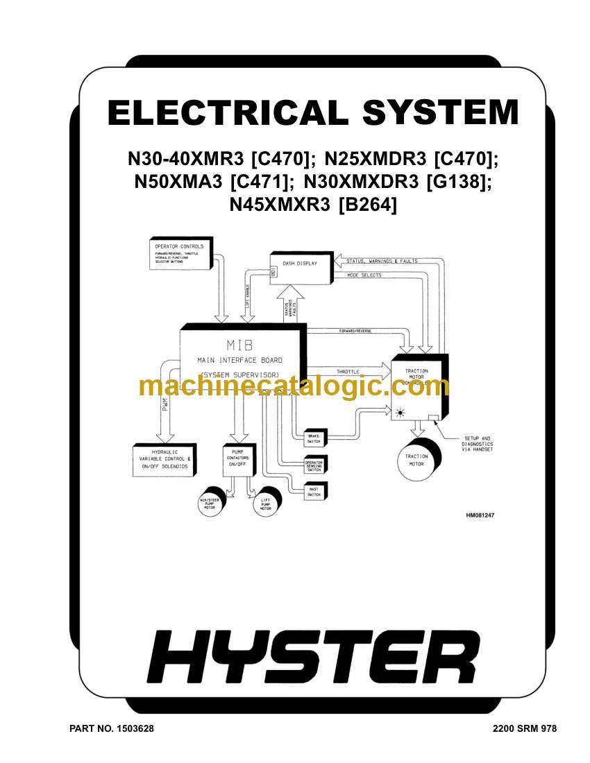
Model: N30XMDR3, N45XMR3 (G138 D829) Forklift

Type of Document: Service Manual

Categories: ,

$ 45

Share:

Hyster N30XMDR3, N45XMR3 (G138 D829) Forklift Service Manual

Hyster N30XMDR3, N45XMR3 (G138 D829) Forklift Service Manual

📘 Show Index

Hyster N30XMDR3, N45XMR3 (G138 D829) Forklift Index:

  • toc
    • Electrical System
    • Safety Precautions Maintenance and Repair
    • General
    • Component Repair and Testing – General
    • Contactor Panel Assembly
      • Description/Features
      • Remove
      • Install
    • Contactors
      • Description/Features
      • Auxiliary Switch
      • Testing
      • Remove
      • Install
      • EE Contactors
    • Fuses
    • Relays
      • Description/Features
      • Enable Relay
      • Hourmeter Relay
      • Lift/Lower Relay (Trucks Built After 1 August 2002)
      • Coil Testing
      • Contact Testing
      • Remove and Install
    • Height Proximity Switch
      • Remove
      • Test
      • Install
      • Adjust
    • Key Switch
      • Description
      • Remove
      • Install
    • Battery Disconnect Switch
      • Description
      • Remove
      • Install
    • Proportional Electro-Hydraulic Control Valves
      • Manual Lowering
      • Operation
      • Repair
    • Carriage Valve Assembly and Selector Valves
      • Test/Remove/Install
    • Multifunction Control Handle
      • Description/Features
      • Remove
      • Disassemble
      • Assemble
      • Install
    • Shelf Height Selector
      • Description/Features
      • Programming
      • System Errors
      • Main Interface Board (MIB) Adjustments
    • Main Interface Board (MIB)
      • Description/Features
      • Operation
      • LED Display
      • MIB, Remove
      • MIB J-Connector, Repair
      • MIB, Install
    • Main Interface Board (MIB) Setup Procedures
      • General
      • Default Values
      • Checking Model Code, Software Version, and Setup Status
      • MIB Generation II Setup Procedure
      • Max Speed and Low End Adjustments
      • Customizing MIB Functions
    • MIB Status, Warning, and Fault Codes
      • General
      • Troubleshooting Charts
    • Blank or Undefined Code Conditions
    • Status Codes
    • Warning Codes
    • Fault Codes
    • SEM Traction Motor Controller
      • Description/Features
      • Remove
      • Test
      • Install
    • 1307 Programmer Handset
      • Description/Features
      • SCROLL DISPLAY Keys
      • CHANGE VALUE Keys
      • MORE INFO Key
      • Operation
      • Operating Modes
    • Programming the Traction Motor Controller – 1307 Handset
    • 1311 Programmer Handset
      • Description/Features
      • Operation
      • Main Menu Selections
    • Programming the Traction Motor Controller – 1311 Handset
    • Troubleshooting
      • Status LED Diagnostics
      • Programmer Diagnostics
      • Diagnostics Menu
      • Test Menu
    • Dash Display Assembly
      • Description and Features
      • Operation
      • Remove
      • Install
      • Voltage Selection
      • Dash Display, Adjust
      • Battery Indicator Profile Settings
      • Troubleshooting
  • tables
    • Table 1. Contactor Coil Voltages
    • Table 2. Fuses
    • Table 3. Hydraulic Control Valve/Relay Coil Resistance Values
    • Table 4. OPTS Bits
    • Table 5. Truck Unit and Model Codes
    • Table 6. MIB Function Code Values for N30XMR3 Software 06/01/01
    • Table 7. MIB Function Code Values for N40XMR3 06/01/01 to 01/14/
    • Table 8. MIB Function Code Values for N25XMDR3
    • Table 9. MIB Function Code Values for N50XMA3
    • Table 10. MIB Function Code Values for N45XMR3
    • Table 11. MIB Function Code Values for N30XMDR3
    • Table 12. MIB Function Code Values for N45XMXR3 Mast Full Height
    • Table 13. MIB Function Code Values for N45XMXR3 Mast Full Height
    • Table 14. MIB Function Code Values for N30XMXDR Mast Full Height
    • Table 15. MIB Function Code Values for N30XMXDR Mast Full Height
    • Table 16. MIB Software 01/14/02 to 03/27/02
    • Table 17. MIB Software 01/14/02 to 03/27/02 NXMR3 and NXMXR3 (G1
    • Table 18. MIB Software Post 03/27/02 NXMR3, NXMDR3 C470
    • Table 19. MIB Software Post 03/27/02 NXMR3, NXMDR3 (G138) and N3
    • Table 20. NXMXDR3, NXMXR3 (B264)
    • Table 21. Program Menu
    • Table 22. Test Menu
    • Table 23. Dash Display Drive Mode Inputs
    • Table 24. Diagnostic and Diagnostic History Display
    • Table 25. Special Program Menu
    • Table 26. Program Menu Range and Default Values
    • Table 27. Status LED Fault Codes
    • Table 28. Dash Display Drive Mode Inputs
    • Table 29. Dash Display Drive Mode Test Voltages
    • Table 30. Dash Display Status/Warning/Fault Test Voltages
  • toc
    • Steering System
    • Safety Precautions Maintenance and Repair
    • General
    • Description
    • Steering Control Unit Assembly
      • Description
      • Remove
    • Steering Control Unit
      • Description
      • Operation
      • Remove
      • Repair
      • Install
    • Steering Pump and Motor Assembly
      • Description
      • Pump and Motor
      • Pump
    • Axle Assembly Repair
      • General
      • Traction Motor
      • Master Drive Unit
      • Hydraulic Steering Motor
      • Caster Wheels
      • Axle Weldment
      • Check and Adjust
    • Troubleshooting
  • tables
    • Table 1. Articulation Adjustment Chart

Hyster

Latest Product

0
    0
    Your Cart
    Your cart is emptyReturn to Shop