John Deere 318E and 320E Skid Steer Loaders Operation and Test Technical Manual (TM13006X19)
You’ve got a 318E throwing a hydraulic warning, boom’s dead in the air, operator staring at you. You can poke around for two hours, or you can open TM13006X19 and go straight to the right test port, the right connector, and the right spec. That’s how this thing prevents downtime: it tells you exactly what “normal” looks like on this machine, so you stop guessing and start proving.
Key Tasks Covered:
- Trace hydraulic warning codes to specific pressure, flow, or temp tests.
- Pin‑out and voltage test every major controller and sensor on 318E/320E.
- Run step‑by‑step HST and drive motor performance checks under load.
- Verify pilot control pressures and boom/bucket circuit relief settings.
- Diagnose CAN bus issues between display, ECU, and hydraulic controller.
Common Questions:
Q: “Pump sounds fine, but I’ve got weak hydraulics and no codes. Now what?”
A: Manual walks you to charge pressure and main pump standby pressure tests; if either’s low, you adjust relief or condemn the pump with numbers, not guesses.
Q: “Machine won’t move, park brake light’s off, what am I missing?”
A: It has you check drive enable circuit voltage, seat switch input, then servo pressure—usually finds a dead interlock or no pilot pressure.
Safety Note
Always mechanically support the boom before cracking any hydraulic line, no exceptions.
John Deere 318E and 320E Skid Steer Loaders Index:
- Contents
- General Information
- Safety
- Recognize Safety Information
- Follow Safety Instructions
- Operate Only If Qualified
- Wear Protective Equipment
- Avoid Unauthorized Machine Modifications
- Inspect Machine
- Stay Clear of Moving Parts
- Avoid High-Pressure Fluids
- Avoid High-Pressure Oils
- Work In Ventilated Area
- Prevent Fires
- Prevent Battery Explosions
- Handle Chemical Products Safely
- Dispose of Waste Properly
- Prepare for Emergencies
- Clean Debris from Machine
- Use Steps and Handholds Correctly
- Start Only From Operator’s Seat
- Use and Maintain Seat Belt
- Prevent Unintended Machine Movement
- Avoid Work Site Hazards
- Keep Riders Off Machine
- Avoid Backover Accidents
- Avoid Machine Tip Over
- Operating On Slopes
- Operating or Traveling On Public Roads
- Inspect and Maintain ROPS
- Add and Operate Attachments Safely
- Park and Prepare for Service Safely
- Service Cooling System Safely
- Remove Paint Before Welding or Heating
- Make Welding Repairs Safely
- Drive Metal Pins Safely
- Handle Cab Door Safely
- Clean Exhaust Filter Safely
- Diagnostics
- Engine Control Unit (ECU) Diagnostic Trouble Codes
- Engine Control Unit (ECU) Diagnostic Trouble Codes
- 000028.00 — Accelerator 3 / Pedal
- 000028.01 — Accelerator 3 / Pedal
- 000028.03 — Accelerator 3 / Pedal
- 000028.04 — Accelerator 3 / Pedal
- 000029.03 — Accelerator 2 / Pedal
- Engine Speed Control Pedal Out of Range High Diagnostic Procedure
- 000029.04 — Accelerator 2 / Pedal
- Engine Speed Control Pedal Out of Range High Diagnostic Procedure
- 000091.03 — Acceleration / Sensor 1
- Engine Speed Control Dial Out of Range High Diagnostic Procedure
- 000091.04 — Acceleration / Sensor 1
- Engine Speed Control Dial Out of Range High Diagnostic Procedure
- 000167.01 — Charge / Alarm
- Alternator Potential Volts Too Low Diagnostic Procedure
- 000167.05 — Charge / Alarm
- Alternator Current Below Normal Diagnostic Procedure
- 000237.13 — Vehicle Identification / Number
- Engine Control Unit (ECU) Configuration Invalid Diagnostic Procedure
- 000237.31 — Vehicle Identification / Number
- Invalid Vehicle Identification Number (VIN) Diagnostic Procedure
- 001485.02 — Main Relay / ECU
- ECU Powers Off Diagnostic Procedure
- 001485.07 — Main Relay / ECU
- Mechanical System Not Responding or Out of Adjustment Diagnostic Procedure
- 522243.05 — Start Assist / Relay
- Glow Plug Relay Out of Range Low Diagnostic Procedure
- 522243.06 — Start Assist / Relay
- Glow Plug Relay Out of Range High Diagnostic Procedure
- 522590.12 — Internal / Supply 1
- Supply Voltage Error Diagnostic Procedure
- 522596.09 — CAN Comm / TSC1
- Engine Control Unit (ECU) CAN Data Abnormal Data Rate Diagnostic Procedure
- 522597.09 — TSC1 CAN / Message
- Engine Control Unit (ECU) CAN Data Abnormal Data Rate Diagnostic Procedure
- 522599.09 — Y_RSS CAN / Message
- Engine Control Unit (ECU) CAN Data Abnormal Data Rate Diagnostic Procedure
- 522600.09 — Y_EC CAN / Message
- Engine Control Unit (ECU) CAN Data Abnormal Data Rate Diagnostic Procedure
- 522601.09 — Y_RSS CAN / Message
- Engine Control Unit (ECU) CAN Data Abnormal Data Rate Diagnostic Procedure
- 522618.09 — EBC1 CAN / Message
- Engine Control Unit (ECU) CAN Data Abnormal Data Rate Diagnostic Procedure
- 522619.09 — Y_DPFIF CAN / Message
- Engine Control Unit (ECU) CAN Data Abnormal Data Rate Diagnostic Procedure
- 522623.07 — Accelerator 1-2 Sensor
- 522624.07 — Accelerator 1-2 Sensor
- 522744.04 — Internal Driver / Circuit
- Internal Driver Short to Ground Diagnostic Procedure
- 522994.04 — Internal Driver / Circuit
- Internal Driver Short to Ground Diagnostic Procedure
- Engagement and Monitor Unit (EMU) Diagnostic Trouble Codes
- Engagement and Monitor Unit (EMU) Diagnostic Trouble Codes
- 000070.02 — Park Brake / Release Input
- Park Brake Release Input Erratic or Bad Data Diagnostic Procedure
- 000070.04 — Park Brake / Release Input
- Park Brake Release Input Out of Range Low Diagnostic Procedure
- 000096.03 — Fuel Level / Sensor
- Fuel Level Sensor Out of Range High Diagnostic Procedure
- 000096.04 — Fuel Level / Sensor
- Fuel Level Sensor Out of Range Low Diagnostic Procedure
- 000158.00 — System Voltage
- System Voltage Data Above Normal Diagnostic Procedure
- 000158.01 — System Voltage
- System Voltage Data Below Normal Diagnostic Procedure
- 000162.04 — 2-Speed / Switch Input
- 2-Speed Switch Input Low Diagnostic Procedure
- 000234.14 — Software Mismatch
- Mismatched Software Versions Diagnostic Procedure
- 000920.05 — Alarm Output
- Alarm Output Out of Range Low Diagnostic Procedure
- 000920.06 — Alarm Output
- Alarm Output Out of Range High Diagnostic Procedure
- 001196.11 — Anti Theft
- Anti Theft Unknown Fault Diagnostic Procedure
- 001504.04 — Seat Switch / Input
- Seat Switch Input Out of Range Low Diagnostic Procedure
- 002000.09 — No ECU Data / On CAN Bus
- No ECU Data on CAN Bus Abnormal Data Range Diagnostic Procedure
- 2142.09 — No SSM Data / On CAN Bus
- No SSM Data on CAN Bus Abnormal Data Range Diagnostic Procedure
- 002228.09 — No HCU Data / On CAN Bus
- No HCU Data on CAN Bus Abnormal Data Range Diagnostic Procedure
- 003413.04 — Door Switch / Input
- Cab Door Switch Input Out of Range Low Diagnostic Procedure
- 003597.03 — 5 Volt Sensor / Supply 1
- Sensor Supply Voltage High Diagnostic Procedure
- 003597.04 — 5 Volt Sensor / Supply 1
- Sensor Supply Voltage Low Diagnostic Procedure
- 521050.04 — Aux Flow On-Off / Switch Input
- Switch Input Low Diagnostic Procedure
- 521197.04 — Courtesy Light / Switch Input
- Switch Input Low Diagnostic Procedure
- 522379.05 — Park Brake / Release Output
- Park Brake Release Output Out of Range Low Diagnostic Procedure
- 522379.06 — Park Brake / Release Output
- Park Brake Release Output Out of Range High Diagnostic Procedure
- 522398.02 — Park Brake Run / Switch Input
- Park Brake Release Input Erratic or Bad Data Diagnostic Procedure
- 522398.04 — Park Brake Run / Switch Input
- Park Brake Release Input Out of Range Low Diagnostic Procedure
- 522826.00 — Fan Purge / Switch Input
- Fan Purge Switch Input Out of Range High Diagnostic Procedure
- 522826.04 — Fan Purge / Switch Input
- VSF Purge Switch Input Out of Range Low Diagnostic Procedure
- 522827.04 — Fan Auto / Switch Input
- VSF Purge Switch Input Out of Range Low Diagnostic Procedure
- 522859.04 — Lap Bar/ Switch Input
- Lap Bar Switch Input Out of Range Low Diagnostic Procedure
- 523217.06 — Hydraulic Valve / Power 3 to HCU
- Hydraulic Valve Power 3 Out of Range High Diagnostic Procedure (EH Control Machines)
- Hydraulic Valve Power 3 Out of Range High Diagnostic Procedure (Manual Control Machines)
- 523218.06 — Propel Valve / Power 2 to HCU
- Propel Valve Power 2 to HCU Out of Range High Diagnostic Procedure (EH Control Only)
- 523219.06 — Hydraulic Valve / Power Output
- Hydraulic Valve Power 1 Out of Range High Diagnostic Procedure (EH Control Machines)
- Hydraulic Valve Power 3 Out of Range High Diagnostic Procedure (Manual Control Machines)
- 523693.03 — Aux Hyd / Channel 1 Input
- Aux Hyd Channel 1 Input High Diagnostic Procedure
- 523693.04 — Aux Hyd / Channel 1 Input
- Aux Hyd Channel 1 Input Low Diagnostic Procedure
- 523694.03 — Aux Hyd / Channel 2 Input
- Aux Hyd Channel 2 Input High Diagnostic Procedure
- 523694.04 — Aux Hyd / Channel 2 Input
- Aux Hyd Channel 2 Input Low Diagnostic Procedure
- 523694.12 — Aux Hyd / Channel 2 Input
- Aux Hyd Channel 2 Input Device Fault Diagnostic Procedure
- 523822.04 — High Flow / Switch Input
- High Flow Switch Input Out of Range Low Diagnostic Procedure
- 523935.05 — Aux Hyd / Extend Output
- Aux Hyd Extend Output Out of Range Low Diagnostic Procedure
- 523935.06 — Aux Hyd / Extend Output
- Hydraulic Valve Power 1 Out of Range High Diagnostic Procedure
- 523941.05 — Aux Hyd / Retract Output
- Hydraulic Valve Power 1 Out of Range High Diagnostic Procedure
- 523941.06 — Aux Hyd / Retract Output
- Hydraulic Valve Power 1 Out of Range High Diagnostic Procedure
- 523948.05 — Ride Control 1 / Solenoid Current
- Ride Control Accumulator Output Out of Range Low Diagnostic Procedure
- 523948.06 — Ride Control 1 / Solenoid Current
- Ride Control Accumulator Solenoid Output Out of Range High Diagnostic Procedure
- 523949.05 — Ride Control 2 / Solenoid Current
- Ride Control Reservoir Solenoid Output Out of Range Low Diagnostic Procedure
- 523949.06 — Ride Control 2 / Solenoid Current
- Ride Control Reservoir Solenoid Out of Range High Diagnostic Procedure
- 524225.04 — Remote Start / Input
- Remote Start Input Out of Range Low Diagnostic Procedure
- 524264.11 — Checksum Error
- Checksum Error Unknown Fault Diagnostic Procedure
- Sealed Switch Module (SSM) Diagnostic Trouble Codes
- Sealed Switch Module (SSM) Diagnostic Trouble Codes
- 0000629.12 — Controller Fault
- Sealed Switch Module (SSM) Watchdog Time Out Diagnostic Procedure
- 002033.09 — VCU CAN Comm
- Sealed Switch Module Lost Communications with VCU Diagnostic Procedure
- 002634.04 — Ignition Relay
- Sealed Switch Module (SSM) Accessory Relay Signal Short to Ground Diagnostic Procedure
- 002634.05 — Ignition Relay
- Sealed Switch Module (SSM) Accessory Relay Signal Open Circuit Diagnostic Procedure
- 523850.04 — SSM Button 15
- Button 15 on Keypad Stuck Diagnostic Procedure
- 523850.09 — SSM Button 15
- No LED Response Diagnostic Procedure
- 523852.04 — SSM Button 14
- Button 14 on Keypad Stuck Diagnostic Procedure
- 523852.09 — SSM Button 14
- No LED Response Diagnostic Procedure
- 523854.04 — SSM Button 13
- Button 13 on Keypad Stuck Diagnostic Procedure
- 523854.09 — SSM Button 13
- No LED Response Diagnostic Procedure
- 523855.04 — SSM Button 12
- Creep Mode Switch on Keypad Stuck Diagnostic Procedure
- 523855.09 — SSM Button 12
- No LED Response Diagnostic Procedure
- 523856.04 — SSM Button 11
- Ride Control Switch on Keypad Stuck Diagnostic Procedure
- 523856.09 — SSM Button 11
- No LED Response Diagnostic Procedure
- 523857.04 — SSM Button 10
- Hydraulic Response Switch on Keypad Stuck Diagnostic Procedure
- 523857.09 — SSM Button 10
- No LED Response Diagnostic Procedure
- 523858.04 — SSM Button 9
- Pattern Select Switch on Keypad Stuck Diagnostic Procedure
- 523858.09 — SSM Button 9
- No LED Response Diagnostic Procedure
- 523860.04 — SSM Button 8
- Button 8 on Keypad Stuck Diagnostic Procedure
- 523860.09 — SSM Button 8
- No LED Response Diagnostic Procedure
- 523861.04 — SSM Button 7
- Transmission Response Switch on Keypad Stuck Diagnostic Procedure
- 523861.09 — SSM Button 7
- No LED Response Diagnostic Procedure
- 523862.04 — SSM Button 6
- Button 6 on Keypad Stuck Diagnostic Procedure
- 523862.09 — SSM Button 6
- No LED Response Diagnostic Procedure
- 523863.04 — SSM Button 5
- Button 5 on Keypad Stuck Diagnostic Procedure
- 523863.09 — SSM Button 5
- No LED Response Diagnostic Procedure
- 523864.04 — SSM Button 4
- Park Brake Switch on Keypad Stuck Diagnostic Procedure
- 523864.09 — SSM Button 4
- No LED Response Diagnostic Procedure
- 523865.04 — SSM Button 3
- Hydraulic Enable Switch on Keypad Stuck Diagnostic Procedure
- 523865.09 — SSM Button 3
- No LED Response Diagnostic Procedure
- 523867.04 — SSM Button 2
- Engine Stop Switch on Keypad Stuck Diagnostic Procedure
- 523867.09 — SSM Button 2
- No LED Response Diagnostic Procedure
- 523868.04 — SSM Button 1
- Engine Start Switch on Keypad Stuck Diagnostic Procedure
- 523868.09 — SSM Button 1
- No LED Response Diagnostic Procedure
- Vehicle Control Unit (VCU) Diagnostic Trouble Codes
- Vehicle Control Unit (VCU) Diagnostic Trouble Codes
- 000158.03 — Battery Voltage Switched Power
- Switched Power Input Out of Range High Diagnostic Procedure
- 000158.04 — Battery Voltage Switched Power
- Switched Power Input Out of Range Low Diagnostic Procedure
- 000168.03 — Unswitched Power / Input
- Unswitched Power Input Out of Range High Diagnostic Procedure
- 000168.04 — Unswitched Power / Input
- Unswitched Power Input Out of Range Low Diagnostic Procedure
- 000977.05 — Fan Direction / Mode
- Hydraulic Reversing Fan Solenoid B Current Out of Range Low Diagnostic Procedure
- 000977.06 — Fan Direction / Mode
- Reversing Hydraulic Fan Speed Solenoid Current Out of Range High Diagnostic Procedure
- 001071.05 — Fan Speed / Solenoid
- Fan Solenoid Current Out of Range High Diagnostic Procedure
- 001071.06 — Fan Speed / Solenoid
- Fan Solenoid Current Out of Range Low Diagnostic Procedure
- 001508.00 — Hydraulic Oil / Temperature
- Hydraulic Oil High Temperature Diagnostic Procedure
- 001508.03 — Hydraulic Oil / Temperature
- Hydraulic Oil Temperature Sensor Short to Power Diagnostic Procedure
- 001508.04 — Hydraulic Oil / Temperature
- Hydraulic Oil Temperature Sensor Out of Range Low Diagnostic Procedure
- 001713.00 — Hydraulic Filter / Restr Switch
- Hydraulic Oil Filter Restricted Diagnostic Procedure
- 001713.03 — Hydraulic Filter / Restr Switch
- Hydraulic Filter Restriction Switch Short to Power Diagnostic Procedure
- 003599.03 — 5 Volt Sensor – Supply 3
- 003599.04 — 5 Volt Sensor – Supply 3
- 004056.05 — 2-Speed Output
- Two Speed Solenoid Current Out of Range Low Diagnostic Procedure
- 004056.06 — 2-Speed Output
- Two Speed Solenoid Current Out of Range High Diagnostic Procedure
- 516249.04 — Controller Power Supply
- Controller Power Supply Low Diagnostic Procedure
- 520194.13 — Machine Model ID / Wrong or Missing
- Hydraulic Control Unit (HCU) Configuration Invalid Diagnostic Procedure
- 520194.14 — Machine Model ID / Wrong or Missing
- Hydraulic Control Unit (HCU) Configuration Invalid Diagnostic Procedure
- 521466.05 — Fan Direction / Relief
- Hydraulic Reversing Fan Solenoid A Current Out of Range Low Diagnostic Procedure
- 521466.06 — Fan Direction / Relief
- Hydraulic Reversing Fan Solenoid A Current Out of Range High Diagnostic Procedure
- 521806.05 — HST Bypass Solenoid
- Hydrostatic Bypass Solenoid Out of Range Low Diagnostic Procedure
- 521806.06 — HST Bypass Solenoid
- Hydrostatic Bypass Solenoid Out of Range High Diagnostic Procedure
- 522820.05 — High Flow / Driver
- High Flow Solenoid Current Out of Range Low Diagnostic Procedure
- 522820.06 — High Flow / Driver
- High Flow Solenoid Current Out of Range High Diagnostic Procedure
- 524084.00 — Hydrostat Oil / Temperature
- Hydrostatic Oil High Temperature Diagnostic Procedure
- 524084.03 — Hydrostat Oil / Temperature
- Hydrostatic Oil Temperature Sensor Short to Power Diagnostic Procedure
- 524084.04 — Hydrostat Oil / Temperature
- Hydrostatic Oil Temperature Sensor Out of Range Low Diagnostic Procedure
- 524264.11 — Checksum Error
- Checksum Error Diagnostic Procedure
- Operational Checkout Procedure
- Operational Checkout Procedure
- Operational Checkout
- Diagnostic Trouble Code Check
- Operational Checks—Switched Power OFF, Engine OFF Checks
- Operational Checks—Switched Power ON, Engine OFF Checks
- Operational Checks—Switched Power ON, Engine ON Checks
- Engine
- Theory of Operation
- John Deere Engine
- Engine Identification
- Cold Start Operation
- Diagnostic Information
- John Deere Engine
- Engine Cooling System Component Location
- Engine Fuel System Component Location
- Engine Intake and Exhaust Component Location
- Engine Hard to Start or Does Not Start When Cold
- Engine Hard to Start or Does Not Start When Cold Diagnostic Procedure
- Electrical System
- System Information
- Electrical Diagram Information
- Electrical Schematic Symbols
- System Diagrams
- Fuse and Relay Specifications
- System Functional Schematic, Wiring Diagram and Component Location Master Legend
- System Functional Schematic
- Rear Engine Harness (W1) Component Location
- Rear Engine Harness (W1) Wiring Diagram
- Cab Harness (W2) Component Location
- Cab Harness (W2) Wiring Diagram
- Main Harness (W3) Component Location
- Main Harness (W3) Wiring Diagram
- Reverse Switch Harness (W4) Component Location
- Reverse Switch Harness (W4) Wiring Diagram
- Dual Flasher Harness (W5) Component Location
- Dual Flasher Harness (W5) Wiring Diagram
- Control Lever Harness (W6) Component Location
- Control Lever Harness (W6) Wiring Diagram
- Radio Harness (W8) Component Location
- Radio Harness (W8) Wiring Diagram
- Hydraulic Valve Harness (W10) Component Location
- Hydraulic Valve Harness (W10) Wiring Diagram
- Attachment Control Frame Harness (W11) Component Location
- Attachment Control Frame Harness (W11) Wiring Diagram
- Attachment Control Boom Harness (W12) Component Location
- Attachment Control Boom Harness (W12) Wiring Diagram
- Quik-Tatch™ Frame Harness (W13) Component Location
- Quik-Tatch™ Frame Harness (W13) Wiring Diagram
- Quik-Tatch™ Boom Harness (W14) Component Location
- Quik-Tatch™ Boom Harness (W14) Wiring Diagram
- Quik-Tatch™ Actuator Harness (W15) Component Location
- Quik-Tatch™ Actuator Harness (W15) Wiring Diagram
- Heater and Air Conditioner Harness (W16) Component Location
- Heater and Air Conditioner Harness (W16) Wiring Diagram
- Hydrostatic Control Valve Harness (W17) Component Location
- Hydrostatic Control Valve Harness (W17) Wiring Diagram
- High/Low Pressure Switch and Heater Valve Motor Harness (W18) Component Location
- High/Low Pressure Switch and Heater Valve Motor Harness (W18) Wiring Diagram
- Engine Harness (W21) Component Location
- Engine Harness (W21) Wiring Diagram
- Engine Fuel System Harness (W22) Component Location
- Engine Fuel System Harness (W22) Wiring Diagram
- Sub-System Diagnostics
- Starting Circuit Theory of Operation
- Controller Area Network (CAN) Theory of Operation
- Engine Control Unit (ECU) Circuit Theory of Operation
- Engagement and Monitor Unit (EMU) Circuit Theory of Operation
- Lighting Circuit Theory of Operation
- Hydraulic System Control Circuit Theory of Operation
- Hydrostatic System Control Circuit Theory of Operation
- Hydraulic Fan Control Circuit Theory of Operation
- Backup Alarm Circuit Theory of Operation
- Quik-Tatch Circuit Theory of Operation—If Equipped
- Monitor Operation
- Engagement and Monitor Unit Operation
- Engagement and Monitor Unit Data Items
- Engagement and Monitor Unit Display Messages
- Engagement and Monitor Unit Service Menu Operation
- Engagement and Monitor Unit Initial Configuration
- Anti-Theft Security System Operation—If Equipped
- Anti-Theft Security System Configuration—If Equipped
- Anti-Theft Security System Enable—If Equipped
- References
- Service ADVISOR™ Connection Procedure
- Reading Diagnostic Trouble Codes (DTCs)
- Intermittent Diagnostic Trouble Code (DTC) Diagnostics
- Electrical Component Checks
- Electrical Component Specifications
- Solenoid Test
- Solenoid Observable Symptom Check
- Alternator Test
- Controller Area Network (CAN) Circuit Test
- Controller Area Network (CAN) Diagnostics
- Auxiliary Hydraulics Calibration
- Engine Control Unit (ECU) Remove and Install
- Vehicle Control Unit (VCU) Remove and Install
- Engagement and Monitor Unit (EMU) Remove and Install
- Control Panel Remove and Install
- Backup Alarm Remove and Install
- Battery Remove and Install
- Replace (Pull Type) Metri-Pack™ Connectors
- Replace (Push Type) Metri-Pack™ Connectors
- Replace Metri-Pack™ Connectors
- Replace WEATHER PACKWEATHER PACK is a trademark of Packard Electric.™ Connector
- Install WEATHER PACKWEATHER PACK is a trademark of Packard Electric.™ Contact
- Replace DEUTSCHDEUTSCH is a trademark of Deutsch Co.™ Rectangular or Triangular Connectors
- Replace DEUTSCHDEUTSCH is a trademark of the Deutsch Co.™ Circular Connectors
- Replace DEUTSCHDEUTSCH is a trademark of the Deutsch Co.™ Connectors
- Install DEUTSCHDEUTSCH is a trademark of the Deutsch Co.™ Contact
- Replace CINCH™ Connectors
- Install CINCH™ Contact
- Repair 32 and 48 Way CINCH™ Connectors
- Remove Connector Body from Blade Terminals
- Power Train
- Theory of Operation
- Power Train System Operation
- Chain Case Operation
- Drive Chain Operation
- Drive Axle Operation
- Diagnostic Information
- Power Train Component Location
- Oil Leak From Power Train
- Oil Leak From Power Train Diagnostic Procedure
- Excessive Axle Play
- Excessive Axle Play Diagnostic Procedure
- Drive Chain Noise
- Drive Chain Noise Diagnostic Procedure
- Grinding Noise
- Grinding Noise Diagnostic Procedure
- One Drive Wheel Not Powered
- One Drive Wheel Not Powered Diagnostic Procedure
- Both Wheels On One Side Not Powered
- Tests
- Drive Chain Tension Check and Adjustment
- Hydraulic System
- Theory of Operation
- Hydraulic System Operation
- Hydraulic Oil Filter Manifold Operation
- High Flow Pump Operation—If Equipped
- Self Leveling Valve Operation—If Equipped
- Ride Control Operation—If Equipped
- Hydraulic Pump Operation
- Hydraulic Fan Operation
- Hydraulic Control Valve Operation
- Diagnostic Information
- Hydraulic System Schematic
- Hydraulic System Component Location
- Diagnose Hydraulic System Malfunctions
- No Hydraulic Functions
- No Hydraulic Functions Diagnostic Procedure
- Boom Will Not Raise
- Boom Will Not Raise Diagnostic Procedure
- Boom Will Not Lower
- Boom Will Not Lower Diagnostic Procedure
- Bucket Will Not Dump
- Bucket Will Not Dump Diagnostic Procedure
- Bucket Will Not Curl
- Bucket Will Not Curl Diagnostic Procedure
- Bucket Will Not Self Level When Boom is Raised
- Bucket Will Not Self Level When Boom is Raised Diagnostic Procedure
- Bucket Dumps During Self Leveling Cycle
- Bucket Dumps During Self Leveling Cycle Diagnostic Procedure
- Boom Drifts Down
- Boom Drifts Down Diagnostic Procedure
- Boom Drifts Up
- Boom Drifts Up Diagnostic Procedure
- Bucket Drifts Down
- Bucket Drifts Down Diagnostic Procedure
- Bucket Drifts Up
- Bucket Drifts Up Diagnostic Procedure
- Hydraulic Functions Slow or No Power
- Hydraulic Functions Slow or No Power Diagnostic Procedure
- Hydraulic Functions “Jerky” or “Spongy”
- Hydraulic Functions “Jerky” or “Spongy” Diagnostic Procedure
- Hydraulic System Noise
- Hydraulic System Noise Diagnostic Procedure
- Pedals Will Not Move
- Pedals Will Not Move Diagnostic Procedure
- Hydraulic Oil Overheats
- Hydraulic Oil Overheats Diagnostic Procedure
- Hydraulic Fan System Malfunctions
- Hydraulic Fan System Malfunctions Diagnostic Procedure
- Hydraulic Fan Will Not Reverse Direction
- Hydraulic Fan Will Not Reverse Direction Diagnostic Procedure
- Adjustments
- Ride Control Accumulator Gas Charge Procedure—If Equipped
- Tests
- JT05800 Digital Thermometer Installation
- JT02156A Digital Pressure and Temperature Analyzer Kit Installation
- Remote Start Box Installation
- Hydraulic System Pressure Release
- Boom Release Cable Adjustment
- Pilot Control Accumulator Precharge Test
- Port Lock Solenoid Valve and Port Lock Spool Test
- Boom and Bucket Spool Lock Solenoid Test
- Hydraulic System Relief Valve Test
- Charge Pressure Relief Valve Test
- Circuit Relief Valve Test
- Function Drift Test
- Hydraulic Cylinder Leakage Test
- Hydraulic Pump Flow Test
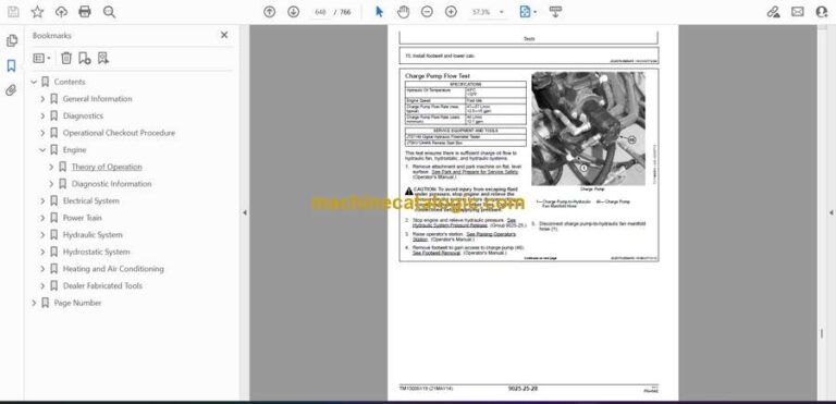
- Charge Pump Flow Test
- Hydraulic Fan Motor Speed Test
- Hydraulic Fan Motor Case Drain Test
- Hydraulic Oil Cooler Bypass Valve Test
- Hydrostatic System
- Theory of Operation
- Hydrostatic System Operation
- Hydrostatic Pump Operation
- Charge Pump Operation
- Hydrostatic Motor Operation—Single Speed
- Hydrostatic Motor Operation—Two Speed
- Hydrostatic Control Valve Operation
- Park Brake System Operation
- Steering Control Operation
- Diagnostic Information
- Hydrostatic System Schematic
- Hydrostatic System Component Location
- Machine Does Not Move In Either Direction
- Machine Does Not Move In Either Direction Diagnostic Procedure
- Hydrostatic Pump Or Hydrostatic Motor Noise
- Hydrostatic Pump Or Hydrostatic Motor Noise Diagnostic Procedure
- Slow Response To Changes In Speed
- Slow Response To Changes In Speed Diagnostic Procedure
- Low Power
- Low Power Diagnostic Procedure
- Wheels Powered On One Side, Not The Other
- Wheels Powered On One Side, Not The Other Diagnostic Procedure
- Machine Will Not Shift Into Or Out Of High Speed
- Machine Will Not Shift Into Or Out Of High Speed Diagnostic Procedure
- Machine Creeps With Steering Levers In Neutral
- Machine Creeps With Steering Levers In Neutral Diagnostic Procedure
- Hydrostatic System Noise While In Neutral
- Hydrostatic System Noise While In Neutral Diagnostic Procedure
- Steering Levers Hard To Move
- Steering Levers Hard To Move Diagnostic Procedure
- Steering Levers Feel Loose Or “Sloppy”
- Steering Levers Feel Loose Or “Sloppy” Diagnostic Procedure
- Machine Tracks To One Side With Steering Levers In Full Forward Or Reverse Position
- Machine Tracks To One Side With Steering Levers In Full Forward Or Reverse Position Diagnostic Procedure
- Steering Levers Pulse Or Vibrate Excessively
- Steering Levers Pulse Or Vibrate Excessively Diagnostic Procedure
- Park Brakes Do Not Hold
- Park Brakes Do Not Hold Diagnostic Procedure
- Park Brakes Do Not Release
- Park Brakes Do Not Release Diagnostic Procedure
- Grinding Noise While Operating Machine
- Grinding Noise While Operating Machine Diagnostic Procedure
- Tests
- Engine Speed Control for Testing
- Multi-Function Valve Pressure Relief Test
- Hydrostatic Pump Flow Test
- Centering Plate Adjustment
- Steering Lever Adjustment—Centering
- Tracking Adjustment
- Hydraulic Control Handle Adjustment—Hands Only Machine
- Wheel Speed Test
- Park Brake Release Pressure Test
- Hydrostatic Motor Case Drain Test—Single Speed
- Heating and Air Conditioning
- Theory of Operation
- Air Conditioning System Cycle of Operation
- Diagnostic Information
- Air Conditioning and Heater System Component Location
- Air Conditioning System Does Not Operate
- Air Conditioning System Does Not Operate Diagnostic Procedure
- Air Conditioning Does Not Cool Interior of Cab
- Air Conditioning Does Not Cool Interior of Cab Diagnostic Procedure
- Air Conditioner Runs Constantly, Too Cool
- Air Conditioner Runs Constantly, Too Cool Diagnostic Procedure
- Heater System Does Not Operate
- Heater System Does Not Operate Diagnostic Procedure
- Heater Does Not Warm Interior of Cab
- Heater Does Not Warm Interior of Cab Diagnostic Procedure
- Interior Windows Continue to Fog
- Interior Windows Continue to Fog Diagnostic Procedure
- Tests
- Refrigerant Cautions and Proper Handling
- Air Conditioner and Heater Operational Checks
- Visual Inspection Of Components
- Refrigerant Leak Testing
- Air Conditioner Compressor Clutch Test
- Air Conditioning High/Low Pressure Switch Test
- Air Conditioner Freeze Control Switch Test
- R134a Refrigerant Cautions
- R134a Oil Charge Capacity
- R134a Refrigerant Charge Capacity
- Operating Pressure Diagnostic Chart
- Dealer Fabricated Tools
- Dealer Fabricated Tools
- DFT1325 Solenoid Power Harness
- Page Number
- Section 9000
- Section 9001
- Group 10
- Group 20
- Group 60
- Group 70
- Section 9005
- Section 9010
- Section 9015
- Group 05
- Group 10
- Group 15
- Group 16
- Group 20
- Section 9020
- Group 05
- Group 15
- Group 25
- Section 9025
- Group 05
- Group 15
- Group 20
- Group 25
- Section 9026
- Group 05
- Group 15
- Group 25
- Section 9031
- Group 05
- Group 15
- Group 25
- Section 9900
John Deere
