10% OFF on all manuals and programs. Use code: MCAT10
$ 0
0
$ 0
0

John Deere 770G, 770GP, 772G, and 772GP Motor Grader Operation and Test Technical Manual

Format: PDF (Printable Document)

File Language: English

File Pages: 1642

File Size: 61.56 MB (Speed Download Link)

Brand: John Deere

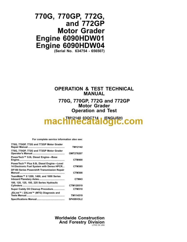
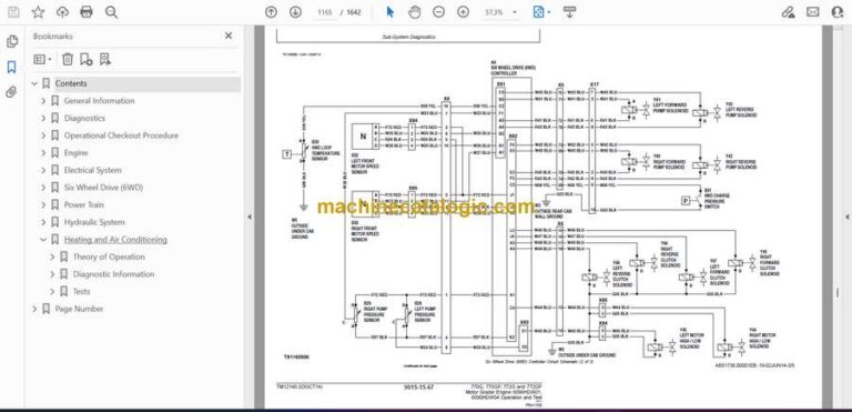
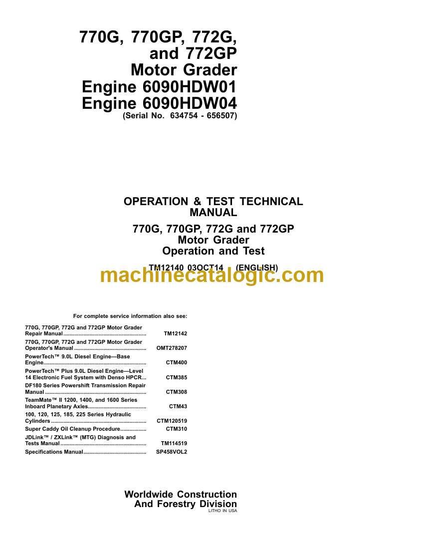
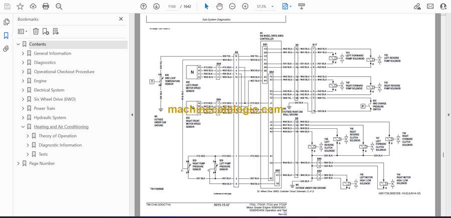
Model: 770G, 770GP, 772G, and 772GP Motor Grader

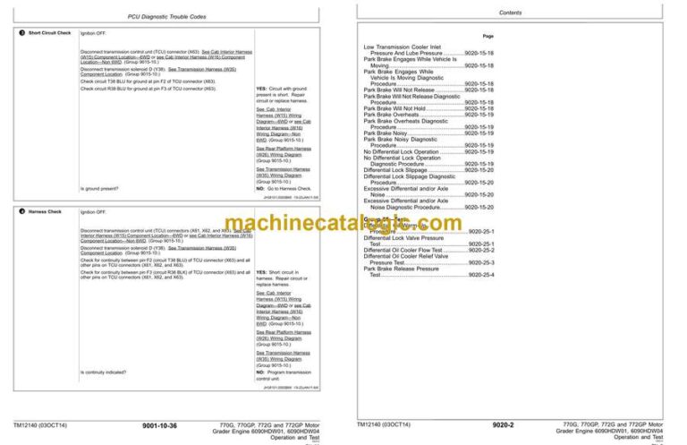
Type of Document: Operation and Test Technical Manual

Excellent Rating (4.8) on Trustpilot · Trusted Worldwide
Categories: ,

$ 45

Share:

John Deere 770G, 770GP, 772G, and 772GP Motor Grader Operation and Test Technical Manual

John Deere 770G, 770GP, 772G, and 772GP Motor Grader Operation and Test Technical Manual

John Deere 770G, 770GP, 772G, and 772GP Motor Grader Index:

  • Contents
    • General Information
      • Safety
        • Recognize Safety Information
        • Follow Safety Instructions
        • Operate Only If Qualified
        • Wear Protective Equipment
        • Avoid Unauthorized Machine Modifications
        • Inspect Machine
        • Stay Clear of Moving Parts
        • Avoid High-Pressure Fluids
        • Avoid High-Pressure Oils
        • Work In Ventilated Area
        • Prevent Fires
        • Prevent Battery Explosions
        • Handle Chemical Products Safely
        • Dispose of Waste Properly
        • Exhaust Filter Ash Handling and Disposal
        • Prepare for Emergencies
        • Clean Debris from Machine
        • Use Steps and Handholds Correctly
        • Start Only From Operator’s Seat
        • Use and Maintain Seat Belt
        • Prevent Unintended Machine Movement
        • Avoid Work Site Hazards
        • Keep Riders Off Machine
        • Avoid Backover Accidents
        • Avoid Machine Tip-Over
        • Operating Or Traveling On Public Roads
        • Inspect and Maintain ROPS
        • Add and Operate Attachments Safely
        • Park and Prepare for Service Safely
        • Clean Exhaust Filter Safely
        • Service Cooling System Safely
        • Remove Paint Before Welding or Heating
        • Make Welding Repairs Safely
        • Drive Metal Pins Safely
        • Service Tires Safely
    • Diagnostics
      • PCU Diagnostic Trouble Codes
        • 000177.00 — Transmission Oil Temperature High
          • Transmission Oil Temperature High Diagnostic Procedure
        • 000177.04 — Transmission Oil Temperature Short To Ground
          • Transmission Oil Temperature Short To Ground Diagnostic Procedure
        • 000525.02 — Program Variable REQ_GEAR Has Taken On An Invalid Value
          • Program Variable REQ_GEAR Has Taken On An Invalid Value Diagnostic Procedure
        • 000525.12 — Request For An Undefined Shift Being Made
          • Request For An Undefined Shift Being Made Diagnostic Procedure
        • 000723.02 — Transmission Input Speed Sensor Bad Data
          • Transmission Input Speed Sensor Bad Data Diagnostic Procedure
        • 002000.02 — ECU CAN Data Invalid
          • ECU CAN Data Invalid Diagnostic Procedure
        • 002000.09 — Can Communication Lost For ECU
          • CAN Communication Lost For ECU Diagnostic Procedure
        • 002033.02 — FLC CAN Data Invalid
          • FLC CAN Data Invalid Diagnostic Procedure
        • 002033.09 — CAN Communication Lost For FLC
          • CAN Communication Lost For FLC Diagnostic Procedure
        • 002225.09 — CAN Communication Lost For Six Wheel Drive
          • CAN Communication Lost For Six Wheel Drive Diagnostic Procedure
        • 522252.00 — Clutch 1 Hold Pressure Too High
          • Clutch 1 Hold Pressure Too High Diagnostic Procedure
        • 522252.01 — Clutch 1 Hold Pressure Too Low
          • Clutch 1 Hold Pressure Too Low Diagnostic Procedure
        • 522253.00 — Clutch 2 Hold Pressure Too High
          • Clutch 2 Hold Pressure Too High Diagnostic Procedure
        • 522253.01 — Clutch 2 Hold Pressure Too Low
          • Clutch 2 Hold Pressure Too Low Diagnostic Procedure
        • 522254.00 — Clutch 3 Hold Pressure Too High
          • Clutch 3 Hold Pressure Too High Diagnostic Procedure
        • 522254.01 — Clutch 3 Hold Pressure Too Low
          • Clutch 3 Hold Pressure Too Low Diagnostic Procedure
        • 522255.00 — Clutch 4 Hold Pressure Too High
          • Clutch 4 Hold Pressure Too High Diagnostic Procedure
        • 522255.01 — Clutch 4 Hold Pressure Too Low
          • Clutch 4 Hold Pressure Too Low Diagnostic Procedure
        • 522256.00 — Clutch A Hold Pressure Too High
          • Clutch A Hold Pressure Too High Diagnostic Procedure
        • 522256.01 — Clutch A Hold Pressure Too Low
          • Clutch A Hold Pressure Too Low Diagnostic Procedure
        • 522257.00 — Clutch B Hold Pressure Too High
          • Clutch B Hold Pressure Too High Diagnostic Procedure
        • 522257.01 — Clutch B Hold Pressure Too Low
          • Clutch B Hold Pressure Too Low Diagnostic Procedure
        • 522258.00 — Clutch C Hold Pressure Too High
          • Clutch C Hold Pressure Too High Diagnostic Procedure
        • 522258.01 — Clutch C Hold Pressure Too Low
          • Clutch C Hold Pressure Too Low Diagnostic Procedure
        • 522259.00 — Clutch D Hold Pressure Too High
          • Clutch D Hold Pressure Too High Diagnostic Procedure
        • 522259.01 — Clutch D Hold Pressure Too Low
          • Clutch D Hold Pressure Too High Diagnostic Procedure
        • 522397.04 — Not In Forward Or Reverse While In Gear
          • Not In Forward Or Reverse While In Gear Diagnostic Procedure
        • 522398.12 — Park And Not Park Both Active
          • Park And Not Park Both Active Diagnostic Procedure
        • 522405.05 — Park Brake Pressure Low At Power-up
          • Park Brake Pressure Low At Power-up Diagnostic Procedure
        • 522413.12 — Gear Bits Active In Park
          • Gear Bits Active In Park Diagnostic Procedure
        • 522414.03 — Transmission Clutch D Short To Power
          • Transmission Clutch D Short To Power Diagnostic Procedure
        • 522414.05 — Transmission Clutch D Open/Short To Ground
          • Transmission Clutch D Open/Short To Ground Diagnostic Procedure
        • 522507.14 — Inching Pedal During Trans Calibration
          • Inching Pedal During Trans Calibration Diagnostic Procedure
        • 522517.31 — Engine Stall Prevention Active
          • Engine Stall Prevention Active Diagnostic Procedure
        • 523655.03 — Forward And Reverse Both Active
          • Forward and Reverse Both Active Diagnostic Procedure
        • 523699.31 — Transmission Speed Clutch Slipping
          • Transmission Speed Clutch Slipping Diagnostic Procedure
        • 523700.00 — Clutch Protection Excessive Inching
          • Clutch Protection Excessive Inching Diagnostic Procedure
        • 523700.16 — Clutch Protection Excessive Inching
          • Clutch Protection Excessive Inching Diagnostic Procedure
        • 523700.31 — Transmission Direction Clutch Slipping
          • Transmission Direction Clutch Slipping Diagnostic Procedure
        • 523708.02 — Inching Switch Signal Bad
          • Inching Switch Signal Bad Diagnostic Procedure
        • 523712.31 — Transmission CAL Without Park Brake Set
          • Transmission CAL Without Park Brake Set Diagnostic Procedure
        • 523717.31 — Helper Clutch Pressure High
          • Helper Clutch Pressure High Diagnostic Procedure
        • 523718.31 — Clutch Drum Speed Decel Excessive
          • Clutch Drum Speed Decel Excessive Diagnostic Procedure
        • 523720.00 — Clutch D Fill Time Too Long
          • Clutch D Fill Time Too Long Diagnostic Procedure
        • 523720.01 — Clutch D Fill Time Too Short
          • Clutch D Fill Time Too Long Diagnostic Procedure
        • 523721.00 — Clutch C Fill Time Too Long
          • Clutch C Fill Time Too Long Diagnostic Procedure
        • 523721.01 — Clutch C Fill Time Too Short
          • Clutch C Fill Time Too Long Diagnostic Procedure
        • 523722.00 — Clutch B Fill Time Too Long
          • Clutch B Fill Time Too Long Diagnostic Procedure
        • 523722.01 — Clutch B Fill Time Too Short
          • Clutch B Fill Time Too Long Diagnostic Procedure
        • 523723.00 — Clutch A Fill Time Too Long
          • Clutch A Fill Time Too Long Diagnostic Procedure
        • 523723.01 — Clutch A Fill Time Too Short
          • Clutch A Fill Time Too Long Diagnostic Procedure
        • 523724.00 — Clutch 4 Fill Time Too Long
          • Clutch 4 Fill Time Too Long Diagnostic Procedure
        • 523724.01 — Clutch 4 Fill Time Too Short
          • Clutch 4 Fill Time Too Long Diagnostic Procedure
        • 523725.00 — Clutch 3 Fill Time Too Long
          • Clutch 3 Fill Time Too Long Diagnostic Procedure
        • 523725.01 — Clutch 3 Fill Time Too Short
          • Clutch 3 Fill Time Too Long Diagnostic Procedure
        • 523726.00 — Clutch 2 Fill Time Too Long
          • Clutch 2 Fill Time Too Long Diagnostic Procedure
        • 523726.01 — Clutch 2 Fill Time Too Short
          • Clutch 2 Fill Time Too Long Diagnostic Procedure
        • 523727.00 — Clutch 1 Fill Time Too Long
          • Clutch 1 Fill Time Too Long Diagnostic Procedure
        • 523727.01 — Clutch 1 Fill Time Too Short
          • Clutch 1 Fill Time Too Long Diagnostic Procedure
        • 523728.31 — Transmission Reverse Cylinder Speed Incorrect At Calibration
          • Transmission Reverse Cylinder Speed Incorrect At Calibration Diagnostic Procedure
        • 523729.31 — Transmission Forward Cylinder Speed Incorrect At Calibration
          • Transmission Reverse Cylinder Speed Incorrect At Calibration Diagnostic Procedure
        • 523730.31 — No Transmission Cylinder Speed During Calibration
          • No Transmission Cylinder Speed During Calibration Diagnostic Procedure
        • 523731.31 — Transmission Output Speed Detected At Calibration
          • Transmission Output Speed Detected At Calibration Diagnostic Procedure
        • 523732.31 — Engine Speed Too Low To Calibrate The Transmission
          • Engine Speed Too Low To Calibrate The Transmission Diagnostic Procedure
        • 523733.31 — Engine Speed Too High To Calibrate The Transmission
          • Engine Speed Too Low To Calibrate The Transmission Diagnostic Procedure
        • 523734.31 — Transmission Too Cold To Calibrate
          • Transmission Too Cold To Calibrate Diagnostic Procedure
        • 523735.04 — Valve Driver Supply Voltage Low
          • Valve Driver Supply Voltage Low Diagnostic Procedure
        • 523736.14 — Bad Gear Position Switch State
          • Bad Gear Position Switch State Diagnostic Procedure
        • 523738.02 — Shifter Handle Problem
          • Shifter Handle Problem Diagnostic Procedure
        • 523738.31 — Shifter Handle Problem
          • Shifter Handle Problem Diagnostic Procedure
        • 523739.31 — Not Park And Forward/Reverse Mismatch
          • Not Park And Forward/Reverse Mismatch Diagnostic Procedure
        • 523740.31 — Forward/Reverse Switch And Gear Mismatch
          • Forward/Reverse Switch And Gear Mismatch Diagnostic Procedure
        • 523741.31 — Started In Gear
          • Started In Gear Diagnostic Procedure
        • 523742.31 — Shifter Vsense Low
          • Shifter Vsense Low Diagnostic Procedure
        • 523747.14 — Park and Not Park Both Passive
          • Park and Not Park Both Passive Diagnostic Procedure
        • 523750.04 — Not Park Passive In Gear Or Neutral
          • Not Park Passive In Gear Or Neutral Diagnostic Procedure
        • 523754.03 — Not Park Active At Startup
          • Not Park Active At Startup Diagnostic Procedure
        • 523755.05 — Park Start Input Passive At Power Up
          • Park Start Input Passive At Power Up Diagnostic Procedure
        • 523761.03 — Transmission Clutch 4 Short To Power
          • Transmission Clutch 4 Short To Power Diagnostic Procedure
        • 523761.05 — Transmission Clutch 4 Open/Short To Ground
          • Transmission Clutch 4 Open/Short To Ground Diagnostic Procedure
        • 523762.03 — Transmission Clutch 3 Short To Power
          • Transmission Clutch 3 Short To Power Diagnostic Procedure
        • 523762.05 — Transmission Clutch 3 Open/Short To Ground
          • Transmission Clutch 3 Open/Short To Ground Diagnostic Procedure
        • 523763.03 — Transmission Clutch 2 Short To Power
          • Transmission Clutch 2 Short To Power Diagnostic Procedure
        • 523763.05 — Transmission Clutch 2 Open/Short To Ground
          • Transmission Clutch 2 Open/Short To Ground Diagnostic Procedure
        • 523764.03 — Transmission Clutch 1 Short To Power
          • Transmission Clutch 1 Short To Power Diagnostic Procedure
        • 523764.05 — Transmission Clutch 1 Open/Short To Ground
          • Transmission Clutch 1 Open/Short To Ground Diagnostic Procedure
        • 524029.00 — Inching Pedal Out Of Range High
          • Inching Pedal Out Of Range High Diagnostic Procedure
        • 524029.01 — Inching Pedal Out Of Range Low
          • Inching Pedal Out Of Range Low Diagnostic Procedure
        • 524029.12 — Inching Pedal Minimum Voltage Exceeds Maximum Voltage
          • Inching Pedal Minimum Voltage Exceeds Maximum Voltage Diagnostic Procedure
        • 524194.07 — Direction Sensor Mismatch
          • Direction Sensor Mismatch Diagnostic Procedure
        • 524271.03 — Transmission Clutch C Short To Power
          • Transmission Clutch C Short To Power Diagnostic Procedure
        • 524271.05 — Transmission Clutch C Open/Short To Ground
          • Transmission Clutch C Open/Short To Ground Diagnostic Procedure
        • 524272.03 — Transmission Clutch B Short To Power
          • Transmission Clutch B Short To Power Diagnostic Procedure
        • 524272.05 — Transmission Clutch B Open/Short To Ground
          • Transmission Clutch B Open/Short To Ground Diagnostic Procedure
        • 524273.03 — Transmission Clutch A Short To Power
          • Transmission Clutch A Short To Power Diagnostic Procedure
        • 524273.05 — Transmission Clutch A Open/Short To Ground
          • Transmission Clutch A Open/Short To Ground Diagnostic Procedure
        • 524275.31 — Forward/Reverse Without Valid Gear
          • Forward/Reverse Without Valid Gear Diagnostic Procedure
      • ECU Diagnostic Trouble Codes
        • 000029.03 — Decel Pedal Short to Power
          • Decel Pedal Short to Power Diagnostic Procedure
        • 000091.03 — Accel Pedal Short to Power
          • Accel Pedal Short to Power Diagnostic Procedure
        • 000091.04 — Accel Pedal Open or Short
          • Accel Pedal Open or Short Diagnostic Procedure
        • 000107.00 — Engine Air Filter Restricted
          • Engine Air Filter Restricted Diagnostic Procedure
        • 000596.31 — Engine Speed Control Enable Switch Fault
          • Engine Speed Control Enable Switch Fault Diagnostic Procedure
        • 000600.31 — Engine Speed Accel/ Decel Switch Fault
          • Engine Speed Accel/ Decel Switch Fault Diagnostic Procedure
        • 001196.31 — ECU Anti Theft Locked
          • ECU Anti Theft Locked Diagnostic Procedure
        • 001321.05 — Starter Relay Open Circuit
          • Starter Relay Open Circuit Diagnostic Procedure
        • 001321.06 — Starter Relay High Current
          • Starter Relay High Current Diagnostic Procedure
        • 001321.30 — Starter Engaged for 30 Seconds
          • Starter Engaged for 30 Seconds Diagnostic Procedure
        • 001321.31 — Starter Solenoid Open Circuit
          • Starter Solenoid Open Circuit Diagnostic Procedure
        • 002003.09 — CAN Communication Lost For TCU
          • CAN Communication Lost For TCU Diagnostic Procedure
        • 002033.09 — CAN Communication Lost For FLC
          • CAN Communication Lost For FLC Diagnostic Procedure
        • 003353.31 — Alternator Output Fault
      • ADU Diagnostic Trouble Codes
        • 000158.03 — Switched Power Voltage High
          • Switched Power Voltage High Diagnostic Procedure
        • 000158.04 — Switched Power Voltage Low
          • Switched Power Voltage Low Diagnostic Procedure
        • 000168.03 — Battery Voltage High
          • Battery Voltage High Diagnostic Procedure
        • 000168.04 — Battery Voltage Low
          • Switched Power Voltage Low Diagnostic Procedure
        • 000442.00 — Display Temperature High
          • Display Temperature High Diagnostic Procedure
        • 000442.01 — Display Temperature Low
          • Display Temperature Low Diagnostic Procedure
        • 001491.11 — LCD Backlight Failure
          • LCD Backlight Failure Diagnostic Procedure
        • 002033.09 — CAN Communication Lost For FLC
          • CAN Communication Lost For FLC Diagnostic Procedure
        • 003597.02 — 5.0 Volt Power Supply Invalid
          • 5.0 Volt Power Supply Invalid Diagnostic Procedure
        • 003598.02 — 1.5 Volt Power Supply Invalid
          • 1.5 Volt Power Supply Invalid Diagnostic Procedure
        • 003599.02 — 3.3 Volt Power Supply Invalid
          • 3.3 Volt Power Supply Invalid Diagnostic Procedure
        • 523436.14 — ADU Watchdog Time Out
          • ADU Watchdog Time Out
        • 523438.31 — Memory Error
          • Memory Error Diagnostic Procedure
        • 523651.02 — Memory Stack Overflow
          • Memory Stack Overflow Diagnostic Procedure
        • 523773.03 — CAN High Voltage High
          • CAN High Voltage High Diagnostic Procedure
        • 523773.04 — CAN High Voltage Low
          • CAN High Voltage Low Diagnostic Procedure
        • 523774.03 — CAN Low Voltage High
          • CAN Low Voltage High Diagnostic Procedure
        • 523774.04 — CAN Low Voltage Low
          • CAN Low Voltage Low Diagnostic Procedure
        • 524076.10 — Information Button Stuck
          • Information Button Stuck Diagnostic Procedure
        • 524077.10 — Back Key Button Stuck
          • Back Key Button Stuck Diagnostic Procedure
        • 524078.10 — Menu Select Button Stuck
          • Menu Select Button Stuck Diagnostic Procedure
        • 524080.10 — Down Arrow Button Stuck
          • Down Arrow Button Stuck Diagnostic Procedure
        • 524082.10 — Up Arrow Button Stuck
          • Up Arrow Button Stuck Diagnostic Procedure
      • FLC Diagnostic Trouble Codes
        • 000096.03 — Fuel Level Sender Open or Short
          • Fuel Level Sender Open or Short Diagnostic Procedure
        • 000096.04 — Fuel Level Sender Short To Ground
          • Fuel Level Sender Short To Ground Diagnostic Procedure
        • 000117.01 — Service Brake Pressure Low
          • Service Brake Pressure Low Diagnostic Procedure
        • 000117.04 — Service Brake Accumulator Switch Short to Ground
          • Service Brake Accumulator Switch Short to Ground Diagnostic Procedure
        • 000167.03 — System Voltage Above Normal
          • System Voltage Above Normal Diagnostic Procedure
        • 000167.04 — System Voltage Below Normal
          • System Voltage Below Normal Diagnostic Procedure
        • 000168.03 — High Battery Voltage
          • High Battery Voltage Diagnostic Procedure
        • 000168.04 — Low Battery Voltage
          • Low Battery Voltage Diagnostic Procedure
        • 000746.05 — Differential Lock Solenoid Open or Short
          • Differential Lock Solenoid Open or Short Diagnostic Procedure
        • 000746.06 — Differential Lock Solenoid High Current
          • Differential Lock Solenoid High Current Diagnostic Procedure
        • 000880.05 — Brake Lights Open or Short
          • Brake Lights Open or Short Diagnostic Procedure
        • 000880.06 — Brake Lights High Current
          • Brake Lights High Current Diagnostic Procedure
        • 000977.05 — Reverse Fan Solenoid Open or Short
          • Reversing Fan Solenoid Open or Short Diagnostic Procedure
        • 000977.06 — Reverse Fan Solenoid Short to Ground
          • Reversing Fan Solenoid Short to Ground Diagnostic Procedure
        • 000977.07 — Fan Pressure Too High to Reverse
          • Reversing Fan Pressure Too High to Reverse Diagnostic Procedure
        • 001045.04 — Brake Light Switch Short to Ground
          • Brake Light Switch Short to Ground Diagnostic Procedure
        • 001071.03 — Fan Speed Solenoid Open or Short
          • Fan Speed Solenoid Open or Short Diagnostic Procedure
        • 001071.04 — Fan Speed Solenoid High Current
          • Fan Speed Solenoid High Current Diagnostic Procedure
        • 001196.02 — ECU Toggle Lock Status Failed
        • 001550.05 — AC Clutch Open Circuit
          • Air Conditioning Clutch Open Circuit Diagnostic Procedure
        • 001550.06 — AC Clutch Short to Ground
          • Air Conditioning Clutch Short to Ground
        • 001638.00 — Hydraulic Oil High Temperature
          • Hydraulic Oil High Temperature Diagnostic Procedure
        • 001638.03 — Hydraulic Oil Temperature Sensor Open or Short
          • Hydraulic Oil Temperature Sensor Open or Short Diagnostic Procedure
        • 001638.04 — Hydraulic Oil Temp Short To Ground
          • Hydraulic Oil Temperature Sensor Short To Ground Diagnostic Procedure
        • 001713.01 — Hydraulic Oil Filter Restricted
          • Hydraulic Oil Filter Restricted Diagnostic Procedure
        • 001713.03 — Hydraulic Oil Filter Switch Short to Power
          • Hydraulic Oil Filter Switch Short to Power Diagnostic Procedure
        • 001762.01 — Hydraulic Pressure Low
          • Hydraulic Pressure Low Diagnostic Procedure
        • 1762.03 — Hydraulic Pressure Short to Power
          • Hydraulic Pressure Short to Power Diagnostic Procedure
        • 1762.04 — Hydraulic Pressure Short to Ground
          • Hydraulic Pressure Short to Power Diagnostic Procedure
        • 002000.09 — CAN Communication Lost For ECU
          • CAN Communication Lost For ECU Diagnostic Procedure
        • 002003.09 — CAN Communication Lost For TCU
          • CAN Communication Lost For TCU Diagnostic Procedure
        • 002034.09 — CAN Communication Lost For AVC
          • CAN Communication Lost For AVC Diagnostic Procedure
        • 002040.09 — CAN Communication Lost For ADU
          • CAN Communication Lost For ADU Diagnostic Procedure
        • 002141.09 — CAN Communication Lost For SSM
          • CAN Communication Lost For Sealed Switch Module
        • 002160.09 — CAN Communication Lost For RJ1
          • CAN Communication Lost For RJ1 Diagnostic Procedure
        • 002161.09 — CAN Communication Lost For RJ2
          • CAN Communication Lost For RJ2 Diagnostic Procedure
        • 002162.09 — CAN Communication Lost For RJ3
          • CAN Communication Lost For RJ3 Diagnostic Procedure
        • 002163.09 — CAN Communication Lost For RJ4
          • CAN Communication Lost For RJ4 Diagnostic Procedure
        • 002165.09 — CAN Communication Lost For LJ1
          • CAN Communication Lost For LJ1 Diagnostic Procedure
        • 002166.09 — CAN Communication Lost For LJ2
          • CAN Communication Lost For LJ2 Diagnostic Procedure
        • 002167.09 — CAN Communication Lost For LJ3
          • CAN Communication Lost For LJ3 Diagnostic Procedure
        • 002168.09 — CAN Communication Lost For LJ4
          • CAN Communication Lost For LJ4 Diagnostic Procedure
        • 002213.09 — CAN Communication Lost For HVC
          • CAN Communication Lost For Hydraulic Valve Controller
        • 002225.09 — CAN Communication Lost For 6WD
          • CAN Communication Lost For Six Wheel Drive Diagnostic Procedure
        • 002251.09 — JDL CAN Comm Bad Update Rate
          • CAN Comm Lost For JDL Diagnostic Procedure
        • 002348.05 — High Beam Lamps Open Circuit
          • High Beam Lamps Open Circuit Diagnostic Procedure
        • 002348.06 — High Beam Lamps High Current
          • High Beam Lamps High Current Diagnostic Procedure
        • 002350.05 — Low Beam Lamps Open Circuit
          • Low Beam Lamps Open Circuit Open Circuit Diagnostic Procedure
        • 002350.06 — Low Beam Lamps High Current
          • Low Beam Lamps High Current Diagnostic Procedure
        • 002352.05 — Cab Front Work Lights Open Circuit
          • Front Cab Work Lights Open Circuit Diagnostic Procedure
        • 002352.06 — Cab Front Work Lights High Current
          • Front Cab Work Lights High Current Diagnostic Procedure
        • 002353.05 — Front Work Lights Open Circuit
          • Front Work Lights Open Circuit
        • 002353.06 — Front Work Lights High Current
          • Front Work Lights High Current Diagnostic Procedure
        • 002356.05 — Front Cab Corner Lights Open Circuit
          • Front Cab Corner Lights Open Circuit Diagnostic Procedure
        • 002356.06 — Front Cab Corner Lights High Current
          • Front Cab Corner Lights High Current Diagnostic Procedure
        • 002360.05 — Rear Work Lights Open Circuit
          • Rear Work Lights Open Circuit Diagnostic Procedure
        • 002360.06 — Rear Work Lights High Current
          • Rear Work Lights High Current Diagnostic Procedure
        • 002362.05 — Rear Cab Corner Lights Open Circuit
          • Rear Cab Corner Lights Open Circuit Diagnostic Procedure
        • 002362.06 — Rear Cab Corner Lights High Current
          • Rear Cab Corner Lights High Current Diagnostic Procedure
        • 002366.05 — Side Work Lights Open Circuit
          • Side Work Lights Open Circuit Diagnostic Procedure
        • 002366.06 — Side Work Lights High Current
          • Side Work Lights High Current Diagnostic Procedure
        • 002368.05 — Left Turn Lights Open Circuit
          • Left Turn Lights Open Circuit Diagnostic Procedure
        • 002368.06 — Left Turn Lights High Current
          • Left Turn Lights High Current Diagnostic Procedure
        • 002370.05 — Right Turn Lights Open Circuit
          • Right Turn Lights Open Circuit Diagnostic Procedure
        • 002370.06 — Right Turn Lights High Current
          • Right Turn Lights High Current Diagnostic Procedure
        • 002378.05 — Marker/Tail Lights Open Circuit
          • Marker/Tail Lights Open Circuit Diagnostic Procedure
        • 002378.06 — Marker/Tail Lights High Current
          • Marker/Tail Lights High Current Diagnostic Procedure
        • 002386.06 — Rotary Beacon Short to Ground
          • Rotary Beacon Short to Ground Diagnostic Procedure
        • 002874.04 — High Beam Switch Short to Ground
          • High Beam Switch Short to Ground Diagnostic Procedure
        • 002876.04 — Turn Signal Switch Short to Ground
          • Turn Signal Switch Short to Ground Diagnostic Procedure
        • 003318.03 — Blade Pitch Sensor Short to Power
          • Blade Pitch Sensor Short to Power Diagnostic Procedure
        • 003318.04 — Blade Pitch Sensor Short to Ground
          • Blade Pitch Sensor Short to Ground Diagnostic Procedure
        • 003319.03 — Slope Sensor Short to Power
          • Slope Sensor Short to Power Diagnostic Procedure
        • 003319.04 — Slope Sensor Short to Ground
          • Slope Sensor Short to Power Diagnostic Procedure
        • 003331.03 — Circle Rotate Sensor Short to Power
          • Circle Rotate Sensor Short to Power Diagnostic Procedure
        • 003331.04 — Circle Rotate Sensor Short to Ground
          • Circle Rotate Sensor Short to Ground Diagnostic Procedure
        • 3509.03 — Sensor Supply 1 Short to Power
        • 3509.04 — Sensor Supply 1 Short to Ground
        • 003510.03 — Sensor Supply 2 Short to Power
          • Sensor Supply 2 Short to Power Diagnostic Procedure
        • 003510.04 — Sensor Supply 2 Short to Ground
          • Sensor Supply Short to Ground Diagnostic Procedure
        • 003511.03 — Sensor Supply 3 Short to Power
          • Sensor Supply 3 Short to Power Diagnostic Procedure
        • 003511.04 — Sensor Supply 3 Short to Ground
          • Sensor Supply 3 Short to Ground Diagnostic Procedure
        • 520450.03 — Saddle Lock Pin Switch Short to Power
          • Saddle Lock Pin Switch Short to Power Diagnostic Procedure
        • 521900.03 — Articulation Angle Sensor Short to Power
          • Articulation Angle Sensor Short to Power Diagnostic Procedure
        • 521900.04 — Articulation Angle Sensor Short to Ground
          • Articulation Angle Sensor Short to Ground Diagnostic Procedure
        • 522340.05 — Saddle Lock Solenoid Open Circuit
          • Saddle Lock Solenoid Open Circuit Diagnostic Procedure
        • 522340.06 — Saddle Lock Solenoid High Current
          • Saddle Lock Solenoid High Current Diagnostic Procedure
        • 522341.05 — Heated Mirror Open Circuit
          • Heated Mirror Open Circuit Diagnostic Procedure
        • 522341.06 — Heated Mirror High Current
          • Heated Mirror High Current Diagnostic Procedure
        • 522343.06 — Rear Window Defrost Relay High Current
          • Rear Window Defrost Relay High Current
        • 522375.01 — Transmission Oil Filter Restricted
          • Transmission Oil Filter Restricted Diagnostic Procedure
        • 522375.03 — Transmission Oil Filter Switch Short to Power
          • Transmission Oil Filter Switch Short to Power Diagnostic Procedure
        • 522415.05 — Front Lower Washer Pump Open Circuit
          • Front Lower Washer Motor Open Circuit Diagnostic Procedure
        • 522415.06 — Front Lower Washer Pump High Current
          • Front Lower Washer Pump High Current Diagnostic Procedure
        • 522416.05 — Front Lower Wiper High Speed Open Circuit
          • Front Lower Wiper High Speed Open Circuit Diagnostic Procedure
        • 522416.06 — Front Lower Wiper High Speed High Current
          • Front Lower Wiper High Speed High Current Diagnostic Procedure
        • 522417.05 — Front Lower Wiper Park Open Circuit
          • Front Lower Wiper Park Open Circuit Diagnostic Procedure
        • 522418.05 — Front Lower Wiper Low Speed Open Circuit
          • Front Lower Wiper Low Speed Open Circuit Diagnostic Procedure
        • 522418.06 — Front Lower Wiper Low Speed High Current
          • Front Lower Wiper Low Speed High Current Diagnostic Procedure
        • 522426.05 — Rear Wiper Park Open Circuit
          • Rear Wiper Park Open Circuit Diagnostic Procedure
        • 522427.05 — Front Wiper Park Open Circuit
          • Front Wiper Park Open Circuit Diagnostic Procedure
        • 522433.05 — Rear Wiper Low Speed Open Circuit
          • Rear Wiper Low Speed Open Circuit Diagnostic Procedure
        • 522433.06 — Rear Wiper Low Speed High Current
          • Rear Wiper Low Speed High Current Diagnostic Procedure
        • 522434.05 — Front Wiper Low Speed Open Circuit
          • Front Wiper Low Speed Open Circuit Diagnostic Procedure
        • 522434.06 — Front Wiper Low Speed High Current
          • Front Wiper Low Speed High Current Diagnostic Procedure
        • 522435.05 — Front Wiper High Speed Open Circuit
          • Front Wiper High Speed Open Circuit Diagnostic Procedure
        • 522435.06 — Front Wiper High Speed High Current
          • Front Wiper High Speed High Current Diagnostic Procedure
        • 522796.05 — Rear Washer Pump Open Circuit
          • Rear Washer Pump Open Circuit Diagnostic Procedure
        • 522796.06 — Rear Washer Pump High Current
          • Rear Washer Pump High Current Diagnostic Procedure
        • 522797.05 — Front Washer Pump Open Circuit
          • Front Washer Pump Open Circuit Diagnostic Procedure
        • 522797.06 — Front Washer Pump High Current
          • Front Washer Pump High Current High Current Diagnostic Procedure
        • 523440.04 — Unswitched Power Voltage Low
          • Unswitched Power Voltage Low Diagnostic Procedure
        • 523688.03 — Steering Angle Sensor Short to Power
          • Steering Angle Sensor Short to Power Diagnostic Procedure
        • 523688.04 — Steering Angle Sensor Short to Ground
          • Steering Angle Sensor Short to Ground Diagnostic Procedure
        • 523689.04 — Differential Lock Switch Short to Ground
          • Differential Lock Solenoid Open or Short Diagnostic Procedure
        • 523901.01 — Front Lower Window Switch Short to Ground
          • Front Lower Window Switch Short to Ground Diagnostic Procedure
        • 524044.01 — Axle Oil Filter Restricted
          • Axle Oil Filter Restricted Diagnostic Procedure
        • 524044.03 — Axle Oil Filter Switch Short to Power
          • Axle Oil Filter Switch Short to Power Diagnostic Procedure
      • HVC Diagnostic Trouble Codes
        • 000583.03 — Mainfall Sensor Short to Power
          • Mainfall Sensor Short to Power Diagnostic Procedure
        • 000583.04 — Mainfall Sensor Short to Ground
          • Mainfall Sensor Short to Power Diagnostic Procedure
        • 001503.04 — Left Armrest Up Switch Short to Ground
          • Left Armrest Up Switch Short to Ground Diagnostic Procedure
        • 001503.13 — Left Armrest Position Undetermined
          • Left Armrest Position Undetermined Diagnostic Procedure
        • 001565.04 — Left Armrest Down Switch Short to Ground
          • Left Armrest Down Switch Short to Ground Diagnostic Procedure
        • 001566.04 — Right Armrest Down Switch Short to Ground
          • Right Armrest Down Switch Short to Ground Diagnostic Procedure
        • 001899.03 — Circle Side Shift A Short to Power
          • Circle Side Shift A Short to Power Diagnostic Procedure
        • 001899.04 — Circle Side Shift A Open or Short to Ground
          • Circle Side Shift A Open or Short to Ground Diagnostic Procedure
        • 001900.03 — Circle Side Shift B Short to Power
          • Circle Side Shift B Short to Power Diagnostic Procedure
        • 001900.04 — Circle Side Shift B Open or Short to Ground
          • Circle Side Shift B Open or Short to Ground Diagnostic Procedure
        • 001911.03 — Wheel Lean A Short to Power
          • Wheel Lean A Short to Power Diagnostic Procedure
        • 001911.04 — Wheel Lean A Open or Short to Ground
          • Wheel Lean A Open or Short to Ground Diagnostic Procedure
        • 001912.03 — Wheel Lean B Short to Power
          • Wheel Lean B Short to Power Diagnostic Procedure
        • 001912.04 — Wheel Lean B Open or Short to Ground
          • Wheel Lean B Open or Short to Ground Diagnostic Procedure
        • 001923.03 — Right Blade Lift A Short to Power
          • Right Blade Lift A Short to Power Diagnostic Procedure
        • 001923.04 — Right Blade Lift A Open or Short to Ground
          • Right Blade Lift A Open or Short to Ground Diagnostic Procedure
        • 001924.03 — Right Blade Lift B Short to Power
          • Right Blade Lift B Short to Power Diagnostic Procedure
        • 001924.04 — Right Blade Lift B Open or Short to Ground
          • Right Blade Lift B Open or Short to Ground Diagnostic Procedure
        • 001935.03 — Articulation A Short to Power
          • Articulation A Short to Power Diagnostic Procedure
        • 001935.04 — Articulation A Open or Short to Ground
          • Articulation A Open or Short to Ground Diagnostic Procedure
        • 001936.03 — Articulation B Short to Power
          • Articulation B Short to Power Diagnostic Procedure
        • 001936.04 — Articulation B Open or Short to Ground
          • Articulation B Open or Short to Ground Diagnostic Procedure
        • 001947.03 — Circle Rotate A Short to Power
          • Circle Rotate A Short to Power Diagnostic Procedure
        • 001947.04 — Circle Rotate A Open or Short to Ground
          • Circle Rotate A Open or Short to Ground Diagnostic Procedure
        • 001948.03 — Circle Rotate B Short to Power
          • Circle Rotate B Short to Power Diagnostic Procedure
        • 001948.04 — Circle Rotate B Open or Short to Ground
          • Circle Rotate A Open or Short to Ground Diagnostic Procedure
        • 001959.03 — Blade Side Shift A Short to Power
          • Blade Side Shift A Short to Power Diagnostic Procedure
        • 001959.04 — Blade Side Shift A Open or Short to Ground
          • Blade Side Shift A Open or Short to Ground Diagnostic Procedure
        • 001960.03 — Blade Side Shift B Short to Power
          • Blade Side Shift B Short to Power Diagnostic Procedure
        • 001960.04 — Blade Side Shift B Open or Short to Ground
          • Blade Side Shift B Open or Short to Ground Diagnostic Procedure
        • 001971.03 — Left Blade Lift A Short to Power
          • Left Blade Lift A Short to Power Diagnostic Procedure
        • 001971.04 — Left Blade Lift A Open or Short to Ground
          • Left Blade Lift A Open or Short to Ground Diagnostic Procedure
        • 001972.03 — Left Blade Lift B Short to Power
          • Left Blade Lift B Short to Power Diagnostic Procedure
        • 001972.04 — Left Blade Lift B Open or Short to Ground
          • Left Blade Lift B Open or Short to Ground Diagnostic Procedure
        • 001983.03 — Steering Left A Short to Power
          • Steering Left A Short to Power Diagnostic Procedure
        • 001983.04 — Steering Left A Open or Short to Ground
          • Steering Left A Open or Short to Ground Diagnostic Procedure
        • 001984.03 — Steering Left B Short to Power
          • Circle Side Shift B Short to Power Diagnostic Procedure
        • 001984.04 — Steering Left B Open or Short to Ground
          • Steering Left B Open or Short to Ground Diagnostic Procedure
        • 002000.09 — CAN Communication Lost For ECU
          • CAN Communication Lost For ECU Diagnostic Procedure
        • 002003.09 — CAN Communication Lost For TCU
          • CAN Communication Lost For TCU Diagnostic Procedure
        • 002033.09 — CAN Communication Lost For FLC
          • CAN Communication Lost For FLC Diagnostic Procedure
        • 002034.09 — CAN Communication Lost For AVC
          • CAN Communication Lost For AVC Diagnostic Procedure
        • 002160.09 — CAN Communication Lost For RJ1
          • CAN Communication Lost For RJ1 Diagnostic Procedure
        • 002161.09 — CAN Communication Lost For RJ2
          • CAN Communication Lost For RJ2 Diagnostic Procedure
        • 002162.09 — CAN Communication Lost For RJ3
          • CAN Communication Lost For RJ3 Diagnostic Procedure
        • 002163.09 — CAN Communication Lost For RJ4
          • CAN Communication Lost For RJ4 Diagnostic Procedure
        • 002165.09 — CAN Communication Lost For LJ1
          • CAN Communication Lost For LJ1 Diagnostic Procedure
        • 002166.09 — CAN Communication Lost For LJ2
          • CAN Communication Lost For LJ2 Diagnostic Procedure
        • 002167.09 — CAN Communication Lost For LJ3
          • CAN Communication Lost For LJ3 Diagnostic Procedure
        • 002168.09 — CAN Communication Lost For LJ4
          • CAN Communication Lost For LJ4 Diagnostic Procedure
        • 520752.04 — Return to Straight Switch 1 Short to Ground
          • Return to Straight Switch 1 Short to Ground Diagnostic Procedure
        • 520753.04 — Return to Straight Switch 2 Short to Ground
          • Return to Straight Switch 2 Short to Ground Diagnostic Procedure
        • 520754.04 — Return to Straight Switch 3 Short to Ground
          • Return to Straight Switch 3 Short to Ground Diagnostic Procedure
        • 520755.04 — Return to Straight Switch 4 Short to Ground
          • Return to Straight Switch 1 Short to Ground Diagnostic Procedure
        • 521485.04 — Right Armrest Up Switch Short to Ground
          • Right Armrest Up Switch Short to Ground Diagnostic Procedure
        • 521485.13 — Right Armrest Position Undetermined
          • Right Armrest Position Undetermined Diagnostic Procedure
        • 523849.13 — Return to Straight Switch Mismatch
          • Return to Straight Switch Mismatch Diagnostic Procedure
      • AVC Diagnostic Trouble Codes
        • 001995.03 — Blade Pitch A Short to Power
          • Blade Pitch A Short to Power Diagnostic Procedure
        • 001995.04 — Blade Pitch A Open or Short to Ground
          • Blade Pitch A Open or Short to Ground Diagnostic Procedure
        • 001996.03 — Blade Pitch B Short to Power
          • Blade Pitch A Short to Power Diagnostic Procedure
        • 001996.04 — Blade Pitch B Open or Short to Ground
          • Blade Pitch B Open or Short to Ground Diagnostic Procedure
        • 002000.09 — CAN Communication Lost For ECU
          • CAN Communication Lost For ECU Diagnostic Procedure
        • 002003.09 — CAN Communication Lost For TCU
          • CAN Communication Lost For TCU Diagnostic Procedure
        • 002033.09 — CAN Communication Lost For FLC
          • CAN Communication Lost For FLC Diagnostic Procedure
        • 002160.09 — CAN Communication Lost For RJ1
          • CAN Communication Lost For RJ1 Diagnostic Procedure
        • 002161.09 — CAN Communication Lost For RJ2
          • CAN Communication Lost For RJ2 Diagnostic Procedure
        • 002162.09 — CAN Communication Lost For RJ3
          • CAN Communication Lost For RJ3 Diagnostic Procedure
        • 002163.09 — CAN Communication Lost For RJ4
          • CAN Communication Lost For RJ4 Diagnostic Procedure
        • 002165.09 — CAN Communication Lost For LJ1
          • CAN Communication Lost For LJ1 Diagnostic Procedure
        • 002166.09 — CAN Communication Lost For LJ2
          • CAN Communication Lost For LJ2 Diagnostic Procedure
        • 002167.09 — CAN Communication Lost For LJ3
          • CAN Communication Lost For LJ3 Diagnostic Procedure
        • 002168.09 — CAN Communication Lost For LJ4
          • CAN Communication Lost For LJ4 Diagnostic Procedure
        • 002213.09 — CAN Communication Lost For HVC
          • CAN Communication Lost For Hydraulic Valve Controller
        • 002263.03 — Ripper/Under Cab Auxiliary 1 A Short to Power
          • Ripper/Under Cab Auxiliary 1 A Short to Power Diagnostic Procedure
        • 002263.04 — Ripper/Under Cab Auxiliary 1 A Open or Short to Ground
          • Ripper/Under Cab Auxiliary 1 A Open or Short to Ground Diagnostic Procedure
        • 002264.03 — Ripper/Under Cab Auxiliary 1 B Short to Power
          • Ripper/Under Cab Auxiliary 1 B Short to Power Diagnostic Procedure
        • 002264.04 — Ripper/Under Cab Auxiliary 1 B Open or Short to Ground
          • Ripper/Under Cab Auxiliary 1 B Open or Short to Ground Diagnostic Procedure
        • 002275.03 — Under Cab Auxiliary 2 A Short to Power
          • Under Cab Auxiliary 2 A Short to Power Diagnostic Procedure
        • 002275.03 — Under Cab Auxiliary 2 A Short to Power
          • Under Cab Auxiliary 2 A Short to Power Diagnostic Procedure
        • 002275.04 — Under Cab Auxiliary 2 A Open or Short to Ground
          • Under Cab Auxiliary 2 A Open or Short to Ground Diagnostic Procedure
        • 002276.03 — Under Cab Auxiliary 2 B Short to Power
          • Under Cab Auxiliary 2 B Short to Power Diagnostic Procedure
        • 002276.04 — Under Cab Auxiliary 2 B Open or Short to Ground
          • Under Cab Auxiliary 2 B Open or Short to Ground Diagnostic Procedure
        • 002287.03 — Under Cab Auxiliary 3 A Short to Power
          • Under Cab Auxiliary 3 A Short to Power Diagnostic Procedure
        • 002287.04 — Under Cab Auxiliary 3 A Open or Short to Ground
          • Under Cab Auxiliary 3 A Open or Short to Ground Diagnostic Procedure
        • 002288.03 — Under Cab Auxiliary 3 B Short to Power
          • Under Cab Auxiliary 3 B Short to Power Diagnostic Procedure
        • 002288.04 — Under Cab Auxiliary 3 B Open or Short to Ground
          • Under Cab Auxiliary 3 B Open or Short to Ground Diagnostic Procedure
        • 002299.03 — Draft Frame Auxiliary 1 A Short to Power
          • Draft Frame Auxiliary 1 A Short to Power Diagnostic Procedure
        • 002299.04 — Draft Frame Auxiliary 1 A Open or Short to Ground
          • Draft Frame Auxiliary 1 A Open or Short to Ground Diagnostic Procedure
        • 002300.03 — Draft Frame Auxiliary 1 B Short to Power
          • Draft Frame Auxiliary 1 B Short to Power Diagnostic Procedure
        • 002300.04 — Draft Frame Auxiliary 1 B Open or Short to Ground
          • Draft Frame Auxiliary 1 B Open or Short to Ground Diagnostic Procedure
        • 002311.03 — Draft Frame Auxiliary 2 A Short to Power
          • Draft Frame Auxiliary 2 A Short to Power Diagnostic Procedure
        • 002311.04 — Draft Frame Auxiliary 2 A Open or Short to Ground
          • Draft Frame Auxiliary 2 A Open or Short to Ground Diagnostic Procedure
        • 002312.03 — Draft Frame Auxiliary 2 B Short to Power
          • Draft Frame Auxiliary 2 B Short to Power Diagnostic Procedure
        • 002312.04 — Draft Frame Auxiliary 2 B Open or Short to Ground
          • Draft Frame Auxiliary 2 B Open or Short to Ground Diagnostic Procedure
        • 002323.03 — Draft Frame Auxiliary 3 A Short to Power
          • Draft Frame Auxiliary 3 A Short to Power Diagnostic Procedure
        • 002323.04 — Draft Frame Auxiliary 3 A Open or Short to Ground
          • Draft Frame Auxiliary 3 A Open or Short to Ground Diagnostic Procedure
        • 002324.03 — Draft Frame Auxiliary 3 B Short to Power
          • Draft Frame Auxiliary 3 B Short to Power Diagnostic Procedure
        • 002324.04 — Draft Frame Auxiliary 3 B Open or Short to Ground
          • Draft Frame Auxiliary 3 B Open or Short to Ground Diagnostic Procedure
        • 004528.03 — Right Auxiliary X Axis 2 Short to Power
          • Right Auxiliary X Axis 2 Short to Power Diagnostic Procedure
        • 004528.04 — Right Auxiliary X Axis 2 Short to Ground
          • Right Auxiliary X Axis 2 Short to Ground Diagnostic Procedure
        • 004531.03 — Right Auxiliary X Axis Short to Power
          • Right Auxiliary X Axis Short to Power Diagnostic Procedure
        • 004531.04 — Right Auxiliary X Axis Short to Ground
          • Right Auxiliary X Axis 2 Short to Ground Diagnostic Procedure
        • 004531.13 — Right Auxiliary X Axis Redundance Mismatch
          • Right Auxiliary X Axis Redundance Mismatch Diagnostic Procedure
        • 004532.03 — Right Auxiliary Y Axis 2 Short to Power
          • Right Auxiliary Y Axis 2 Short to Power Diagnostic Procedure
        • 004532.04 — Right Auxiliary Y Axis 2 Short to Ground
          • Right Auxiliary Y Axis 2 Short to Ground Diagnostic Procedure
        • 004535.03 — Right Auxiliary Y Axis Short to Power
          • Right Auxiliary Y Axis 2 Short to Power Diagnostic Procedure
        • 004535.04 — Right Auxiliary Y Axis Short to Ground
          • Right Auxiliary Y Axis Short to Ground Diagnostic Procedure
        • 004535.13 — Right Auxiliary Y Axis Redundance Mismatch
          • Right Auxiliary X Axis Redundance Mismatch Diagnostic Procedure
        • 004539.03 — Right Auxiliary 2 Switch Short to Power (Stuck On)
          • Right Auxiliary 2 Switch Short to Power (Stuck On) Diagnostic Procedure
        • 004539.04 — Right Auxiliary 2 Switch Short to Ground
          • Right Auxiliary 2 Switch Short to Ground Diagnostic Procedure
        • 004540.03 — Right Blade Lift Float Switch Short to Power (Stuck On)
          • Right Blade Lift Float Switch Short to Power (Stuck On) Diagnostic Procedure
        • 004540.04 — Right Blade Lift Float Switch Short to Ground
          • Right Blade Lift Float Switch Short to Ground Diagnostic Procedure
        • 004541.03 — Right Auxiliary 1 Switch Short to Power (Stuck On)
          • Right Auxiliary 1 Switch Short to Power (Stuck On) Diagnostic Procedure
        • 004541.04 — Right Auxiliary 1 Switch Short to Ground
          • Right Auxiliary 1 Switch Short to Ground Diagnostic Procedure
        • 004713.03 — Left Auxiliary X Axis Short to Power 2
          • Left Auxiliary X Axis Short to Power 2 Diagnostic Procedure
        • 004713.04 — Left Auxiliary X Axis Short to Ground 2
          • Left Auxiliary X Axis Short to Ground 2 Diagnostic Procedure
        • 004716.03 — Left Auxiliary X Axis Short to Power
          • Left Auxiliary X Axis Short to Power Diagnostic Procedure
        • 004716.04 — Left Auxiliary X Axis Short to Ground
          • Left Auxiliary X Axis Short to Ground Diagnostic Procedure
        • 004716.13 — Left Auxiliary X Axis Redundance Mismatch
          • Left Auxiliary X Axis Redundance Mismatch Diagnostic Procedure
        • 004717.03 — Left Auxiliary Y Axis 2 Short to Power
          • Left Auxiliary Y Axis 2 Short to Power Diagnostic Procedure
        • 004717.04 — Left Auxiliary Y Axis 2 Short to Ground
          • Left Auxiliary Y Axis 2 Short to Ground Diagnostic Procedure
        • 004720.03 — Left Auxiliary Y Axis Short to Power
          • Left Auxiliary Y Axis Short to Power Diagnostic Procedure
        • 004720.04 — Left Auxiliary Y Axis Short to Ground
          • Left Auxiliary Y Axis Short to Ground Diagnostic Procedure
        • 004720.13 — Left Auxiliary Y Axis Redundance Mismatch
          • Left Auxiliary X Axis Redundance Mismatch Diagnostic Procedure
        • 004724.03 — Left Auxiliary 2 Switch Short to Power (Stuck On)
          • Left Auxiliary 2 Switch Short to Power (Stuck On) Diagnostic Procedure
        • 004724.04 — Left Auxiliary 2 Switch Short to Ground
          • Left Auxiliary 2 Switch Short to Ground Diagnostic Procedure
        • 004725.03 — Left Blade Lift Float Switch Short to Power (Stuck On)
          • Left Blade Lift Float Switch Short to Power (Stuck On) Diagnostic Procedure
        • 004725.04 — Left Blade Lift Float Switch Short to Ground
          • Left Blade Lift Float Switch Short to Ground Diagnostic Procedure
        • 004726.03 — Left Auxiliary 1 Switch Short to Power (Stuck On)
          • Left Auxiliary 1 Switch Short to Power (Stuck On) Diagnostic Procedure
        • 004726.04 — Left Auxiliary 1 Switch Short to Ground
          • Left Auxiliary 1 Switch Short to Ground Diagnostic Procedure
        • 516292.05 — Under Cab End Plate Warm-Up Open Circuit
          • Under Cab End Plate Warm-Up Open Circuit Diagnostic Procedure
        • 516292.06 — Under Cab End Plate Warm-Up High Current
          • Under Cab End Plate Warm-Up High Current Diagnostic Procedure
        • 516300.05 — Draft Frame End Plate Warm-Up Open Circuit
          • Draft Frame End Plate Warm-Up Open Circuit Diagnostic Procedure
        • 516300.06 — Draft Frame End Plate Warm-Up High Current
          • Draft Frame End Plate Warm-Up High Current Diagnostic Procedure
      • OC3 Diagnostic Trouble Codes
        • 000629.12 — SSM Watchdog Time Out
          • SSM Watchdog Time Out Diagnostic Procedure
        • 002033.09 — CAN Communication Lost For FLC
          • SSM Lost Communications Diagnostic Procedure
        • 002634.04 — Ignition Relay Output Short to Ground
          • Ignition Relay Output Short to Ground Diagnostic Procedure
        • 002634.05 — Ignition Relay Output Open
          • Ignition Relay Output Open Diagnostic Procedure
        • 520752.04 — Heated Mirror Button Stuck
          • Heated Mirror Button Stuck Diagnostic Procedure
        • 520752.09 — Heated Mirror Button Missing CAN Status Message
          • Heated Mirror Button Missing CAN Status Message Diagnostic Procedure
        • 520753.04 — Rear Defrost Button Stuck
          • Rear Defrost Button Stuck Diagnostic Procedure
        • 520753.09 — Rear Defrost Button Missing CAN Message
          • Rear Defrost Button Missing CAN Message Diagnostic Procedure
        • 520754.04 — Lower Washer Button Stuck
          • Lower Washer Button Stuck Diagnostic Procedure
        • 520754.09 — Lower Washer Button Missing CAN Status Message
          • Rear Defrost Button Missing CAN Message Diagnostic Procedure
        • 520755.04 — Lower Wiper Button Stuck
          • Lower Washer Button Stuck Diagnostic Procedure
        • 520755.09 — Lower Wiper Button Missing CAN Status Message
          • Lower Wiper Button Missing CAN Status Message Diagnostic Procedure
        • 523335.04 — Rear Wiper Button Stuck
          • Rear Wiper Button Stuck Diagnostic Procedure
        • 523335.09 — Rear Wiper Button Missing CAN Status Message
          • Rear Wiper Button Missing CAN Status Message Diagnostic Procedure
        • 523336.04 — Rear Washer Button Stuck
          • Rear Washer Button Stuck Diagnostic Procedure
        • 523336.09 — Rear Washer Button Missing CAN Status Message
          • Rear Washer Button Missing CAN Status Message Diagnostic Procedure
        • 523338.04 — Auto Blade Button Stuck
          • Auto Blade Button Stuck Diagnostic Procedure
        • 523338.09 — Auto Blade Button Missing CAN Status Message
          • Auto Blade Button Missing CAN Status Message Diagnostic Procedure
        • 523339.04 — Auto Differential Lock Button Stuck
          • Auto Differential Lock Button Stuck Diagnostic Procedure
        • 523339.09 — Auto Differential Lock Button Missing CAN Status Message
          • Auto Differential Lock Button Missing CAN Status Message Diagnostic Procedure
        • 523340.04 — Auto Shift Button Stuck
          • Auto Shift Button Stuck Diagnostic Procedure
        • 523340.09 — Auto Shift Button Missing CAN Status Message
          • Auto Shift Button Missing CAN Status Message Diagnostic Procedure
        • 523849.04 — Air Conditioning/Defrost Button Stuck
          • Air Conditioning/Defrost Button Stuck Diagnostic Procedure
        • 523849.09 — Air Conditioning/Defrost Button Missing CAN Status Message
          • Air Conditioning/Defrost Button Missing CAN Status Message Diagnostic Procedure
        • 523850.04 — Front Wiper Button Stuck
          • Front Wiper Button Stuck Diagnostic Procedure
        • 523850.09 — Front Wiper Button Missing CAN Status Message
          • Front Wiper Button Missing CAN Status Message Diagnostic Procedure
        • 523852.04 — Front Washer Button Stuck
          • Front Washer Button Stuck Diagnostic Procedure
        • 523852.09 — Front Washer Button Missing CAN Status Message
          • Front Washer Button Missing CAN Status Message Diagnostic Procedure
        • 523854.04 — Right Cab Work Lights Button Stuck
          • Right Cab Work Lights Button Stuck Diagnostic Procedure
        • 523854.09 — Right Cab Work Lights Button Missing CAN Status Message
          • Right Cab Work Lights Button Missing CAN Status Message Diagnostic Procedure
        • 523855.04 — Cab Corner Work Lights Button Stuck
          • Cab Corner Work Lights Button Stuck Diagnostic Procedure
        • 523855.09 — Cab Corner Work Lights Button Missing CAN Status Message
          • Cab Corner Work Lights Button Missing CAN Status Message Diagnostic Procedure
        • 523856.04 — Spare Button Stuck
          • Spare Button Stuck Diagnostic Procedure
        • 523856.09 — Spare Button Missing CAN Status Message
          • Spare Button Missing CAN Status Message Diagnostic Procedure
        • 523857.04 — Drive Marker Light Button Stuck
          • Drive Marker Light Stuck Diagnostic Procedure
        • 523857.09 — Drive Marker Light Button Missing CAN Status Message
          • Drive Marker Light Button Missing CAN Status Message Diagnostic Procedure
        • 523858.04 — Frame Work Light Button Stuck
          • Frame Work Light Button Stuck Diagnostic Procedure
        • 523858.09 — Frame Work Light Button Missing CAN Status Message
          • Frame Work Light Button Missing CAN Status Message Diagnostic Procedure
        • 523860.04 — Cab Front Work Lights Button Stuck
          • Cab Front Work Lights Button Stuck Diagnostic Procedure
        • 523860.09 — Cab Front Work Lights Button Missing CAN Status Message
          • Frame Work Light Button Missing CAN Status Message Diagnostic Procedure
        • 523861.04 — Lever Steering Button Stuck
          • Lever Steering Button Stuck Diagnostic Procedure
        • 523861.09 — Lost Lever Steering LED Message
          • Lost Lever Steering LED Message Diagnostic Procedure
        • 523862.04 — Saddle Lock Pin Button Stuck
          • Saddle Lock Pin Button Stuck Diagnostic Procedure
        • 523862.09 — Saddle Lock Pin Button Missing CAN Status Message
          • Saddle Lock Pin Button Missing CAN Status Message Diagnostic Procedure
        • 523863.04 — Hydraulic Enable Button Stuck
          • Hydraulic Enable Button Stuck Diagnostic Procedure
        • 523863.09 — Hydraulic Enable Button Missing CAN Status Message
          • Hydraulic Enable Button Missing CAN Status Message Diagnostic Procedure
        • 523864.04 — Hazard Button Stuck
          • Hazard Button Stuck Diagnostic Procedure
        • 523864.09 — Hazard Button Missing CAN Status Message
          • Hazard Button Missing CAN Status Message Diagnostic Procedure
        • 523865.04 — Beacon Light Button Stuck
          • Beacon Light Button Stuck Diagnostic Procedure
        • 523865.09 — Beacon Light Button Missing CAN Status Message
          • Beacon Light Button Missing CAN Status Message Diagnostic Procedure
        • 523867.04 — Stop Button Stuck
          • Stop Button Stuck Diagnostic Procedure
        • 523867.09 — Stop Button Missing CAN Status Message
          • Stop Button Missing CAN Status Message Diagnostic Procedure
        • 523868.04 — Start Button Stuck
          • Start Button Stuck Diagnostic Procedure
        • 523868.09 — Start Button Missing CAN Status Message
          • Start Button Missing CAN Status Message Diagnostic Procedure
      • HWD Diagnostic Trouble Codes
        • 000598.04 — Bottom of Inching Pedal Short To Ground
          • Inching Pedal Signal Short To Ground Diagnostic Procedure
        • 000611.02 — Left Pump Neutral Out of Adjustment
          • Left Pump Neutral Adjustment Diagnostics
        • 000611.06 — No Left Motor Speed During Calibration
          • Left Motor Speed Sensor Diagnostics
        • 000611.07 — No Left Motor Speed During Warm Up
          • Left Motor Speed Sensor Diagnostics
        • 000611.11 — Unable to Calibrate Left Forward Gears 1—4
          • Incomplete Calibration Diagnostics
        • 000612.02 — Right Pump Neutral Out of Adjustment
          • Right Pump Neutral Adjustment Diagnostics
        • 000612.06 — No Right Motor Speed During Calibration
          • Right Motor Speed Sensor Diagnostics
        • 000612.07 — No Right Motor Speed During Warm Up
          • Right Motor Speed Sensor Diagnostics
        • 000612.11 — Unable to Calibrate Right Forward Gears 1—4
          • Incomplete Calibration Diagnostics
        • 000613.11 — Unable to Calibrate Left Reverse Gears 1—4
          • Incomplete Calibration Diagnostics
        • 000614.07 — Left High/Low Solenoid Off During Calibration
          • Left High/Low Solenoid Diagnostics
        • 000614.11 — Unable to Calibrate Right Reverse Gears 1—4
          • Incomplete Calibration Diagnostics
        • 000615.07 — Right High/Low Solenoid Off During Calibration
          • Right High/Low Solenoid Diagnostics
        • 001592.00 — Six Wheel Drive Left Motor Overspeed
          • Six Wheel Drive Left Motor Overspeed Diagnostic Procedure
        • 001593.00 — Six Wheel Drive Right Motor Overspeed
          • Six Wheel Drive Right Motor Overspeed Diagnostic Procedure
        • 2000.09 — CAN Communication Lost For ECU
          • CAN Communication Lost For ECU Diagnostic Procedure
        • 002003.09 — CAN Communication Lost From Transmission Control Unit (TCU)
          • CAN Communication Lost For TCU Diagnostic Procedure
        • 002033.09 — CAN Communication Lost For FLC
          • CAN Communication Lost For FLC Diagnostic Procedure
        • 002538.31 — Transmission Control Unit (TCU) Not Allowing Precision Mode
          • Transmission Control Unit (TCU) Precision Mode Signal Diagnostics
        • 002612.04 — Six Wheel Drive On/Off Switch Short To Ground
          • Six Wheel Drive On/Off Switch Diagnostics
        • 522447.04 — Right Forward Brake Solenoid Short To Ground
          • Right Forward Brake Solenoid Diagnostics
        • 522447.05 — Right Forward Brake Solenoid Open Circuit
          • Right Forward Brake Solenoid Diagnostics
        • 522448.04 — Right Reverse Brake Solenoid Short To Ground
          • Right Reverse Brake Solenoid Diagnostics
        • 522448.05 — Right Reverse Brake Solenoid Open Circuit
          • Right Reverse Brake Solenoid Diagnostics
        • 522449.04 — Left Reverse Brake Solenoid Short To Ground
          • Left Reverse Brake Solenoid Diagnostics
        • 522449.05 — Left Reverse Brake Solenoid Open Circuit
          • Left Reverse Brake Solenoid Diagnostics
        • 522450.04 — Left Forward Brake Solenoid Short To Ground
          • Left Forward Brake Solenoid Diagnostics
        • 522450.05 — Left Forward Brake Solenoid Open Circuit
          • Left Forward Brake Solenoid Diagnostics
        • 522507.03 — Calibration Power After Power-up
          • Calibration Signal Input Diagnostics
        • 522507.04 — Six Wheel Drive Calibration Input Short To Ground
          • Calibration Signal Input Diagnostics
        • 523216.05 — No Voltage To Valve Power 4
          • Valve Power 4 Diagnostics
        • 523217.05 — No Voltage To Valve Power 5
          • Valve Power 5 Diagnostics
        • 523218.05 — No Voltage To Valve Power 2
          • Valve Power 2 Diagnostics
        • 523219.05 — No Voltage To Valve Power 1
          • Valve Power 1 Diagnostics
        • 523678.03 — Right Drive Pump Reverse Solenoid Short To Power
          • Right Drive Pump Reverse Solenoid Diagnostics
        • 523678.05 — Right Drive Pump Reverse Solenoid Open Circuit
          • Right Drive Pump Reverse Solenoid Diagnostics
        • 523679.03 — Left Drive Pump Reverse Solenoid Short To Power
          • Left Drive Pump Reverse Solenoid Diagnostics
        • 523679.05 — Left Drive Pump Reverse Solenoid Open Circuit
          • Left Drive Pump Reverse Solenoid Diagnostics
        • 523680.03 — Left Drive Pump Forward Solenoid Short To Power
          • Left Drive Pump Forward Solenoid Diagnostics
        • 523680.05 — Left Drive Pump Forward Solenoid Open Circuit
          • Left Drive Pump Forward Solenoid Diagnostics
        • 523681.03 — Right Drive Pump Forward Solenoid Short To Power
          • Right Drive Pump Forward Solenoid Diagnostics
        • 523681.05 — Right Drive Pump Forward Solenoid Open Circuit
          • Right Drive Pump Forward Solenoid Diagnostics
        • 523856.05 — Precision Speed Switch Open Circuit
          • Precision Speed Switch Diagnostics
        • 523857.04 — Precision Mode Short To Ground
          • Precision Mode Switch Diagnostics
        • 523858.04 — Inching Mode Short To Ground
          • Inching Mode Switch Diagnostics
        • 523860.05 — Aggressiveness Switch Open Circuit
          • Aggressiveness Switch Diagnostics
        • 523861.04 — Aggressiveness Switch A Short To Ground
          • Aggressiveness Switch Diagnostics
        • 523862.04 — Aggressiveness Switch B Short To Ground
          • Aggressiveness Switch Diagnostics
        • 523863.04 — Aggressiveness Switch C Short To Ground
          • Aggressiveness Switch Diagnostics
        • 523864.04 — Aggressiveness Switch D Short To Ground
          • Aggressiveness Switch Diagnostics
        • 524073.04 — Left High/Low Solenoid Short To Ground
          • Left High/Low Solenoid Diagnostics
        • 524073.05 — Left High/Low Solenoid Open Circuit
          • Left High/Low Solenoid Diagnostics
        • 524074.04 — Right High/Low Solenoid Short To Ground
          • Right High/Low Solenoid Diagnostics
        • 524074.05 — Right High/Low Solenoid Open Circuit
          • Right High/Low Solenoid Diagnostics
        • 524075.03 — Flex Load Controller (FLC) Enable Signal Stuck On
          • FLC Six Wheel Drive Enable Signal Diagnostics
        • 524075.05 — Flex Load Controller (FLC) Enable Signal Stuck Off
          • FLC Six Wheel Drive Enable Signal Diagnostics
        • 524083.01 — Six Wheel Drive Charge Pressure Low
          • Six Wheel Drive Charge Pressure Switch Diagnostics
        • 524083.03 — Six Wheel Drive Charge Pressure Switch Short To Power
          • Six Wheel Drive Charge Pressure Switch Diagnostics
        • 524084.00 — Six Wheel Drive Loop Oil Temperature High
          • Six Wheel Drive Loop Oil Temperature Diagnostics
        • 524084.04 — Six Wheel Drive Loop Oil Temperature Short To Ground
          • Six Wheel Drive Loop Oil Temperature Sensor Diagnostics
        • 524089.03 — Left Loop Pressure Sensor Short To Power
          • Left Loop Pressure Sensor Diagnostics
        • 524089.04 — Left Loop Pressure Sensor Short To Ground
          • Left Loop Pressure Sensor Diagnostics
        • 524090.03 — Right Loop Pressure Sensor Short To Power
          • Left Loop Pressure Sensor Diagnostics
        • 524090.04 — Right Loop Pressure Sensor Short To Ground
          • Left Loop Pressure Sensor Diagnostics
        • 524160.04 — Not Neutral Switch Short To Ground
          • Not Neutral Switch Diagnostics
      • LJ1 Diagnostic Trouble Codes
        • 002697.13 — JS Out of Calibration
          • JS Out of Calibration Diagnostic Procedure
        • 002697.14 — JS Redundant Sense Failure
          • JS Redundant Sense Failure Diagnostic Procedure
        • 002698.13 — JS Out of Calibration
          • JS Out of Calibration Diagnostic Procedure
        • 002698.14 — JS Redundant Sense Failure
          • JS Redundant Sense Failure Diagnostic Procedure
      • LJ2 Diagnostic Trouble Codes
        • 002697.13 — JS Out of Calibration
          • JS Out of Calibration Diagnostic Procedure
        • 002697.14 — JS Redundant Sense Failure
          • JS Redundant Sense Failure Diagnostic Procedure
        • 002698.13 — JS Out of Calibration
          • JS Out of Calibration Diagnostic Procedure
        • 002698.14 — JS Redundant Sense Failure
          • JS Redundant Sense Failure Diagnostic Procedure
      • LJ3 Diagnostic Trouble Codes
        • 002697.13 — JS Out of Calibration
          • JS Out of Calibration Diagnostic Procedure
        • 002697.14 — JS Redundant Sense Failure
          • JS Redundant Sense Failure Diagnostic Procedure
        • 002698.13 — JS Out of Calibration
          • JS Out of Calibration Diagnostic Procedure
        • 002698.14 — JS Redundant Sense Failure
          • JS Redundant Sense Failure Diagnostic Procedure
      • LJ4 Diagnostic Trouble Codes
        • 002697.13 — JS Out of Calibration
          • JS Out of Calibration Diagnostic Procedure
        • 002697.14 — JS Redundant Sense Failure
          • JS Redundant Sense Failure Diagnostic Procedure
        • 002698.13 — JS Out of Calibration
          • JS Out of Calibration Diagnostic Procedure
        • 002698.14 — JS Redundant Sense Failure
          • JS Redundant Sense Failure Diagnostic Procedure
      • RJ1 Diagnostic Trouble Codes
        • 002697.13 — JS Out of Calibration
          • JS Out of Calibration Diagnostic Procedure
        • 002697.14 — JS Redundant Sense Failure
          • JS Redundant Sense Failure Diagnostic Procedure
        • 002698.13 — JS Out of Calibration
          • JS Out of Calibration Diagnostic Procedure
        • 002698.14 — JS Redundant Sense Failure
          • JS Redundant Sense Failure Diagnostic Procedure
      • RJ2 Diagnostic Trouble Codes
        • 002697.13 — JS Out of Calibration
          • JS Out of Calibration Diagnostic Procedure
        • 002697.14 — JS Redundant Sense Failure
          • JS Redundant Sense Failure Diagnostic Procedure
        • 002698.13 — JS Out of Calibration
          • JS Out of Calibration Diagnostic Procedure
        • 002698.14 — JS Redundant Sense Failure
          • JS Redundant Sense Failure Diagnostic Procedure
      • RJ3 Diagnostic Trouble Codes
        • 002697.13 — JS Out of Calibration
          • JS Out of Calibration Diagnostic Procedure
        • 002697.14 — JS Redundant Sense Failure
          • JS Redundant Sense Failure Diagnostic Procedure
        • 002698.13 — JS Out of Calibration
          • JS Out of Calibration Diagnostic Procedure
        • 002698.14 — JS Redundant Sense Failure
          • JS Redundant Sense Failure Diagnostic Procedure
      • RJ4 Diagnostic Trouble Codes
        • 002697.13 — JS Out of Calibration
          • JS Out of Calibration Diagnostic Procedure
        • 002697.14 — JS Redundant Sense Failure
          • JS Redundant Sense Failure Diagnostic Procedure
        • 002698.13 — JS Out of Calibration
          • JS Out of Calibration Diagnostic Procedure
        • 002698.14 — JS Redundant Sense Failure
          • JS Redundant Sense Failure Diagnostic Procedure
    • Operational Checkout Procedure
      • Operational Checkout Procedure
        • Operational Checkout
          • Diagnostic Trouble Code Check
          • Ignition OFF, Engine OFF Checks
          • Ignition ON, Engine OFF Checks
          • Ignition ON, Engine ON Checks
    • Engine
      • Theory of Operation
        • Engine Identification
        • John Deere Engine
        • Cold Weather Start Aid
        • Soft Start
        • Engine Speed
      • Diagnostic Information
        • John Deere Engine
        • Diagnose Observable Machine Symptoms—Level 14 Electronic Fuel System—Engines 6090HDW01 and 6090HDW04
        • Engine Cranks/Won’t Start
          • Engine Cranks/Won’t Start Diagnostic Procedure
        • Engine Misfires/Runs Irregularly
          • Engine Misfires/Runs Irregularly Diagnostic Procedure
        • Engine Does Not Develop Full Power
          • Engine Does Not Develop Full Power Diagnostic Procedure
        • Engine Emits Excessive White Exhaust Smoke
          • Engine Emits Excessive White Exhaust Smoke Diagnostic Procedure
        • Engine Emits Excessive Black Or Gray Exhaust Smoke
          • Engine Emits Excessive Black Or Gray Exhaust Smoke Diagnostic Procedure
        • Engine Will Not Crank
          • Engine Will Not Crank Diagnostic Procedure
        • Engine Idles Poorly
          • Engine Idles Poorly Diagnostic Procedure
        • Abnormal Engine Noise
          • Abnormal Engine Noise Diagnostic Procedure
        • Fuel Supply System Check
          • Fuel Supply System Check Diagnostic Procedure
        • Excessive Fuel Consumption
          • Excessive Fuel Consumption Diagnostic Procedure
        • Fuel In Oil
          • Fuel In Oil Diagnostic Procedure
        • Engine Sampling Port Location
        • Engine Cooling System Component Location
        • Engine Fuel System Component Location
        • Engine Intake and Exhaust Component Location
      • Tests
        • John Deere Engine
        • Fluid Sampling Procedure
        • Intake Manifold Pressure Test—Turbocharger Boost—Engine 6090HDW04
        • Turbocharger Wastegate Actuator Test—Engine 6090HDW04
        • Engine Slow and Fast Idle Speed Check
        • Radiator Temperature Differential Test
    • Electrical System
      • System Information
        • Electrical Diagram Information
        • Electrical Schematic Symbols
      • System Diagrams
        • Fuse and Relay Specifications
        • System Functional Schematic, Wiring Diagram and Component Location Master Legend
        • System Functional Schematic
        • Power and Ground Cables Component Location
        • Power and Ground Cables Wiring Diagram
        • Front 6WD Harness (W10) Component Location
        • Front 6WD Harness (W10) Wiring Diagram
        • Rear 6WD Harness (W11) Component Location
        • Rear 6WD Harness (W11) Wiring Diagram
        • Heater and Air Conditioner Harness (W12) Component Location
        • Heater and Air Conditioner Harness (W12) Wiring Diagram
        • Radio Harness (W13) Component Location
        • Radio Harness (W13) Wiring Diagram
        • Cab Roof Harness (W14) Component Location
        • Cab Roof Harness (W14) Wiring Diagram
        • Cab Interior Harness (W15) Component Location—6WD
        • Cab Interior Harness (W15) Wiring Diagram—6WD
        • Cab Interior Harness (W16) Component Location—Non 6WD
        • Cab Interior Harness (W16) Wiring Diagram—Non 6WD
        • Front Motor Speed Sensor Harnesses (W17 and W18) Component Location—6WD
        • Front Motor Speed Sensor Harnesses (W17 and W18) Wiring Diagram—6WD
        • Blade Impact Harness (W19) Component Location—If Equipped
        • Blade Impact Harness (W19) Wiring Diagram—If Equipped
        • Turn-Tail-Stop Light Harness (W20) Component Location
        • Turn-Tail-Stop Light Harness (W20) Wiring Diagram
        • Drive and Turn Lights Harnesses (W22 and W23) Component Location
        • Drive and Turn Lights Harnesses (W22 and W23) Wiring Diagram
        • Steering Angle Sensor Harness (W24) Component Location—6WD
        • Steering Angle Sensor Harness (W24) Wiring Diagram—6WD
        • Front Platform Harness (W25) Component Location
        • Front Platform Harness (W25) Wiring Diagram
        • Rear Platform Harness (W26) Component Location
        • Rear Platform Harness (W26) Wiring Diagram
        • Rear Camera Harness (W27) Component Location—If Equipped
        • Rear Camera Harness (W27) Wiring Diagram—If Equipped
        • Fan Door Harness (W31) Component Location
        • Fan Door Harness (W31) Wiring Diagram
        • Engine Work Light Harness (W33) Component Location
        • Engine Work Light Harness (W33) Wiring Diagram
        • Midstructure Harness (W34) Component Location
        • Midstructure Harness (W34) Wiring Diagram
        • Transmission Harness (W35) Component Location
        • Transmission Harness (W35) Wiring Diagram
        • Tilt Console Harness (W36) Component Location
        • Tilt Console Harness (W36) Wiring Diagram
        • Electrohydraulic (EH) Main Cab Harness (W38) Component Location
        • Electrohydraulic (EH) Main Cab Harness (W38) Wiring Diagram
        • Electrohydraulic (EH) Main Frame Harness (W39) Component Location
        • Electrohydraulic (EH) Main Frame Harness (W39) Wiring Diagram
        • Electrohydraulic (EH) Draft Frame Harness (W40) Component Location
        • Electrohydraulic (EH) Draft Frame Harness (W40) Wiring Diagram
        • Electrohydraulic (EH) Armrest Harnesses (W44 and W45) Component Location
        • Electrohydraulic (EH) Armrest Harnesses (W44 and W45) Wiring Diagram
        • Electrohydraulic (EH) Armrest Interlock Harnesses (W46 and W47) Component Location
        • Electrohydraulic (EH) Armrest Interlock Harnesses (W46 and W47) Wiring Diagram
        • Electrohydraulic (EH) Integrated Grade Control (IGC) Harnesses (W48 and W49) Component Location
        • Electrohydraulic (EH) Integrated Grade Control (IGC) Harnesses (W48 and W49) Wiring Diagram
        • Engine Interface Harness (W50) Component Location
        • Engine Interface Harness (W50) Wiring Diagram
        • Engine Harness (W55) Component Location—Engine 6090HDW01
        • Engine Harness (W55) Wiring Diagram—Engine 6090HDW01
        • Engine Harness (W56) Component Location—Engine 6090HDW04
        • Engine Harness (W56) Wiring Diagram—Engine 6090HDW04
        • License Plate Harness (W65) Component Location
        • License Plate Harness (W65) Wiring Diagram
        • JDLink™ Harnesses (W6002 and W6003) Component Location—If Equipped
        • JDLink™ Modular Telematics Gateway (MTG) Harness (W6002) Wiring Diagram—If Equipped
        • JDLink™ Satellite (SAT) Harness (W6003) Wiring Diagram—If Equipped
      • Sub-System Diagnostics
        • Controller Area Network (CAN) Theory of Operation
        • Start and Charge Circuits Theory of Operation
        • Park Brake Circuit Theory of Operation
        • Advanced Display Unit (ADU) and Sealed Switch Module (SSM) Circuits Theory of Operation
        • Engine Control Unit (ECU) Circuit Theory of Operation
        • Transmission Control Unit (TCU) Circuit Theory of Operation
        • Hydraulic Valve Controller (HVC) Circuit Theory of Operation
        • Auxiliary Valve Controller (AVC) Circuit Theory of Operation
        • Six Wheel Drive (6WD) Controller Circuit Theory of Operation
        • Flex Load Controller (FLC) Circuit Theory of Operation
        • Hydraulic Fan Speed and Fan Reversing Circuits Theory of Operation
        • Differential Lock Circuit Theory of Operation
        • Saddle Lock Circuit Theory of Operation
        • Drive Lights, Marker Lights, Hazards, and Turn Lights Circuits Theory of Operation
        • Work Lights Circuit Theory of Operation
        • Brake Lights and Brake Accumulator Pressure Warning Circuit Theory of Operation
        • Backup Lights Circuit Theory of Operation—If Equipped
        • Beacon Light Circuit Theory of Operation—If Equipped
        • Wipers and Washers Circuits Theory of Operation
        • Rear Window Defog and Heated Side Mirrors Circuits Theory of Operation
        • Air Conditioner, Heater, and Precleaner Circuits Theory of Operation
        • JDLink™ Circuit Theory of Operation
      • Monitor Operation
        • Advanced Display Unit (ADU)—Service Mode
        • Advanced Display Unit (ADU)—Clear Codes
        • Advanced Display Unit (ADU)—Show/Hide Main Menu
        • Advanced Display Unit (ADU)—Enable Options
        • Advanced Display Unit (ADU)—Tire Size
        • Advanced Display Unit (ADU)—Fan Speed
        • Advanced Display Unit (ADU)—Articulation Cal
        • Advanced Display Unit (ADU)—Steering Cal
        • Advanced Display Unit (ADU)—GP Auxiliary Valve Flows
        • Advanced Display Unit (ADU)—GP Auxiliary Control Setup
      • References
        • Flex Load Controller (FLC) Outputs
        • Service ADVISOR™ Application
        • Service ADVISOR™ Connection Procedure
        • Reading Diagnostic Trouble Codes (DTC) With Service ADVISOR™ Application
        • Intermittent Diagnostic Trouble Code (DTC) Diagnostics
        • Cross Slope Diagnostics
          • Cross Slope Diagnostic Procedure
        • JDLink™ Connection Procedure—If Equipped
        • Transmission Control Unit (TCU) Calibration
        • 6WD Controller Calibration (If Equipped)
        • CAN Circuit Testing
          • Controller Area Network (CAN) Diagnostics
        • Electrical Component Specifications
        • Alternator Test
        • Transmission Control and Park Brake Lever Test
        • Park/Neutral/Gear Position Switch Module and Forward/Reverse Switch Module Test
        • Output Shaft Speed Sensor Test
        • Inching Pedal Module Test
          • Inching Pedal Module Test Diagnostic Procedure
        • Accelerator Pedal Sensor Test
          • Engine Speed Control Pedal Sensor Test Diagnostic Procedure
        • Hydraulic Pump Pressure Sensor Test
          • Hydraulic Pump Pressure Sensor Test Diagnostic Procedure
        • Lower Windshield Wiper Proximity Switch Adjustment and Installation
        • Electrical Component Checks
          • Electrical Component Checks
        • Articulation Sensor Linkage Adjustment (Rear Steer)
        • Electrohydraulic Valve Calibration Procedure
        • Articulation Sensor Calibration Procedure
        • Steering Angle Sensor Calibration Procedure
        • Park/Neutral/Gear Position Switch Module and Forward/Reverse Switch Module Remove and Install
        • Controller Remove and Install
        • Steering Angle Sensor Remove and Install
        • Connector Terminal Test
          • Connector Terminal Test Diagnostic Procedure
        • Replace WEATHER PACKWEATHER PACK is a trademark of Packard Electric.™ Connector
        • Install WEATHER PACKWEATHER PACK is a trademark of Packard Electric.™ Contact
        • Replace DEUTSCHDEUTSCH is a trademark of the Deutsch Co.™ Connectors
        • Replace DEUTSCHDEUTSCH is a trademark of Deutsch Co.™ Rectangular or Triangular Connectors
        • Install DEUTSCHDEUTSCH is a trademark of the Deutsch Co.™ Contact
        • Replace (Pull Type) Metri-Pack™ Connectors
        • Replace (Push Type) Metri-Pack™ Connectors
        • Replace CINCHCINCH is a trademark of the Cinch Co.™ Connectors
        • Install CINCHCINCH is a trademark of the Cinch Co.™ Contact
        • Repair 32 and 48 Way CINCHCINCH is a trademark of the Cinch Co.™ Connectors
    • Six Wheel Drive (6WD)
      • Theory of Operation
        • 6WD System Operation
        • 6WD Pump and Displacement Control Operation
        • 6WD Forward Operation
        • 6WD Pump and Motor Flushing Pump Operation
        • 6WD Charge Circuit Operation
        • Flushing Valve and Operating Charge Pressure Regulating Valve Operation
        • 6WD Circuit Relief and Make-Up Valve Operation
        • 6WD Engagement Manifold Operation
        • 6WD Motor Operation
        • 6WD Wheel Operation
        • 6WD Precision Mode Operation
        • 6WD Inching Mode Operation
      • Diagnostic Information
        • 6WD System Schematic
        • 6WD System Component Location
        • No Front Wheel Motion (Both Wheels)
          • No Front Wheel Motion (Both Wheels) Diagnostic Procedure
        • No Front Wheel Motion During Inching Operation (Both Wheels)
          • No Front Wheel Motion During Inching Operation (Both Wheels) Diagnostic Procedure
        • No Front Wheel Motion (One Wheel)
          • No Front Wheel Motion (One Wheel) Diagnostic Procedure
        • Intermittent or Erratic 6WD Operation
          • Intermittent or Erratic 6WD Operation Diagnostic Procedure
        • 6WD Charge Pressure Indicator Light On
          • 6WD Charge Pressure Indicator Light On Diagnostic Procedure
        • Hydraulic Oil Filter
          • Hydraulic Oil Filter Diagnostic Procedure
        • Hydraulic Oil Temperature Indicator Light On
          • Hydraulic Oil Temperature Indicator Light On Diagnostic Procedure
        • 6WD System Oil Temperature Too Hot (6WD oil temperature indicator light on)
          • 6WD System Oil Temperature Too Hot (6WD oil temperature indicator light on) Diagnostic Procedure
        • Low Torque (One Wheel)
          • Low Torque (One Wheel) Diagnostic Procedure
        • Low Torque (Both Wheels)
          • Low Torque (Both Wheels) Diagnostic Procedure
        • Wheel Overspeed (One Wheel)
          • Wheel Overspeed (One Wheel) Diagnostic Procedure
        • Operates in Low Speed Only (One Wheel)
          • Operates in Low Speed Only (One Wheel) Diagnostic Procedure
        • Operates in High Speed Only (One Wheel)
          • Operates in High Speed Only (One Wheel) Diagnostic Procedure
        • Wheel(s) Will Not Stay in Neutral
          • Wheel(s) Will Not Stay In Neutral Diagnostic Procedure
        • Operates in One Direction Only
          • Operates in One Direction Only Diagnostic Procedure
        • Wheels Rotate Opposite Each Other
          • Wheels Rotate Opposite Each Other Diagnostic Procedure
        • 6WD Will Not Calibrate (No Diagnostic Trouble Codes)
          • 6WD Will Not Calibrate (No Diagnostic Trouble Codes) Diagnostic Procedure
      • Adjustments
        • 6WD Start-Up Procedure
        • 6WD Pump Control Neutral Adjustment
      • Tests
        • Avoid High-Pressure Fluids
        • 6WD Oil Warm-Up Procedure
        • 6WD Planetary Brake Leakage Test
        • 6WD Neutral Charge Pressure Test
        • 6WD Neutral Charge Pressure Regulating Valve Test
        • 6WD Operating Charge Pressure Regulating Valve Test
        • 6WD Neutral Charge Pressure Balance Test
        • 6WD Pump Leakage Test
        • 6WD Motor Leakage Test
        • Pressure Override Valve and 6WD Circuit Relief and Make-Up Valve Test
        • 6WD Motor Flushing Pump Relief Valve Test
        • 6WD Charge Pump Flow Test
        • 6WD Engagement Solenoid Valve Test
        • Hydraulic Oil Cooler Bypass Valve Pressure Test
    • Power Train
      • Theory of Operation
        • DF180 Powershift Transmission Operation
        • Differential Lock Operation
        • Internal Park Brake Operation
        • Rear Axle and Tandem Operation
      • Diagnostic Information
        • Power Train Schematic
        • Power Train Component Location
        • Transmission Overfills With Oil
          • Transmission Overfills With Oil Diagnostic Procedure
        • Transmission Slippage
          • Transmission Slippage Diagnostic Procedure
        • Machine “Jumps” When Inching Pedal Engaged
          • Machine “Jumps” When Inching Pedal Engaged Diagnostic Procedure
        • Machine Lacks Power Or Moves Slow
          • Machine Lacks Power or Moves Slow Diagnostic Procedure
        • Transmission Shifts Too Slow (Machine Stops When Changing Gears Under Load)
          • Transmission Shifts Too Slow Diagnostic Procedure
        • Transmission Shifts Too Quickly
          • Transmission Shifts to Quickly Diagnostic procedure
        • Machine Will Not Move In Any Gear and Park Brake Indicator Light Is On (No Load Put On Engine When Shifted Into Gear)
          • Machine Will Not Move In Any Gear and Park Brake Indicator Light Is On Diagnostic Procedure
        • Machine Will Not Move (Load Put On Engine Or Engine Stalls When Shifted Into Gear)
          • Machine will Not Move Diagnostic Procedure
        • Low Pressure In Different Gears Using Same Proportional Solenoid Valve
        • Machine Creeps In Neutral (Load Put On Engine When Service Brakes Are Applied)
        • Machine Creeps In Gear With Inching Pedal Fully Depressed
        • Transmission System Overheats
          • Transmission System Overheats Diagnostic Procedure
        • Transmission Control and Park Brake Lever Does Not Move Freely
          • Transmission Control and Park Brake Lever Does Not Move Freely Diagnostic Procedure
        • Excessive Transmission Noise (Under Load or No Load)
        • Transmission Engages In a Gear, but Not Gear Selected
          • Transmission Engages In a Gear, but Not Gear Selected Diagnostic Procedure
        • Transmission Fails To Change Gear From First Gear Selected
          • Transmission Fails To Change Gear From First Gear Selected Diagnostic Procedure
        • Transmission Faults To Neutral
          • Transmission Faults To Neutral Diagnostic Procedure
        • Excessive Machine Vibration
          • Excessive Machine Vibration Diagnostic Procedure
        • Erratic Transmission Oil Pressure
          • Erratic Transmission Oil Pressure
        • Excessive Oil Pressure
        • Low Oil Pressure In All Gears
        • Low Pressure In One Gear But Correct In Other Gears
        • Transmission Breather Oil Leakage
          • Transmission Breather Oil Leakage Diagnostic Procedure
        • Filter Or Filter Oil Lines Blow Out
          • Filter Or Filter Oil Lines Blow Out Diagnostic Procedure
        • Low Lube Pressure In Some Gears But Correct In Other Gears
        • Excessive Lube Pressure In Some Gears But Correct In Other Gears
        • Low Transmission Cooler Inlet Pressure And Lube Pressure
        • Park Brake Engages While Vehicle Is Moving
          • Park Brake Engages While Vehicle Is Moving Diagnostic Procedure
        • Park Brake Will Not Release
          • Park Brake Will Not Release Diagnostic Procedure
        • Park Brake Will Not Hold
        • Park Brake Overheats
          • Park Brake Overheats Diagnostic Procedure
        • Park Brake Noisy
          • Park Brake Noisy Diagnostic Procedure
        • No Differential Lock Operation
          • No Differential Lock Operation Diagnostic Procedure
        • Differential Lock Slippage
          • Differential Lock Slippage Diagnostic Procedure
        • Excessive Differential and/or Axle Noise
          • Excessive Differential and/or Axle Noise Diagnostic Procedure
      • Tests
        • Differential Oil Warm-Up Procedure
        • Differential Lock Valve Pressure Test
        • Differential Oil Cooler Flow Test
        • Differential Oil Cooler Relief Valve Pressure Test
        • Park Brake Release Pressure Test
    • Hydraulic System
      • Theory of Operation
        • Hydraulic System Operation
        • Hydraulic Pump Operation
        • Hydraulic Fan Pump Operation
        • Hydraulic System Manifold Operation
        • Control Valve Operation—Standard Controls
        • Control Valve Operation—EH Controls
        • Hydraulic Oil Filter Operation
        • System Relief Valve Operation
        • Circuit Relief Valve Operation
        • Service Brake Valve Operation
        • Service Brake Accumulator Operation
        • Hydraulic Fan Drive Operation
        • Steering System Operation
        • Steering System Operation—EH Controls
        • Load Sense Operation With All Functions in Neutral
        • Load Sense Operation With One Function Activated
        • Load Sense Operation With Multiple Functions Activated
        • Wheel Lean, Articulation, Circle Side Shift, Blade Pitch, and Blade Side Shift Valve Operation
        • Circle Rotate Valve Operation
        • Saddle Locking Pin Valve Operation
        • Blade Lift and Auxiliary Valve Operation
        • Blade Impact Absorption System Operation
        • Circle Drive Gearbox Operation-Without Slip Clutch
        • Circle Drive Gearbox Operation-With Slip Clutch
        • Dual Input Circle Drive Gearbox Operation—If Equipped
        • Dual Input Circle Drive Gearbox (With Slip Clutch) Operation—If Equipped
        • Hydraulic Oil Cooler Bypass Manifold Operation
      • Diagnostic Information
        • Hydraulic System Schematic
        • Hydraulic System Schematic—EH Controls
        • Hydraulic System Component Location
        • Hydraulic System Component Location—EH Controls
        • No Hydraulics
          • No Hydraulics Diagnostic Procedure
        • Hydraulic System Overheats
          • Hydraulic System Overheats Diagnostic Procedure
        • Slow Hydraulic Functions
          • Slow Hydraulic Functions Diagnostic Procedure
        • Hydraulic Function (or Pump) Makes “Chattering” Noise
          • Hydraulic Function (or Pump) Makes “Chattering” Noise Diagnostic Procedure
        • Pump Appears To Be Stuck At Minimum Displacement
          • Pump Appears To Be Stuck At Minimum Displacement Diagnostic Procedure
        • Pump Appears To Be Stuck At Maximum Displacement
          • Pump Appears To Be Stuck At Maximum Displacement Diagnostic Procedure
        • Function Moves Too Fast
          • Function Moves Too Fast Diagnostic Procedure
        • Function Drifts Down
          • Function Drifts Down Diagnostic Procedure
        • Excessive Effort to Move Function Control Lever
          • Excessive Effort to Move Function Control Lever Diagnostic Procedure
        • Individual Function Is Slow (Cycle Time Checked Slow)
          • Individual Function Is Slow (Cycle Time Checked Slow) Diagnostic Procedure
        • Slow or Hard Steering
          • Slow or Hard Steering Diagnostic Procedure
        • No Steering
          • No Steering Diagnostic Procedure
        • Erratic Steering
          • Erratic Steering Diagnostic Procedure
        • Excessive Steering Wheel Turns to Steer Machine
          • Excessive Steering Wheel Turns to Steer Machine Diagnostic Procedure
        • Wheels Move After Steering Wheel Stopped
          • Wheels Move After Steering Wheel Stopped Diagnostic Procedure
        • Excessive Vibration of Steering Wheel
          • Excessive Vibration of Steering Wheel Diagnostic Procedure
        • Steering Wheel Kickback
          • Steering Wheel Kickback Diagnostic Procedure
        • Poor or No Brakes (Steering and Hydraulic System Operation Normal)
          • Poor or No Brakes (Steering and Hydraulic System Operation Normal) Diagnostic Procedure
        • Aggressive Brakes or Brakes Lock Up
          • Aggressive Brakes or Brakes Lock Up Diagnostic Procedure
        • Brakes Drag
          • Brakes Drag Diagnostic Procedure
        • Brakes Chatter or Noisy
          • Brakes Chatter or Noisy Diagnostic Procedure
        • Delay in Braking
          • Delay in Braking Diagnostic Procedure
        • Hydraulic Fan Does Not Reach Full Speed
          • Hydraulic Fan Does Not Reach Full Speed Diagnostic Procedure
        • Hydraulic Fan Runs At Full Speed Only
          • Hydraulic Fan Runs At Full Speed Only Diagnostic Procedure
        • Hydraulic Fan Does Not Spin
          • Hydraulic Fan Does Not Spin Diagnostic Procedure
        • Hydraulic Fan Will Not Reverse Direction
          • Hydraulic Fan Will Not Reverse Direction Diagnostic Procedure
      • Tests
        • Fluid Sampling Procedure—If Equipped
        • Hydraulic Test Port Location
        • JT02156A Digital Pressure/Temperature Analyzer Kit Installation
        • JT07148 Digital Hydraulic Flowmeter Tester
        • Hydraulic Oil Warm-Up Procedure
        • Vacuum Pump Installation
        • Hydraulic Pump Standby Pressure & Load Sense Standby Pressure Test
        • Load Sense Relief Valve & Pump Relief Test
        • Load Sense Shuttle Valve Isolation Test—Standard Controls
        • Load Sense Shuttle Valve Isolation Test—EH Controls
        • Hydraulic Pump Leakage Test
        • Hydraulic Pump Flow Test
        • Service Brake Valve Pressure Test
        • Service Brake Accumulator Precharge Test
        • Service Brake Pressure Switch Test
        • Service Brake Valve Leakage Test
        • Hydraulic Cylinder Drift Test
        • Hydraulic Cylinder Leakage Test
        • Rotary Manifold Leakage Test
        • Steering System Leakage Test
        • Service Brake Accumulator Inlet Check Valve Leakage Test
        • Blade Impact Absorption Accumulator Charge Pressure Test
        • Blade Impact Absorption Accumulator Hydraulic Discharge Procedure
        • Secondary Steering Accumulator Charge Pressure Test
        • Blade Lift Relief Valve Test
        • Circuit Relief Valve Test—Midmount Scarifier
        • Saddle Locking Cylinder Pressure Reducing Valve Test
        • System Relief Valve Pressure Test
        • Hydraulic Fan Pump Pressure Test
        • Hydraulic Fan Motor Speed Test
        • Hydraulic Fan Pump Flow Test
        • Hydraulic Fan Motor Case Drain Test
    • Heating and Air Conditioning
      • Theory of Operation
        • Air Conditioning System Cycle Of Operation
      • Diagnostic Information
        • Air Conditioner and Heater Component Location
        • Air Conditioner and Heater Component Location (S.N. 637335—656507)
        • Diagnose Air Conditioning System Malfunctions
        • Air Conditioning System Does Not Operate
          • Air Conditioning System Does Not Operate Diagnostic Procedure
        • Air Conditioner Does Not Cool Interior of Cab
          • Air Conditioner Does Not Cool Interior of Cab Diagnostic Procedure
        • Air Conditioner Runs Constantly, Too Cold
          • Air Conditioner Runs Constantly, Too Cold Diagnostic Procedure
        • Diagnose Heater System Malfunctions
        • Heater System Does Not Operate
          • Heater System Does Not Operate Diagnostic Procedure
        • Heater Does Not Warm Interior of Cab
          • Heater Does Not Warm Interior of Cab Diagnostic Procedure
        • Interior Windows Continue to Fog
          • Interior Windows Continue to Fog Diagnostic Procedure
      • Tests
        • Refrigerant Cautions and Proper Handling
        • Air Conditioner and Heater Operational Checks
          • Visual Inspection Of Components
        • Refrigerant Leak Test
        • R134a Oil Charge Capacity
        • R134a Refrigerant Charge Capacity
        • Air Conditioner Compressor Clutch Test
        • Air Conditioner High/Low Pressure Switch Test
        • Air Conditioner Freeze Control Switch Test
        • Heater Blower Switch Test
        • Heater Blower Resistor Test
        • Heater Blower Motor Test
        • R134a Air Conditioning System Test
        • Operating Pressure Diagnostic Chart

John Deere

Latest Product

0
    0
    Your Cart
    Your cart is emptyReturn to Shop