John Deere 803MH and 853MH Tracked Harvester Operation and Test Technical Manual (TM13149X19)
Hydraulic temp light comes on, boom slows to a crawl, operator’s pissed, machine’s in the cut with a full shift scheduled. With TM13149X19 in your hands, you don’t guess—you go straight to the right test port, the right sensor, the right spec, and you either cool it down or shut it down before you cook the pump and lose the whole day.
Key Tasks Covered:
- Pinpoint hydraulic overheat causes using exact temp/pressure specs and sensor test procedures.
- Run the proper pump and main control valve flow/standby pressure tests on 803MH/853MH.
- Diagnose slow boom and feed problems via specific SCV and pilot pressure checks.
- Trace electrical harness issues to the hydraulic fan drive and cooling system controls.
- Verify relief valve settings and load-sense signals before you start turning wrenches.
- Use built-in diagnostic codes the way Deere intended, not guessing from generic charts.
Common Questions:
Q: “Hydraulic temp light’s on, but oil level and cooler are fine. Now what?”
A: Manual walks you through checking fan drive command voltage, temp sender resistance curve, and bypassing the cooler bypass valve to see if it’s stuck.
Q: “Boom’s stupid slow, pressures look ‘ok’. Where’s the hang-up?”
A: It has you log pilot pressure at the joystick and at the MCV, then check LS signal stability under load—usually finds a lazy LS line or a mis-set relief.
Safety Note: Don’t cap lines or crack fittings hot—bleed pressure and lockout before you chase any hydraulic fault.
📘 Show Index
John Deere 803MH and 853MH Tracked Harvester Index:
- Contents
- General Information
- Safety
- Information for European Union Directives Compliance
- Recognize Safety Information
- Follow Safety Instructions
- Operate Only If Qualified
- Wear Protective Equipment
- Avoid Unauthorized Machine Modifications
- Inspect Machine
- Stay Clear of Moving Parts
- Avoid High-Pressure Oils
- Avoid High-Pressure Fluids
- Work In Ventilated Area
- Handle Starting Fluid Safely
- Prevent Fires
- In Case of Machine Fire
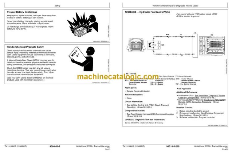
- Prevent Battery Explosions
- Handle Chemical Products Safely
- Decommissioning — Proper Recycling and Disposal of Fluids and Components
- Prepare for Emergencies
- Clean Debris from Machine
- Add Cab Guarding for Special Uses
- Control Pattern
- Use Steps and Handholds Correctly
- Start Only From Operator’s Seat
- Use and Maintain Seat Belt
- Avoid Work Site Hazards
- Prevent Unintended Machine Movement
- Operate Machine Safely
- Avoid Machine Tip Over
- Keep Riders Off Machine
- Use Care When Swinging Machine
- Operate Boom With Care
- Avoid Backover Accidents
- Operating On Slopes
- Add and Operate Attachments Safely
- Travel Safely
- Avoid Power Lines
- Inspect and Maintain ROPS
- Saw Chain Hazard
- Park and Prepare for Service Safely
- Service Machines Safely
- Service Cooling System Safely
- Service Accumulator Systems Safely
- Remove Paint Before Welding or Heating
- Make Welding Repairs Safely
- Drive Metal Pins Safely
- Chain Shot Guard Inspection
- Diagnostic Trouble Codes (DTCs)
- Engine Control Unit (ECU) Diagnostic Trouble Codes
- Diagnostic Trouble Codes (DTCs)
- 000107.00 — Engine Air Filter Extremely Restricted
- 000107.15 — Engine Air Filter is Restricted
- 000107.16 — Engine Air Filter Very Restricted
- 000237.02 — Vehicle Identification Conflict
- 000237.13 — Vehicle Identification Fault
- 000237.31 — Communication Fault
- 001321.05 — Starter Relay Open Circuit
- 001321.16 — Too Long to Start
- 001321.31 — Starter Solenoid Open Circuit
- 003587.05 — Ether Starting Aid Circuit Fault
- 003587.06 — Ether Starting Aid Circuit Fault
- 003587.11 — Ether Starting Aid Circuit Fault
- Hydraulic Motor Controller (HMC) Diagnostic Trouble Codes
- Diagnostic Trouble Codes (DTCs)
- 000158.03 — System Voltage
- 000158.04 — System Voltage
- 000168.03 — Unswitched Power Circuit Fault
- 000168.04 — Unswitched Power Circuit Fault
- 000237.02 — VIN Mismatch
- 000237.13 — VIN Fault
- 000237.31 — VIN Comm Error
- 000629.12 — Watchdog Time Out
- 000639.12 — CAN 1 Failure
- 000639.13 — CAN 1 Bus Off
- 001083.03 — Platform Roll Sensor
- 001083.04 — Platform Roll Sensor
- 001084.03 — Platform Pitch Sensor
- 001084.04 — Platform Pitch Sensor
- 002000.09 — CAN Comm Lost From ECU
- 002030.09 — CAN Comm Lost From VCU
- 002038.09 — CAN Comm Lost From PDU
- 002039.09 — CAN Comm Lost From ACR
- 002046.09 — CAN Comm Lost From HPC
- 002049.09 — CAN Comm Lost From ACR
- 002050.09 — CAN Comm Lost From ACL
- 002141.09 — CAN Comm Lost From SSM
- 003509.03 — Sensor Supply #1
- 003509.04 — Sensor Supply #1
- 522363.03 — RH Drive Motor Speed Sensor
- 522363.04 — RH Drive Motor Speed Sensor
- 522363.05 — RH Drive Motor Speed Sensor
- 522381.03 — LH Drive Motor Speed Sensor
- 522381.04 — LH Drive Motor Speed Sensor
- 522381.05 — LH Drive Motor Speed Sensor
- 523577.03 — LH Motor Control Valve
- 523577.04 — LH Motor Control Valve
- 523577.05 — LH Motor Control Valve
- 523577.06 — LH Motor Control Valve
- 523578.03 — RH Motor Control Valve
- 523578.04 — RH Motor Control Valve
- 523578.05 — RH Motor Control Valve
- 523578.06 — RH Motor Control Valve
- 523821.14 — Controller Mismatch
- 524265.02 — Checksum Error
- Hydraulic Pump Controller (HPC) Diagnostic Trouble Codes
- Diagnostic Trouble Codes (DTCs)
- 000158.03 — System Voltage
- 000158.04 — System Voltage
- 000168.03 — Unswitched Power Circuit Fault
- 000168.04 — Unswitched Power Circuit Fault
- 000237.02 — VIN Mismatch
- 000237.13 — VIN Fault
- 000237.31 — VIN Comm Error
- 000619.03 — Park Brake Valve
- 000619.05 — Park Brake Valve
- 000619.06 — Park Brake Valve
- 000629.12 — Watchdog Time Out
- 000639.12 — CAN 1 Failure
- 000639.14 — CAN 1 Bus Off
- 000907.07 — LH Motor Speed
- 000908.07 — RH Motor Speed
- 001231.12 — CAN 2 Failure
- 001231.14 — CAN 2 Bus Off
- 002000.09 — CAN Comm Lost From ECU
- 002019.09 — CAN Comm Lost From HMC
- 002030.09 — CAN Comm Lost From VCU
- 002038.09 — CAN Comm Lost From PDU
- 002049.09 — CAN Comm Lost From ACR
- 002050.09 — CAN Comm Lost From ACL
- 002141.09 — CAN Comm Lost From SSM
- 003359.03 — Transmission Oil Filter Switch
- 003359.16 — Transmission Oil Filter Switch
- 003509.03 — Sensor Supply #1
- 003509.04 — Sensor Supply #1
- 520570.03 — Transmission Cold Start Valve
- 520570.05 — Transmission Cold Start Valve
- 520570.06 — Transmission Cold Start Valve
- 521730.03 — LH Drive Forward Press Sensor
- 521730.04 — LH Drive Forward Press Sensor
- 521730.16 — LH Drive Forward Press Sensor
- 521732.03 — LH Drive Reverse Press Sensor
- 521732.04 — LH Drive Reverse Press Sensor
- 521732.16 — LH Drive Reverse Press Sensor
- 521733.03 — RH Drive Forward Press Sensor
- 521733.04 — RH Drive Forward Press Sensor
- 521733.16 — RH Drive Forward Press Sensor
- 521734.03 — RH Drive Reverse Press Sensor
- 521734.04 — RH Drive Reverse Press Sensor
- 521734.16 — RH Drive Reverse Press Sensor
- 522078.04 — Transmission Charge Filter Switch
- 522078.16 — Transmission Charge Filter Switch
- 522444.00 — Transmission Charge Press Sensor
- 522444.01 — Transmission Charge Press Sensor
- 522444.03 — Transmission Charge Press Sensor
- 522444.04 — Transmission Charge Press Sensor
- 522447.03 — RH Track FWD Control
- 522447.04 — RH Track FWD Control
- 522447.05 — RH Track FWD Control
- 522447.06 — RH Track FWD Control
- 522447.15 — RH Track Calibration Fault
- 522447.16 — RH Track Calibration Fault
- 522447.18 — RH Track Calibration Fault
- 522448.03 — RH Track REV Control
- 522448.04 — RH Track REV Control
- 522448.05 — RH Track REV Control
- 522448.06 — RH Track REV Control
- 522448.15 — RH Track REV Calibration Fault
- 522448.16 — RH Track REV Calibration Fault
- 522448.18 — RH Track REV Calibration Fault
- 522449.03 — LH Track FWD Control
- 522449.04 — LH Track FWD Control
- 522449.05 — LH Track FWD Control
- 522449.06 — LH Track FWD Control
- 522449.15 — LH Track Calibration Fault
- 522449.16 — LH Track Calibration Fault
- 522449.18 — LH Track Calibration Fault
- 522450.03 — LH Track REV Control
- 522450.04 — LH Track REV Control
- 522450.05 — LH Track REV Control
- 522450.06 — LH Track REV Control
- 522450.15 — LH Track REV Calibration Fault
- 522450.16 — LH Track REV Calibration Fault
- 522450.18 — LH Track REV Calibration Fault
- 522810.00 — Transmission Park Brake Press Sensor
- 522810.01 — Transmission Park Brake Press Sensor
- 522810.03 — Transmission Park Brake Press Sensor
- 522810.04 — Transmission Park Brake Press Sensor
- 523440.04 — Unswitched Power
- 523821.14 — Controller Mismatch
- 523821.31* — Controller Mismatch
- 524233.07 — Hydrostatic Drive System
- 524265.02 — Checksum Error
- Left Armrest Controller (ACL) Diagnostic Trouble Codes
- Diagnostic Trouble Codes (DTCs)
- 000158.03 — System Voltage
- 000158.04 — System Voltage
- 000168.03 — Unswitched Power Circuit Fault
- 000168.04 — Unswitched Power Circuit Fault
- 000237.02 — VIN Mismatch
- 000237.13 — VIN Fault
- 000237.31 — VIN Comm Error
- 000629.12 — Watchdog Time Out
- 000629.13 — Controller Fault
- 000639.12 — CAN 1 Failure
- 000639.13 — CAN 1 Bus Off
- 002030.09 — CAN Comm Lost From ACR
- 002034.09 — CAN Comm Lost From HCU
- 002046.09 — CAN Comm Lost From HPC
- 002049.09 — CAN Comm Lost From VCU
- 002697.03 — LH Joystick X-Axis Signal
- 002697.04 — LH Joystick X-Axis Signal
- 002698.03 — LH Joystick Y-Axis Signal
- 002698.04 — LH Joystick Y-Axis Signal
- 002722.04 — LH Joystick Button 1
- 002723.04 — LH Joystick Button 2
- 002724.04 — LH Joystick Button 3
- 002725.04 — LH Joystick Button 4
- 002726.04 — LH Joystick Button 5
- 002727.04 — LH Joystick Button 6
- 002728.04 — LH Joystick Button 7
- 003976.06 — Cab Dome Light
- 003509.03 — Sensor Supply #1
- 003509.04 — Sensor Supply #1
- 004494.03 — LH Pedal Signal A
- 004494.04 — LH Pedal Signal A
- 004498.03 — LH Pedal Signal B
- 004498.04 — LH Pedal Signal B
- 523440.04 — Unswitched Power
- 523821.14 — Controller Mismatch
- 524265.02 — Checksum Error
- Right Armrest Controller (ACR) Diagnostic Trouble Codes
- Diagnostic Trouble Codes (DTCs)
- 000158.03 — System Voltage
- 000158.04 — System Voltage
- 000168.03 — Unswitched Power Circuit Fault
- 000168.04 — Unswitched Power Circuit Fault
- 000237.02 — VIN Mismatch
- 000237.13 — VIN Fault
- 000237.31 — VIN Comm Error
- 000629.12 — Watchdog Time Out
- 000920.03 — Cab Alarm
- 000920.05 — Cab Alarm
- 000920.06 — Cab Alarm
- 002034.09 — CAN Comm Lost From HCU
- 002046.09 — CAN Comm Lost From HPC
- 002030.09 — CAN Comm Lost From VCU
- 002050.09 — CAN Comm Lost From ACL
- 002251.09 — CAN Comm Lost From JDL
- 002660.03 — RH Joystick X-Axis Signal
- 002660.04 — RH Joystick X-Axis Signal
- 002661.03 — RH Joystick Y-Axis Signal
- 002661.04 — RH Joystick Y-Axis Signal
- 002685.04 — RH Joystick Button 1
- 002686.04 — RH Joystick Button 2
- 002687.04 — RH Joystick Button 3
- 002688.04 — RH Joystick Button 4
- 002689.04 — RH Joystick Button 5
- 002690.04 — RH Joystick Button 6
- 002691.04 — RH Joystick Button 7
- 002734.03 — RH Pedal Signal A
- 002734.04 — RH Pedal Signal A
- 002735.03 — RH Pedal Signal B
- 002735.04 — RH Pedal Signal B
- 003416.03 — Cab Door Switch
- 003509.03 — Sensor Supply #1
- 003509.04 — Sensor Supply #1
- 522873.02 — Harvester Mode Control Voltage Levels Incorrect
- 003976.03* — Cab Dome Lamp
- 523440.04 — Unswitched Power
- 523821.14 — Controller Mismatch
- 524265.02 — Checksum Error
- Sealed Switch Module (SSM) Diagnostic Trouble Codes
- Diagnostic Trouble Codes (DTCs)
- 000629.12 — Watchdog Time Out
- 002030.09 — CAN Comm Lost From VCU
- 002049.09 — CAN Comm Lost From ACR
- 002634.04 — SSM Ignition Relay
- 002634.05 — SSM Ignition Relay
- 520752.04 — SSM Button 17
- 520752.09 — SSM Button 17
- 520753.04 — SSM Button 18
- 520753.09 — SSM Button 18
- 520754.04 — SSM Button 19
- 520754.09 — SSM Button 19
- 520755.04 — SSM Track Speed Raise
- 520755.09 — Track Speed Raise
- 523335.04 — SSM Track Speed Lower
- 523335.09 — SSM Track Speed Lower
- 523336.04 — SSM Hyd Fan Reverse
- 523336.09 — SSM Hyd Fan Reverse
- 523338.04 — SSM Travel Alarm Cancel
- 523338.09 — SSM Travel Alarm Cancel
- 523339.04 — SSM Engine Service Lights
- 523339.09 — SSM Engine Service Lights
- 523340.04 — SSM Forward Work Lights
- 523340.09 — SSM Forward Work Lights
- 523849.04 — SSM Hyd Speed Lower
- 523849.09 — SSM Hyd Speed Lower
- 523850.04 — SSM Enclosure Lower
- 523850.09 — SSM Enclosure Lower
- 523852.04 — SSM Engine Speed Lower
- 523852.09 — SSM Engine Speed Lower
- 523854.04 — SSM Button 13
- 523854.09 — SSM Button 13
- 523855.04 — SSM Saw Pilot Enable
- 523855.09 — SSM Saw Pilot Enable
- 523856.04 — SSM Hyd Speed Raise
- 523856.09 — SSM Hyd Speed Raise
- 523857.04 — SSM Enclosure Raise
- 523857.09 — SSM Enclosure Raise
- 523858.04 — SSM Engine Speed Raise
- 523858.09 — SSM Engine Speed Raise
- 523860.04 — SSM Swing Brake
- 523860.09 — SSM Swing Brake
- 523861.04 — SSM Button 7
- 523861.09 — SSM Button 7
- 523862.04 — SSM Master Speed Select
- 523862.09 — SSM Master Speed Select
- 523863.04 — SSM Hydraulic Enable
- 523863.09 — SSM Hydraulic Enable
- 523864.04 — SSM Auto Idle
- 523864.09 — SSM Auto Idle
- 523865.04 — SSM Button 3
- 523865.09 — SSM Button 3
- 523867.04 — SSM Ignition Off
- 523867.09 — SSM Ignition Off
- 523868.04 — SSM Ignition/Start
- 523868.09 — SSM Ignition/Start
- Vehicle Control Unit (VCU) Diagnostic Trouble Codes
- Diagnostic Trouble Codes (DTCs)
- 000096.03 — Fuel Level Sensor
- 000096.04 — Fuel Level Sensor
- 000158.03 — System Voltage
- 000158.04 — System Voltage
- 000237.02 — VIN Mismatch
- 000237.13 — VIN Fault
- 000237.31 — VIN Comm Error
- 000628.12 — Control Unit Programming
- 000629.12 — Watchdog Time Out
- 000629.13 — Controller Fault
- 000639.12 — Can 1 Failure
- 000639.14 — Can 1 Bus Off
- 000785.03 — TFB Att Pump Unloader Valve
- 000785.05 — TFB Att Pump Unloader Valve
- 000785.06 — TFB Att Pump Unloader Valve
- 000875.01 — AC High / Low Press Sensor
- 000875.04 — AC High / Low Press Sensor
- 000877.04 — AC Freeze Sensor
- 001083.03 — Platform Roll Sensor
- 001083.04 — Platform Roll Sensor
- 001084.03 — Platform Pitch Sensor
- 001084.04 — Platform Pitch Sensor
- 001231.12 — Can 2 Failure
- 001231.14 — Can 2 Bus Off
- 001550.03 — A/C Compressor Clutch
- 001550.05 — A/C Compressor Clutch
- 001550.06 — A/C Compressor Clutch
- 001638.00 — Hydraulic Oil Temperature Sensor
- 001638.03 — Hydraulic Oil Temperature Sensor
- 001638.04 — Hydraulic Oil Temperature Sensor
- 001639.08 — Hydraulic Fan Speed Sensor Signal Missing
- 001713.16 — Hydraulic Oil Filter Restricted
- 001907.03 — RCS Enable Control Valve
- 001907.05 — RCS Enable Control Valve
- 001907.06 — RCS Enable Control Valve
- 002000.09 — CAN Comm Lost From ECU
- 002019.09 — CAN Comm Lost From HMC
- 002049.09 — CAN Comm Lost From ACR
- 002050.09 — CAN Comm Lost From ACL
- 002141.09 — CAN Comm Lost From SSM
- 002351.03 — Upper Cab Light 1-4
- 002351.05 — Upper Cab Light 1-4
- 002351.06 — Upper Cab Light 1-4
- 002355.03 — Upper Cab Light 5-6
- 002355.05 — Upper Cab Light 5-6
- 002355.06 — Upper Cab Light 5-6
- 002357.03 — Leveler Light
- 002357.05 — Leveler Light
- 002357.06 — Leveler Light
- 002359.03 — Enclosure Lights 1-4
- 002359.05 — Enclosure Lights 1-4
- 002359.06 — Enclosure Lights 1-4
- 002361.03 — Service Lights 3-4
- 002361.05 — Service Lights 3-4
- 002361.06 — Service Lights 3-4
- 002363.03 — Service Lights 1-2
- 002363.05 — Service Lights 1-2
- 002363.06 — Service Lights 1-2
- 002365.03 — Side Cab Light 1-2
- 002365.05 — Side Cab Light 1-2
- 002365.06 — Side Cab Light 1-2
- 002602.01 — Hydraulic Oil Level Switch
- 002602.03 — Hydraulic Oil Level Switch
- 002602.04 — Hydraulic Oil Level Switch
- 002602.12 — Hydraulic Oil Level Switch
- 003413.04 — Engine Enclosure Limit Switch
- 003419.04 — Rear Door Limit Switch
- 003509.03 — Sensor Supply # 1
- 003509.04 — Sensor Supply # 1
- 003510.03 — Sensor Supply # 2
- 003510.04 — Sensor Supply # 2
- 516395.03 — Saw / Harv Pump PL Press Sensor
- 516395.04 — Saw / Harv Pump PL Press Sensor
- 520571.03 — Primary Pump Unloader Valve
- 520571.05 — Primary Pump Unloader Valve
- 520571.06 — Primary Pump Unloader Valve
- 520804.00 — LH Hydrostatic Motor Oil Temperature Sensor
- 520804.03 — LH Hydrostatic Motor Oil Temperature Sensor
- 520804.04 — LH Hydrostatic Motor Oil Temperature Sensor
- 520805.00 — RH Hydrostatic Motor Oil Temperature Sensor
- 520805.03 — RH Hydrostatic Motor Oil Temperature Sensor
- 520805.04 — RH Hydrostatic Motor Oil Temperature Sensor
- 520856.03 — TFB Saw Cooler Control Valve
- 520856.04 — TFB Saw Cooler Control Valve
- 520856.05 — TFB Saw Cooler Control Valve
- 520856.06 — TFB Saw Cooler Control Valve
- 521731.03 — Main Pump PX Press Sensor
- 521731.04 — Main Pump PX Press Sensor
- 521731.16 — Main Pump PX Press Sensor
- 521735.03 — Attach / Harv Pump A PX Press Sensor
- 521735.04 — Attach / Harv Pump A PX Press Sensor
- 521735.16 — Attach / Harv Pump A PX Press Sensor
- 521736.03 — Main Pump PS Press Sensor
- 521736.04 — Main Pump PS Press Sensor
- 521736.16 — Main Pump PS Press Sensor
- 521736.18 — Main Pump PS Press Sensor
- 521737.03 — Valve Gallery Return Press Sensor
- 521737.04 — Valve Gallery Return Press Sensor
- 521737.16 — Valve Gallery Return Press Sensor
- 521738.03 — HST Case Press Sensor
- 521738.04 — HST Case Press Sensor
- 521738.16 — HST Case Press Sensor
- 521739.03 — Main Pump PL Press Sensor
- 521739.04 — Main Pump PL Press Sensor
- 521973.04 — Cab Lighting Wakeup Switch
- 521974.04 — Engine Bay Lighting Wakeup Switch
- 522179.03 — Harvester Head Rotate CCW Control Valve
- 522179.04 — Harvester Head Rotate CCW Control Valve
- 522179.05 — Harvester Head Rotate CCW Control Valve
- 522179.06 — Harvester Head Rotate CCW Control Valve
- 522180.03 — Harvester Head Rotate CW Control Valve
- 522180.04 — Harvester Head Rotate CW Control Valve
- 522180.05 — Harvester Head Rotate CW Control Valve
- 522180.06 — Harvester Head Rotate CW Control Valve
- 522340.03 — Enclosure Pump Relay
- 522340.05 — Enclosure Pump Relay
- 522340.06 — Enclosure Pump Relay
- 522379.03 — Swing Brake Control Valve
- 522379.05 — Swing Brake Control Valve
- 522379.06 — Swing Brake Control Valve
- 522439.03 — Cooler Bypass Valve
- 522439.05 — Cooler Bypass Valve
- 522439.06 — Cooler Bypass Valve
- 522447.03 — RH Track FWD Control Valve
- 522447.04 — RH Track FWD Control Valve
- 522447.05 — RH Track FWD Control Valve
- 522447.06 — RH Track FWD Control Valve
- 522448.03 — RH Track REV Control Valve
- 522448.04 — RH Track REV Control Valve
- 522448.05 — RH Track REV Control Valve
- 522448.06 — RH Track REV Control Valve
- 522449.03 — LH Track REV Control Valve
- 522449.04 — LH Track REV Control Valve
- 522449.05 — LH Track REV Control Valve
- 522449.06 — LH Track REV Control Valve
- 522450.03 — LH Track FWD Control Valve
- 522450.04 — LH Track FWD Control Valve
- 522450.05 — LH Track FWD Control Valve
- 522450.06 — LH Track FWD Control Valve
- 522541.03 — Head Tilt Out Control Valve
- 522541.04 — Head Tilt Out Control Valve
- 522541.05 — Head Tilt Out Control Valve
- 522541.06 — Head Tilt Out Control Valve
- 522542.03 — Head Tilt In Control Valve
- 522542.04 — Head Tilt In Control Valve
- 522542.05 — Head Tilt In Control Valve
- 522542.06 — Head Tilt In Control Valve
- 522543.03 — Hoist Boom Lower Control Valve
- 522543.04 — Hoist Boom Lower Control Valve
- 522543.05 — Hoist Boom Lower Control Valve
- 522543.06 — Hoist Boom Lower Control Valve
- 522544.03 — Hoist Boom Raise Control Valve
- 522544.04 — Hoist Boom Raise Control Valve
- 522544.05 — Hoist Boom Raise Control Valve
- 522544.06 — Hoist Boom Raise Control Valve
- 522548.03 — Travel Hi/Low Motor Pilot Valve
- 522548.05 — Travel Hi/Low Motor Pilot Valve
- 522548.06 — Travel Hi/Low Motor Pilot Valve
- 522608.03 — TFB Saw Control Valve
- 522608.04 — TFB Saw Control Valve
- 522608.05 — TFB Saw Control Valve
- 522608.06 — TFB Saw Control Valve
- 522833.03 — RCS Retract Control Valve
- 522833.04 — RCS Retract Control Valve
- 522833.05 — RCS Retract Control Valve
- 522833.06 — RCS Retract Control Valve
- 522834.03 — RCS Extend Control Valve
- 522834.04 — RCS Extend Control Valve
- 522834.05 — RCS Extend Control Valve
- 522834.06 — RCS Extend Control Valve
- 523196.03 — Enclosure Directional Valve
- 523196.05 — Enclosure Directional Valve
- 523196.06 — Enclosure Directional Valve
- 523217.03 — Valve Power #3
- 523217.04 — Valve Power #3
- 523218.03 — Valve Power #2
- 523218.04 — Valve Power #2
- 523219.03 — Valve Power #1
- 523219.04 — Valve Power #1
- 523294.03 — Saw / Harv Pump B PX Press Sensor
- 523294.04 — Saw / Harv Pump B PX Press Sensor
- 523294.16 — Saw / Harv Pump B PX Press Sensor
- 523325.03 — Main Pump Displacement Sensor
- 523325.04 — Main Pump Displacement Sensor
- 523493.04 — Hydraulic Case Filter Switch
- 523493.16 — Hydraulic Case Filter Switch
- 523541.03 — Motion Alarm
- 523541.05 — Motion Alarm
- 523541.06 — Motion Alarm
- 523911.03 — Hydraulic Power Mgt Valve
- 523911.04 — Hydraulic Power Mgt Valve
- 523911.05 — Hydraulic Power Mgt Valve
- 523911.06 — Hydraulic Power Mgt Valve
- 523916.03 — Hydraulic Oil Filter Sensor
- 523916.04 — Hydraulic Oil Filter Sensor
- 523930.03 — Stick Boom In Control Valve
- 523930.04 — Stick Boom In Control Valve
- 523930.05 — Stick Boom In Control Valve
- 523930.06 — Stick Boom In Control Valve
- 523931.03 — Stick Boom Out Control Valve
- 523931.04 — Stick Boom Out Control Valve
- 523931.05 — Stick Boom Out Control Valve
- 523931.06 — Stick Boom Out Control Valve
- 523932.03 — Swing CCW Control Valve
- 523932.04 — Swing CCW Control Valve
- 523932.05 — Swing CCW Control Valve
- 523932.06 — Swing CCW Control Valve
- 523933.03 — Swing CW Control Valve
- 523933.04 — Swing CW Control Valve
- 523933.05 — Swing CW Control Valve
- 523933.06 — Swing CW Control Valve
- 523938.03 — LH Level Extend Control Valve
- 523938.04 — LH Level Extend Control Valve
- 523938.05 — LH Level Extend Control Valve
- 523938.06 — LH Level Extend Control Valve
- 523939.03 — RH Level Extend Control Valve
- 523939.04 — RH Level Extend Control Valve
- 523939.05 — RH Level Extend Control Valve
- 523939.06 — RH Level Extend Control Valve
- 523940.03 — LH Level Retract Control Valve
- 523940.04 — LH Level Retract Control Valve
- 523940.05 — LH Level Retract Control Valve
- 523940.06 — LH Level Retract Control Valve
- 523941.03 — RH Level Retract Control Valve
- 523941.04 — RH Level Retract Control Valve
- 523941.05 — RH Level Retract Control Valve
- 523941.06 — RH Level Retract Control Valve
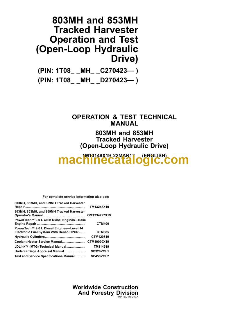
- 523983.03 — Hydraulic Fan Control Valve
- 523983.04 — Hydraulic Fan Control Valve
- 523983.05 — Hydraulic Fan Control Valve
- 523983.06 — Hydraulic Fan Control Valve
- 524124.03 — Hydraulic Fan Control Valve
- 524124.05 — Hydraulic Fan Control Valve
- 524124.06 — Hydraulic Fan Control Valve
- 524265.02 — Checksum Error
- Primary Display Unit (PDU) Diagnostic Trouble Codes
- Diagnostic Trouble Codes (DTCs)
- 000609.12 — Internal Failure
- 001386.00 — Display Temperature Above Normal
- 001386.01 — Display Temperature Below Normal
- 002049.09 — CAN Comm Lost From ACR
- 003599.02 — 3.3V Power Supply
- 521780.12 — USB Input Over Current
- 523436.14 — Watchdog Timeout
- 523438.31 — Internal Memory Failure
- 523651.02 — Internal Memory Failure
- 523773.03 — CAN HIGH
- 523773.04 — CAN HIGH
- 523774.03 — CAN LOW
- 523774.04 — CAN LOW
- 524050.12 — Real-Time Clock Failure
- 524076.10 — Menu Select Button Stuck
- 524077.10 — Back Key Button Stuck
- 524078.10 — Button 2 Stuck
- 524080.10 — Button 1 Stuck
- 524082.10 — Information Button Stuck
- 524094.10 — Down Arrow Button Stuck
- 524095.10 — Up Arrow Button Stuck
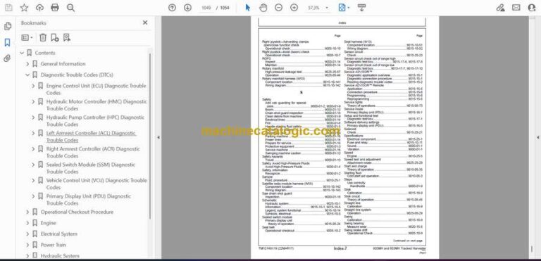
- Operational Checkout Procedure
- Operational Checkout Procedure
- Operational Checkout
- Diagnostic Trouble Code Check
- Ignition OFF, Engine OFF Checks
- Ignition On, Engine Off Checks
- Operational Checks—Ignition ON, Engine ON Checks
- Cycle Times
- Engine
- Theory of Operation
- John Deere Engine
- Engine Identification
- Cold Start Aid Operation—Starting Fluid
- Cold Start Aid Operation—Diesel Fired Coolant Heater (DFCH)—(if equipped)
- System Diagrams
- John Deere Engine
- Engine Cooling System Component Location
- Engine Fuel System Component Location
- Engine Intake and Exhaust System Component Location
- Diesel Fired Coolant Heater System Component Location
- Diagnostic Information
- John Deere Engine Diagnostic Information
- Tests
- Fluid Sampling Procedure—If Equipped
- Engine Speed Test and Auto Idle Check
- Fuel Line Leakage Test
- Air Filter Restriction Indicator Switch Test
- Air Intake System Leakage Test
- Electrical System
- Theory of Operation
- Controller Area Network (CAN) Circuit Theory of Operation
- Engine Control Unit (ECU) Circuit Theory of Operation
- Vehicle Control Unit (VCU) Circuit Theory of Operation
- Primary Display Unit (PDU) and Sealed Switch Module (SSM) Circuits Theory of Operation
- Right Armrest Controller (ACR) and Left Armrest Controller (ACL) Circuits Theory of Operation
- Start and Charge Circuits Theory of Operation
- Cold Start Circuit Theory of Operation—(If Equipped)
- Diesel Fired Coolant Heater (DFCH) Circuit Theory of Operation—If Equipped
- Hydraulics Enable and Disable Circuit Theory of Operation
- Boom, Stick, and Swing Circuits Theory of Operation
- Rapid Cycle System (RCS) Circuit Theory of Operation
- Attachment Control Circuit Theory of Operation
- TimberRite™ System Control Circuit Theory of Operation
- TimberRite™ Joystick Control Circuit Theory of Operation
- Travel Control Circuit Theory of Operation
- Fan Control Circuit Theory of Operation
- Enclosure Door Control Circuit Theory of Operation
- Service and Work Lights Circuits Theory of Operation
- Air Conditioning and Heater Circuit Theory of Operation
- JDLink™ Circuit Theory of Operation
- System Diagrams
- Electrical Diagram Information
- Electrical Schematic Symbols
- Publication Terminology and Machine Wiring Harness Tag Cross Reference Table
- Fuse and Relay Specifications
- System Functional Schematic, Component Location, and Wiring Diagram Master Legend
- System Functional Schematic
- Load Center Power Harness (W1) Wiring Diagram
- Load Center Power Interface Harness (W2) Wiring Diagram
- Load Center Ground Cable (W3) Wiring Diagram
- Engine Enclosure Door Power Cable (W4) Wiring Diagram
- Engine Enclosure Door Ground Cable (W5) Wiring Diagram
- Engine Ground Strap (W6) Wiring Diagram
- Cab Front Work Light Harness (W7) Component Location
- Cab Front Work Light Harness (W7) Wiring Diagram
- Upper Cab Harness (W8) Component Location
- Upper Cab Harness (W8) Wiring Diagram
- Right Console Harness (W9) Component Location
- Right Console Harness (W9) Wiring Diagram
- Travel Pedal Harness (W10) Component Location
- Travel Pedal Harness (W10) Wiring Diagram
- Vehicle Control Unit (VCU) Power Cable (W11) Component Location
- Vehicle Control Unit (VCU) Power Cable (W11) Wiring Diagram
- Heating and Air Conditioning Harness (W12) Component Location
- Heating and Air Conditioning Harness (W12) Wiring Diagram
- Seat Harness (W13) Component Location
- Seat Harness (W13) Wiring Diagram
- Load Center Harness (W14) Component Location
- Load Center Harness (W14) Wiring Diagram
- TimberRite™ System Harness (W15) Component Location
- TimberRite™ System Harness (W15) Wiring Diagram
- TimberRite™ Key Switch Harness (W16) Component Location
- TimberRite™ Key Switch Harness (W16) Wiring Diagram
- TimberRite™ Left Joystick Harness (W19) Component Location
- TimberRite™ Left Joystick Harness (W19) Wiring Diagram
- TimberRite™ Right Joystick Harness (W20) Component Location
- TimberRite™ Right Joystick Harness (W20) Wiring Diagram
- Front Chassis Harness (W22) Component Location
- Front Chassis Harness (W22) Wiring Diagram
- TimberRite™ USB Harness (W23) Component Location
- TimberRite™ USB Harness (W23) Wiring Diagram—Side Panel
- Front Center Chassis Harness (W24) Component Location
- Front Center Chassis Harness (W24) Wiring Diagram
- Front Right Chassis Harness (W25) Component Location
- Front Right Chassis Harness (W25) Wiring Diagram
- Hydraulic Oil Fill Pump Power Cable (W26) Component Location—If Equipped
- Hydraulic Oil Fill Pump Power Cable (W26) Wiring Diagram—If Equipped
- Hydraulic Oil Fill Pump Ground Cable (W27) Component Location—If Equipped
- Hydraulic Oil Fill Pump Ground Cable (W27) Wiring Diagram—If Equipped
- Center Chassis Harness (W28) Component Location
- Center Chassis Harness (W28) Wiring Diagram
- Fuel Level Sensor Harness (W30) Component Location
- Fuel Level Sensor Harness (W30) Wiring Diagram
- Rear Chassis Harness (W31) Component Location
- Rear Chassis Harness (W31) Wiring Diagram
- Attachment Harness (W32) Component Location
- Attachment Harness (W32) Wiring Diagram
- Diesel Fired Coolant Heater (DFCH) Harness (W34) Component Location—If Equipped
- Diesel Fired Coolant Heater (DFCH) Harness (W34) Wiring Diagram—If Equipped
- Engine Harness (W36) Component Location
- Engine Harness (W36) Wiring Diagram
- Fan, Air Filter, and Travel Alarm Harness (W37) Component Location
- Fan, Air Filter, and Travel Alarm Harness (W37) Wiring Diagram
- Harvester Head Harness (W41) Component Location
- Harvester Head Harness (W41) Wiring Diagram
- Rotary Manifold Harness (W53) Component Location
- Rotary Manifold Harness (W53) Wiring Diagram
- Satellite Radio Module Harness (W55) Component Location—If Equipped
- Satellite Radio Module Harness (W55) Wiring Diagram—If Equipped
- Radio USB and Microphone Harness (W56) Component Location
- Radio USB and Microphone Harness (W56) Wiring Diagram
- Radio USB Cable (W57) Component Location—If Equipped
- Radio USB Cable (W57) Wiring Diagram—If Equipped
- JDLink™ Harnesses (W6002 and W6003) Component Location
- JDLink™ Modular Telematics Gateway (MTG) Harness (W6002) Wiring Diagram
- JDLink™ Satellite (SAT) Harness (W6003) Wiring Diagram
- Diagnostic Information
- Service ADVISOR™ Diagnostic Application
- Service ADVISOR™ Connection Procedure
- Reading Diagnostic Trouble Codes (DTCs) With Service ADVISOR™ Diagnostic Application
- Service ADVISOR™ Remote (SAR) Application
- Service ADVISOR™ Remote (SAR) Connection Procedure
- JDLink™ Connection Procedure—If Equipped
- Intermittent Diagnostic Trouble Code (DTC) Diagnostics
- Monitor Operation
- Service Mode
- Diagnostics—Clear Stored Diagnostic Trouble Codes (DTCs)
- Diagnostics—Engine Readings for Voltages and Currents
- Diagnostics—Machine Readings
- Diagnostics—Software Delivery Settings
- Diagnostics—Electronic Controller Identification
- Setup—Antitheft/Security
- Setup—Restore Factory Default Settings
- Setup—Fan Control
- Setup—Machine Configuration
- Setup—Calibration
- Diagnostic Test Box
- Setup and Functional Test
- Two Wire Sensor Circuit Check—Out of Range High
- Two Wire Sensor Circuit Check—Out of Range Low
- Three Wire Sensor Circuit Check—Out of Range High
- Three Wire Sensor Circuit Check—Out of Range Low
- Tests
- Electrical Component Specifications
- Electrical Component Checks
- Controller Area Network (CAN) Diagnostics
- Joystick X and Y Axis Diagnostic Procedure
- Joystick Switch Diagnostic Procedure
- Travel Pedal Sensor Diagnostic Procedure
- Connector Terminal Test Diagnostic Procedure
- Power Train
- Theory of Operation
- Track Adjuster and Recoil Spring Operation
- Travel Gear Case Operation
- Diagnostic Information
- Noisy or Loose Track Chain
- Noisy or Loose Track Chain Diagnostic Procedure
- Tight Track Chain
- Tight Track Chain Diagnostic Procedure
- Frequent Track Chain Sag Adjustment Required
- Frequent Track Chain Sag Adjustment Required Diagnostic Procedure
- Excessive Oil Leakage From Front Idler, Track Rollers, or Carrier Rollers
- Frequent Track Chain Sag Adjustment Required Diagnostic Procedure
- Bent Track Shoes
- Bent Track Shoes Diagnostic Procedure
- “Popping” Of Track
- “Popping” Of Track Diagnostic Procedure
- Cracked Track Link
- Cracked Track Link Diagnostic Procedure
- Chipped Track Link Rails
- Chipped Track Link Rails Diagnostic Procedure
- Individual Undercarriage Component Wear
- Individual Undercarriage Component Wear Diagnostic Procedure
- Measure Swing Bearing Wear
- Hydraulic System
- Theory of Operation
- Main Hydraulic System Operation
- Main Pump Operation
- Attachment Pump System Operation
- Main Control Valve Operation
- Auxiliary Control Valve Operation
- Attachment System Operation
- Straight Line System (SLS) Operation
- Pilot System Operation
- Hydraulic Pump Damper Drive Operation
- Swing System Operation
- Rotary Manifold Operation
- Travel Motor Operation
- Fan System Operation
- Enclosure Door System Operation
- Hydraulic System Warm-Up Operation
- Hydraulic Reservoir Operation
- Hydraulic Reservoir Fill Pump Operation
- System Diagrams
- Hydraulic System Schematic
- Hydraulic System Component Location
- Hydraulic Pump System Line Identification
- Travel System Line Identification
- Pilot System Line Identification
- Boom and Stick Line Identification
- Swing System Line Identification
- Hydraulic Oil Cooling System Line Identification
- Enclosure Door System Line Identification
- Hydraulic Reservoir Fill Pump Line Identification
- Diagnostic Information
- Hydraulic Oil Overheats
- Hydraulic Oil Overheats Diagnostic Procedure
- No Hydraulic Functions
- No Hydraulic Functions Diagnostic Procedure
- All Hydraulic Functions Slow
- All Hydraulic Functions Slow Diagnostic Procedure
- Poor Combined Function
- Poor Combined Function Diagnostic Procedure
- Function Does Not Stop When Joystick Released
- Function Does Not Stop When Joystick Released Diagnostic Procedure
- Some Functions Cannot Be Operated, All Others Are Normal
- Some Functions Cannot Be Operated, All Others Are Normal Diagnostic Procedure
- Some Functions Slow, All Others Are Normal
- Some Functions Slow, All Others Are Normal Diagnostic Procedure
- Rapid Cycle System (RCS) Boom Operation is Jerky, Aggressive, “Spongy”, or Drifts
- Rapid Cycle System (RCS) Boom Operation is Jerky, Aggressive, “Spongy”, or Drifts Diagnostic Procedure
- Load Drifts Down When Control Valve is in Neutral Position
- Load Drifts Down When Control Valve is in Neutral Position Diagnostic Procedure
- Load Falls When Control Valve is Actuated to Raise Load With Engine Running at Slow Idle
- Load Falls When Control Valve is Actuated to Raise Load With Engine Running at Slow Idle Diagnostic Procedure
- Swing Speed Slow in Both Directions
- Swing Speed Slow in Both Directions Diagnostic Procedure
- Swing Speed Slow or Does Not Operate in One Direction
- Swing Speed Slow or Does Not Operate in One Direction Diagnostic Procedure
- Upperstructure Drift
- Upperstructure Drift Diagnostic Procedure
- Swing Function Does Not Operate
- Swing Function Does Not Operate Diagnostic Procedure
- Track Will Not Move in One Direction
- Track Will Not Move in One Direction Diagnostic Procedure
- Track Will Not Move in Either Direction
- Track Will Not Move in Either Direction Diagnostic Procedure
- Machine Mistracks at All Speeds in Both Directions
- Machine Mistracks at All Speeds in Both Directions Diagnostic Procedure
- Slow Travel Speed or Low Power
- Slow Travel Speed or Low Power Diagnostic Procedure
- Travel is “Jerky”
- Travel is “Jerky” Diagnostic Procedure
- Machine Will Not Hold Back, Park Brakes Engage and Disengage When Traveling Down an Incline
- Machine Will Not Hold Back, Park Brakes Engage and Disengage When Traveling Down an Incline Diagnostic Procedure
- Machine Will Not Turn Smoothly in One Direction or Park Brake Grabs
- Machine Will Not Turn Smoothly in One Direction or Park Brake Grabs Diagnostic Procedure
- Tests
- General Machine Pressure and Speed Specifications
- JT02156A Digital Pressure/Temperature Analyzer Kit Installation
- Vacuum Pump Installation
- Hydraulic Oil Cleanup Procedure
- Hydraulic Oil Warm-Up Procedure
- Hydraulic System Deaeration
- Hydraulic System Setup Procedure
- Load Sense System Flushing Procedure
- Main Hydraulic Pump Power Control Test and Adjustment
- Main Hydraulic Pump Differential Pressure Test and Adjustment
- Main Hydraulic Pump Case Drain Test
- Attachment Pump Pressure Test and Adjustment
- Attachment Pump System Case Drain Test
- Load Sense System Pressure Test and Adjustment
- Pilot System Pressure Test
- Attachment Rotate Speed Test and Adjustment
- Boom Circuit Pressure Test and Adjustment
- Stick Circuit Pressure Test and Adjustment
- Straight Line System (SLS) Adjustment
- Cylinder Drift Test—Boom and Stick
- Travel Motor Speed Test and Adjustment
- Travel Motor Pressure Test and Adjustment
- Travel Motor Crossover Relief Valve Test and Adjustment
- Travel Motor Case Drain Test
- Park Brake Release Pressure Test and Adjustment
- Park Brake Test
- Park Brake Lock and Unlock Procedure
- Swing Speed Test and Adjustment
- Swing System Pressure Test and Adjustment
- Swing Brake Pressure Test
- Swing Motor Case Drain Test
- Rotary Manifold Pressure Test
- Fan Speed Test
- Fan Motor Case Drain Test
- Hydraulic Oil Cooler Bypass Valve Test
- Miscellaneous
- Theory of Operation
- Fire Suppression System Operation
- System Diagrams
- Fire Suppression System Component Location
- Fire Suppression System Wiring Diagrams
- Heating and Air Conditioning
- Theory of Operation
- Air Conditioning System Cycle of Operation
- System Diagrams
- Heater and Air Conditioning System Component Location
- Diagnostic Information
- Air Conditioning System Does Not Operate
- Air Conditioning System Does Not Operate Diagnostic Procedure
- Air Conditioning Does Not Cool Interior of Cab
- Air Conditioning Does Not Cool Interior of Cab Diagnostic Procedure
- Air Conditioning Runs Constantly, Too Cold
- Air Conditioning Runs Constantly, Too Cold Diagnostic Procedure
- Heater System Does Not Operate
- Heater System Does Not Operate Diagnostic Procedure
- Heater Does Not Warm Interior of Cab
- Heater Does Not Warm Interior of Cab Diagnostic Procedure
- Interior Windows Continue to Fog
- Interior Windows Continue to Fog Using Heater Diagnostic Procedure
- Tests
- R134a Refrigerant Cautions and Proper Handling
- R134a Oil Charge Capacity
- R134a Refrigerant Charge Capacity
- Heater and Air Conditioner Operational Checks
- Visual Inspection of Components
- Air Conditioner Compressor Clutch Test
- R134a Refrigerant Leak Test
- R134a Refrigerant Hoses and Tubing Inspection
- Air Conditioner High/Low Pressure Switch Test
- Air Conditioner Freeze Control Switch Test
- Air Conditioning System Test
- Operating Pressure Diagnostic Chart
- Air Conditioner Compressor Belt Check and Adjustment
John Deere
