Format: PDF (Printable Document)
File Language: English
File Pages: 888
File Size: 30.44 MB (Speed Download Link)
Brand: John Deere
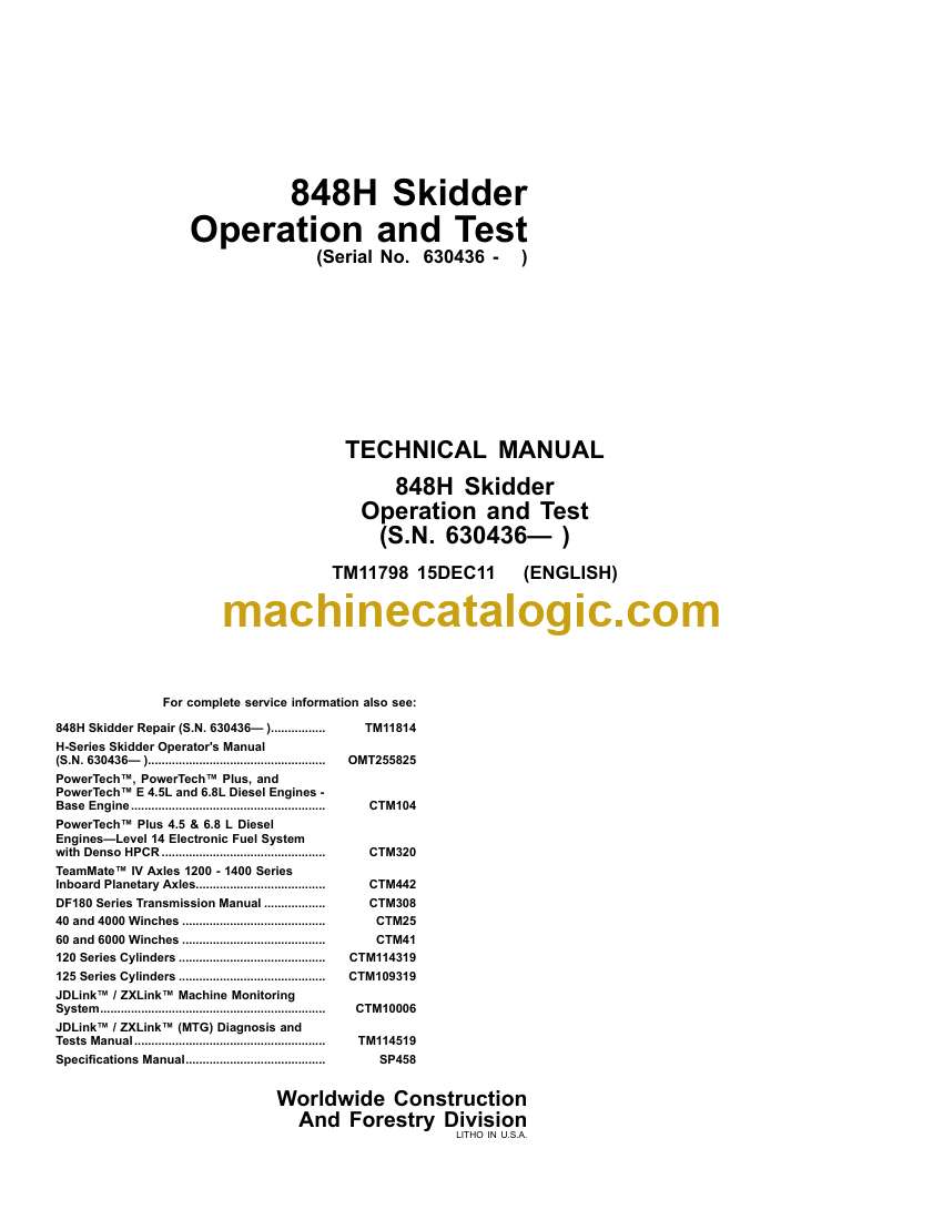
Model: 848H Skidder
Book No: TM11798
Type of Document: Operation and Test Technical Manual
$ 40
