John Deere 850K Crawler Dozer Operation and Test Technical Manual (TM12043)
You’ve got an 850K on a job, operator says “no power, pulls like a dead dog,” and the dash is clean. No codes, just lazy hydraulics and weak travel. Without TM12043 you’re guessing—swapping pumps, blaming turbos, burning hours. With it, you go straight to the right test ports, the right pressures, the right ECU checks. You stop guessing and start proving what’s actually failing.
Key Tasks Covered:
- Verify charge and main hydraulic pressures with the correct ports and spec ranges.
- Run powertrain stall tests and compare to rated torque values.
- Check HST pump and motor control signals from the ECU with pin-by-pin volt/ohm specs.
- Diagnose derate conditions using actual fuel rail pressure and boost targets, not “seat-of-pants.”
- Confirm pilot pressure to blade and ripper circuits before condemning valves or pumps.
Common Questions:
Q: “Machine’s gutless but no codes. Where do I even start?”
A: Follow the powertrain performance test: stall test, record RPM, compare to spec, then check HST control pressures and engine load data. It tells you if it’s engine, hydrostat, or load sensing.
Q: “Hydraulics are slow, pump or valve?”
A: Run the pump flow/pressure test first; if pressure hits spec but functions are slow, the manual walks you to spool leakage and pilot control checks.
Safety Note: Put the blade down, chock it, and bleed system pressure before you crack any line—850K hydraulics will hurt you fast.
📘 Show Index
John Deere 850K Crawler Dozer Index:
- Contents
- General Information
- Safety
- Recognize Safety Information
- Follow Safety Instructions
- Operate Only If Qualified
- Wear Protective Equipment
- Avoid Unauthorized Machine Modifications
- Inspect Machine
- Stay Clear of Moving Parts
- Avoid High-Pressure Fluids
- Beware of Exhaust Fumes
- Prevent Fires
- Prevent Battery Explosions
- Handle Chemical Products Safely
- Dispose of Waste Properly
- Prepare for Emergencies
- Add Cab Guarding For Special Uses
- Use Steps and Handholds Correctly
- Start Only From Operator’s Seat
- Use and Maintain Seat Belt
- Prevent Unintended Machine Movement
- Avoid Work Site Hazards
- Keep Riders Off Machine
- Avoid Backover Accidents
- Avoid Machine Tip Over and Machine Damage
- Add and Operate Attachments Safely
- Park and Prepare for Service Safely
- Service Cooling System Safely
- Remove Paint Before Welding or Heating
- Make Welding Repairs Safely
- Drive Metal Pins Safely
- Diagnostic Trouble Codes (DTC)
- Engine Control Unit (ECU) Diagnostic Trouble Codes
- Engine Control Unit (ECU) Diagnostic Trouble Codes
- 000091.09 — CAN Throttle Missing From VCU
- CAN Throttle Missing From VCU Diagnostic Procedure
- 000647.05 — Fan Drive Solenoid Open or Short to Power
- Fan Drive Solenoid Open or Short to Power Diagnostic Procedure
- 000647.06 — Fan Drive Solenoid Short to Ground
- Fan Drive Solenoid Short to Ground Diagnostic Procedure
- 001321.09 — Starter Signal Missing
- Starter Signal Missing Diagnostic Procedure
- 001321.16 — Engine Starter Engaged Too Long
- Engine Starter Engaged Too Long Diagnostic Procedure
- 001321.31 — Starter Solenoid Open Circuit
- Starter Solenoid Open Circuit Diagnostic Procedure
- 002000.13 — Security Violation
- Security Violation Diagnostic Procedure
- 002030.19 — Communication Error With Source Address 30
- 002031.09 — No CAN Message Received From Source Address 30
- 003353.31 — Alternator Excitation Condition Exists
- Alternator Excitation Condition Exists Diagnostic Procedure
- 005484.05 — Fan Reversing Solenoid Open or Short to Power
- Fan Reversing Solenoid Open or Short to Power Diagnostic Procedu
- 005484.06 — Fan Reversing Solenoid Short to Ground
- Fan Reversing Solenoid Short to Ground Diagnostic Procedure
- Standard Display Monitor (SDM) Diagnostic Trouble Codes
- Standard Display Monitor (SDM) Diagnostic Trouble Codes
- 000096.03 — Fuel Level Sensor Open or Short
- Fuel Level Sensor Open or Short Diagnostic Procedure
- 000096.04 — Fuel Level Sensor Short to Ground
- Fuel Level Sensor Short to Ground Diagnostic Procedure
- 002000.09 — Loss of CAN Communication With ECU
- Loss of CAN Communication With ECU Diagnostic Procedure
- 002030.09 — Loss of CAN Communication With VCU
- Loss of CAN Communication With VCU Diagnostic Procedure
- 002141.09 — Loss of CAN Communication With SSM
- Loss of CAN Communication With SSM Diagnostic Procedure
- Sealed Switch Module (SSM) Diagnostic Trouble Codes
- Sealed Switch Module (SSM) Diagnostic Trouble Codes
- 000444.04 — Invalid Application Configuration
- Invalid Application Configuration Diagnostic Procedure
- 000629.12 — Watchdog Timeout
- Watchdog Timeout Diagnostic Procedure
- 000639.12 — Lost CAN Message
- Lost CAN Message Diagnostic Procedure
- 000639.14 — CAN Bus Off
- CAN Bus Off Diagnostic Procedure
- 002033.09 — No CAN Messages
- No CAN Messages Diagnostic Procedure
- 002634.04 — Ignition Relay Short to Ground
- Ignition Relay Short to Ground Diagnostic Procedure
- 002634.05 — Ignition Relay Open
- Ignition Relay Open Diagnostic Procedure
- 520752.04 — Keypad 7 Button Stuck
- Keypad 7 Button Stuck Diagnostic Procedure
- 520752.09 — No Message For Keypad 7 Button
- No Message For Keypad 7 Button Diagnostic Procedure
- 520753.04 — Washer Button Stuck
- Washer Button Stuck Diagnostic Procedure
- 520753.09 — No Message For Washer Button
- No Message For Washer Button Diagnostic Procedure
- 520754.04 — Keypad 9 Button Stuck
- Keypad 9 Button Stuck Diagnostic Procedure
- 520754.09 — No Message For Keypad 9 Button
- No Message For Keypad 9 Button Diagnostic Procedure
- 520755.04 — Transmission Up Button Stuck
- Transmission Up Button Stuck Diagnostic Procedure
- 520755.09 — No Message For Transmission Up Button
- No Message For Transmission Up Button Diagnostic Procedure
- 523335.04 — Transmission Down Button Stuck
- Transmission Down Button Stuck Diagnostic Procedure
- 523335.09 — No Message For Transmission Down Button
- No Message For Transmission Down Button Diagnostic Procedure
- 523336.04 — Rear Wiper Button Stuck
- Rear Wiper Button Stuck Diagnostic Procedure
- 523336.09 — No Message For Rear Wiper Button
- No Message For Rear Wiper Button Diagnostic Procedure
- 523338.04 — Front Wiper Button Stuck
- Front Wiper Button Stuck Diagnostic Procedure
- 523338.09 — No Message For Front Wiper Button
- No Message For Front Wiper Button Diagnostic Procedure
- 523339.04 — Wiper Speed Button Stuck
- Wiper Speed Button Stuck Diagnostic Procedure
- 523339.09 — No Message For Wiper Speed Button
- No Message For Wiper Speed Button Diagnostic Procedure
- 523340.04 — Standard Lights Button Stuck
- Standard Lights Button Stuck Diagnostic Procedure
- 523340.09 — No Message For Standard Lights Button
- No Message For Standard Lights Button Diagnostic Procedure
- 523849.04 — Work Lights Button Stuck
- Work Lights Button Stuck Diagnostic Procedure
- 523849.09 — No Message For Work Lights Button
- No Message For Work Lights Button Diagnostic Procedure
- 523850.04 — Boom Height Kickout (BHKO) Button Stuck
- Boom Height Kickout (BHKO) Button Stuck Diagnostic Procedure
- 523850.09 — No Message For Book Height Kickout (BHKO) Button
- No Message For Boom Height Kickout (BHKO) Button Diagnostic Proc
- 523852.04 — Keypad 6 Button Stuck
- Keypad 6 Button Stuck Diagnostic Procedure
- 523852.09 — No Message For Keypad 6 Button
- No Message For Keypad 6 Button Diagnostic Procedure
- 523854.04 — Keypad 5 Button Stuck
- Keypad 5 Button Stuck Diagnostic Procedure
- 523854.09 — No Message For Keypad 5 Button
- No Message For Keypad 5 Button Diagnostic Procedure
- 523855.04 — Keypad 4 Button Stuck
- Keypad 4 Button Stuck Diagnostic Procedure
- 523855.09 — No Message For Keypad 4 Button
- No Message For Keypad 4 Button Diagnostic Procedure
- 523856.04 — Auxiliary Power Button Stuck
- Auxiliary Power Button Stuck Diagnostic Procedure
- 523856.09 — No Message For Auxiliary Power Button
- No Message For Auxiliary Power Button Diagnostic Procedure
- 523857.04 — Return To Dig Button Stuck
- Return To Dig Button Stuck Diagnostic Procedure
- 523857.09 — No Message For Return To Dig Button
- No Message For Return To Dig Button Diagnostic Procedure
- 523858.04 — Keypad 3 Button Stuck
- Keypad 3 Button Stuck Diagnostic Procedure
- 523858.09 — No Message For Keypad 3 Button
- No Message For Keypad 3 Button Diagnostic Procedure
- 523860.04 — Keypad 2 Button Stuck
- Keypad 2 Button Stuck Diagnostic Procedure
- 523860.09 — No Message For Keypad 2 Button
- No Message For Keypad 2 Button Diagnostic Procedure
- 523861.04 — Keypad 1 Button Stuck
- Keypad 1 Button Stuck Diagnostic Procedure
- 523861.09 — No Message For Keypad 1 Button
- No Message For Keypad 1 Button Diagnostic Procedure
- 523862.04 — Reversing Fan Button Stuck
- Reversing Fan Button Stuck Diagnostic Procedure
- 523862.09 — No Message For Reversing Fan Button
- No Message For Reversing Fan Button Diagnostic Procedure
- 523863.04 — Hydraulic Enable Button Stuck
- Hydraulic Enable Button Stuck Diagnostic Procedure
- 523863.09 — No Message For Hydraulic Enable Button
- No Message For Hydraulic Enable Button Diagnostic Procedure
- 523864.04 — Undefined Button 4 Stuck
- Undefined Button 4 Stuck Diagnostic Procedure
- 523864.09 — No Message For Undefined Button 4
- No Message For Undefined Button 4 Diagnostic Procedure
- 523865.04 — Undefined Button 3 Stuck
- Undefined Button 3 Stuck Diagnostic Procedure
- 523865.09 — No Message For Undefined Button 3
- No Message For Undefined Button 3 Diagnostic Procedure
- 523867.04 — Stop Button Stuck
- Stop Button Stuck Diagnostic Procedure
- 523867.09 — No Message For Stop Button
- No Message For Stop Button Diagnostic Procedure
- 523868.04 — Start Button Stuck
- Start Button Stuck Diagnostic Procedure
- 523868.09 — No Message For Start Button
- No Message For Start Button Diagnostic Procedure
- Vehicle Control Unit (VCU) Diagnostic Trouble Codes
- Vehicle Control Unit (VCU) Diagnostic Trouble Codes
- 000070.00 — Park Lock Lever Inputs Both ON
- Park Lock Lever Inputs Both ON Diagnostic Procedure
- 000070.01 — Park Lock Lever Inputs Both OFF
- Park Lock Lever Inputs Both OFF Diagnostic Procedure
- 000091.03 — Throttle Sensor Short to Power
- Throttle Sensor Short to Power Diagnostic Procedure
- 000091.04 — Throttle Sensor Open or Short
- Throttle Sensor Open or Short Diagnostic Procedure
- 000116.00 — Brake Pressure High
- Brake Pressure High Diagnostic Procedure
- 000116.01 — Brake Pressure Low
- Brake Pressure Low Diagnostic Procedure
- 000116.03 — Brake Pressure Short to Power
- Brake Pressure Short to Power Diagnostic Procedure
- 000116.04 — Brake Pressure Open or Short
- Brake Pressure Short to Power Diagnostic Procedure
- 000158.03 — Switched System Volts Too High
- Switched System Volts Too High Diagnostic Procedure
- 000158.04 — Switched System Volts Too Low
- Switched System Volts Too Low Diagnostic Procedure
- 000168.04 — Unswitched System Volts Too Low
- Unswitched System Volts Too Low Diagnostic Procedure
- 000177.00 — Transmission Oil Temperature Over Temperature
- 000177.03 — Transmission Oil Temperature Short to Power
- Transmission Oil Temperature Short to Power Diagnostic Procedure
- 000177.04 — Transmission Oil Temperature Short to Ground
- Transmission Oil Temperature Short to Ground Diagnostic Procedur
- 000177.16 — Transmission Oil Temperature Moderately Over Tempera
- 000190.09 — CAN Communication Error No Engine Speed
- CAN Communication Error No Engine Speed Diagnostic Procedure
- 000190.19 — CAN Communication Error Invalid Engine Speed
- CAN Communication Error Invalid Engine Speed Diagnostic Procedur
- 000521.00 — Decelerator Sensor Input Greater Than Maximum Calibr
- Decelerator Sensor Input Greater Than Maximum Calibration Value
- 000521.01 — Decelerator Sensor Input Less Than Minimum Calibrati
- Decelerator Sensor Input Less Than Minimum Calibration Value Dia
- 000521.03 — Decelerator Sensor Short to Power
- Decelerator Sensor Short to Power Diagnostic Procedure
- 000521.04 — Decelerator Sensor Open or Short
- Decelerator Sensor Open or Short Diagnostic Procedure
- 000521.05 — Decelerator Sensor Brake Calibration Too Low
- Decelerator Sensor Brake Calibration Too Low Diagnostic Procedur
- 000521.06 — Decelerator Sensor Brake Calibration Too High
- Decelerator Sensor Brake Calibration Too High Diagnostic Procedu
- 000521.13 — Decelerator Sensor Brake Calibration Too High
- Decelerator Sensor Brake Calibration Too High Diagnostic Procedu
- 000521.15 — Decelerator Sensor Minimum Calibration Too High
- Decelerator Sensor Minimum Calibration Too High Diagnostic Proce
- 000521.16 — Decelerator Sensor Maximum Calibration Too Low
- Decelerator Sensor Maximum Calibration Too Low Diagnostic Proced
- 000521.17 — Decelerator Sensor Minimum Calibration Too Low
- Decelerator Sensor Minimum Calibration Too Low Diagnostic Proced
- 000521.18 — Decelerator Sensor Maximum Calibration Too Low
- Decelerator Sensor Maximum Calibration Too Low Diagnostic Proced
- 000581.00 — Speed Buttons Input Greater Than Maximum Calibration
- Speed Buttons Input Greater Than Maximum Calibration Value Diagn
- 000581.01 — Speed Buttons Input Less Than Minimum Calibration Va
- Speed Buttons Input Less Than Minimum Calibration Value Diagnost
- 000581.03 — Speed Buttons Short to Power
- Speed Buttons Short to Power Diagnostic Procedure
- 000581.04 — Speed Buttons Open or Short
- Speed Buttons Open or Short Diagnostic Procedure
- 000581.07 — Speed Buttons Stuck Button
- Speed Buttons Stuck Button Diagnostic Procedure
- 000581.13 — Speed Buttons Not Calibrated
- Speed Buttons Not Calibrated Diagnostic Procedure
- 000581.15 — Speed Buttons Minimum Calibration Too High
- Speed Buttons Minimum Calibration Too High Diagnostic Procedure
- 000581.16 — Speed Buttons Maximum Calibration Too High
- Speed Buttons Maximum Calibration Too High Diagnostic Procedure
- 000581.17 — Speed Buttons Minimum Calibration Too Low
- Speed Buttons Minimum Calibration Too Low Diagnostic Procedure
- 000581.18 — Speed Buttons Maximum Calibration Too Low
- Speed Buttons Maximum Calibration Too Low Diagnostic Procedure
- 000604.03 — FNR Neutral Switch Open Circuit
- FNR Neutral Switch Open Circuit Diagnostic Procedure
- 000604.04 — FNR Neutral Switch Short Circuit
- FNR Neutral Switch Short Circuit Diagnostic Procedure
- 000604.15 — FNR Neutral Switch Minimum Calibration Too High
- FNR Neutral Switch Minimum Calibration Too High Diagnostic Proce
- 000604.16 — FNR Neutral Switch Maximum Calibration Too High
- FNR Neutral Switch Maximum Calibration Too High Diagnostic Proce
- 000604.17 — FNR Neutral Switch Minimum Calibration Too Low
- FNR Neutral Switch Maximum Calibration Too High Diagnostic Proce
- 000604.18 — FNR Neutral Switch Maximum Calibration Too Low
- FNR Neutral Switch Maximum Calibration Too Low Diagnostic Proced
- 000619.05 — Brake Solenoid Open or Short to Power
- Brake Solenoid Open or Short to Power Diagnostic Procedure
- 000619.06 — Brake Solenoid Short to Ground
- Brake Solenoid Short to Ground Diagnostic Procedure
- 000629.12 — VCU Watchdog Timer Exceeded
- VCU Watchdog Timer Exceeded Diagnostic Procedure
- 000743.05 — Overspeed Solenoid Open or Short to Power
- Overspeed Solenoid Open or Short to Power Diagnostic Procedure
- 000743.06 — Overspeed Solenoid Short to Ground
- Overspeed Solenoid Short to Ground Diagnostic Procedure
- 000907.04 — Left Speed Sensor Short to Ground
- Left Speed Sensor Short to Ground Diagnostic Procedure
- 000907.07 — Left Speed Sensor No Response
- Left Speed Sensor No Response Diagnostic Procedure
- 000907.12 — Left Speed Sensor Open
- Left Speed Sensor Open Diagnostic Procedure
- 000908.04 — Right Speed Sensor Short to Ground
- Right Speed Sensor Short to Ground Diagnostic Procedure
- 000908.07 — Right Speed Sensor No Response
- Right Speed Sensor No Response Diagnostic Procedure
- 000908.12 — Right Speed Sensor Open
- Right Speed Sensor Open Diagnostic Procedure
- 000977.05 — Fan Reverse Solenoid Open or Short to Power
- Fan Reverse Solenoid Open or Short to Power Diagnostic Procedure
- 000977.06 — Fan Reverse Solenoid Short to Ground
- Fan Reverse Solenoid Short to Ground Diagnostic Procedure
- 001071.05 — Fan Drive Solenoid Open or Short
- Fan Drive Solenoid Open or Short Diagnostic Procedure
- 001071.06 — Fan Drive Solenoid Short Circuit
- Fan Drive Solenoid Short Circuit Diagnostic Procedure
- 001569.31 — Derate Condition Exists on Engine
- Engine Derate Condition Diagnostic Procedure
- 001638.00 — Hydraulic Oil Temperature Over Temperature
- 001638.03 — Hydraulic Oil Temperature Short to Power
- Hydraulic Oil Temperature Short to Power Diagnostic Procedure
- 001638.04 — Hydraulic Oil Temperature Short to Ground
- Hydraulic Oil Temperature Short to Ground Diagnostic Procedure
- 001638.16 — Hydraulic Temperature Moderately High
- 001713.31 — Hydraulic Oil Filter Restriction Input is High
- Hydraulic Oil Filter Restriction Input is High Diagnostic Proced
- 002000.09 — Loss of CAN Communication With ECU
- Loss of CAN Communication With ECU Diagnostic Procedure
- 002023.09 — Loss of CAN Communication With SDM
- Loss of CAN Communication With SDM Diagnostic Procedure
- 002141.09 — Loss of CAN Communication With SSM
- Loss of CAN Communication With SSM Diagnostic Procedure
- 002660.00 — Steer Sensor Input Greater Than Maximum Calibration
- Steer Sensor Input Greater Than Maximum Calibration Diagnostic P
- 002660.01 — Steer Sensor Input Less Than Minimum Calibration Val
- Steer Sensor Input Less Than Minimum Calibration Value Diagnosti
- 002660.03 — Steer Sensor Short to Power
- Steer Sensor Short to Power Diagnostic Procedure
- 002660.04 — Steer Sensor Open or Short
- Steer Sensor Open or Short Diagnostic Procedure
- 002660.13 — Steer Sensor Not Calibrated
- Steer Sensor Not Calibrated Diagnostic Procedure
- 002660.15 — Steer Sensor Minimum Calibration Too High
- Steer Sensor Minimum Calibration Too High Diagnostic Procedure
- 002660.16 — Steer Sensor Maximum Calibration Too Low
- Steer Sensor Maximum Calibration Too Low Diagnostic Procedure
- 002660.17 — Steer Sensor Minimum Calibration Too Low
- Steer Sensor Minimum Calibration Too Low Diagnostic Procedure
- 002660.18 — Steer Sensor Maximum Calibration Too Low
- Steer Sensor Maximum Calibration Too Low Diagnostic Procedure
- 002661.00 — FNR Sensor Input Greater Than Maximum Calibration
- FNR Sensor Input Greater Than Maximum Calibration Diagnostic Pro
- 002661.01 — FNR Sensor Input Less Than Minimum Calibration
- FNR Sensor Input Less Than Minimum Calibration Diagnostic Proced
- 002661.03 — FNR Sensor Short to Power
- FNR Sensor Short to Power Diagnostic Procedure
- 002661.04 — FNR Sensor Open or Short
- FNR Sensor Open or Short Diagnostic Procedure
- 002661.13 — FNR Sensor Not Calibrated
- FNR Sensor Not Calibrated Diagnostic Procedure
- 002661.15 — FNR Sensor Minimum Calibration Too High
- FNR Sensor Minimum Calibration Too High Diagnostic Procedure
- 002661.16 — FNR Sensor Maximum Calibration Too Low
- FNR Sensor Maximum Calibration Too Low Diagnostic Procedure
- 002661.17 — FNR Sensor Minimum Calibration Too Low
- FNR Sensor Minimum Calibration Too Low Diagnostic Procedure
- 002661.18 — FNR Sensor Maximum Calibration Too Low
- FNR Sensor Maximum Calibration Too Low Diagnostic Procedure
- 003359.31 — Transmission Oil Filter Restricted
- Transmission Oil Filter Restricted Diagnostic Procedure
- 003509.03 — 5V Supply #1 Short to Power
- 5V Supply #1 Short to Power Diagnostic Procedure
- 003509.04 — 5V Supply #1 Short to Ground
- 5V Supply #1 Short to Ground Diagnostic Procedure
- 003511.03 — 5V Supply #3 Short to Power
- 5V Supply #3 Short to Power Diagnostic Procedure
- 003511.04 — 5V Supply #3 Short to Ground
- 5V Supply #3 Short to Ground Diagnostic Procedure
- 003512.03 — 5V Supply #4 Short to Power
- 5V Supply #4 Short to Power Diagnostic Procedure
- 003512.04 — 5V Supply #4 Short to Ground
- 5V Supply #4 Short to Ground Diagnostic Procedure
- 004087.05 — Hydraulic Enable Solenoid Open or Short to Power
- Hydraulic Enable Solenoid Open or Short to Power Diagnostic Proc
- 004087.06 — Hydraulic Enable Solenoid Short to Ground
- Hydraulic Enable Solenoid Short to Ground Diagnostic Procedure
- 520570.05 — Transmission Cold Start Solenoid Open or Short to Gr
- Transmission Cold Start Solenoid Open or Short to Ground Diagnos
- 520570.06 — Transmission Cold Start Solenoid Short to Power
- Transmission Cold Start Solenoid Short to Power Diagnostic Proce
- 520571.05 — Fan Unload Solenoid Open or Short
- Fan Unload Solenoid Open or Short Diagnostic Procedure
- 520571.06 — Fan Unload Solenoid Short to Power
- Fan Unload Solenoid Short to Power Diagnostic Procedure
- 522439.05 — Tank Bypass Solenoid Open or Short to Ground
- Tank Bypass Solenoid Open or Short to Ground Diagnostic Procedur
- 522439.06 — Tank Bypass Solenoid Short to Power
- Tank Bypass Solenoid Short to Power Diagnostic Procedure
- 522440.05 — Blade Left Solenoid Open Circuit
- Blade Left Solenoid Open Circuit Diagnostic Procedure
- 522440.06 — Blade Left Solenoid Short Circuit
- Blade Left Solenoid Short Circuit Diagnostic Procedure
- 522441.05 — Blade Right Solenoid Open Circuit
- Blade Right Solenoid Open Circuit Diagnostic Procedure
- 522441.06 — Blade Right Solenoid Short Circuit
- Blade Right Solenoid Short Circuit Diagnostic Procedure
- 522442.00 — Blade Buttons Input Greater Than Maximum Calibration
- Blade Buttons Input Greater Than Maximum Calibration Diagnostic
- 522442.01 — Blade Buttons Input Less Than Minimum Calibration
- Blade Buttons Input Less Than Minimum Calibration Diagnostic Pro
- 522442.03 — Blade Buttons Short to Power
- Blade Buttons Short to Power Diagnostic Procedure
- 522442.04 — Blade Buttons Open or Short
- Blade Buttons Open or Short Diagnostic Procedure
- 522444.00 — Charge Pressure High
- 522444.01 — Charge Pressure Low
- 522444.03 — Charge Pressure Short to Power
- Charge Pressure Short to Power Diagnostic Procedure
- 522444.04 — Charge Pressure Open or Short
- Charge Pressure Open or Short Diagnostic Procedure
- 522447.05 — Right Forward Pump Coil Open or Short
- Right Forward Pump Coil Open or Short Diagnostic Procedure
- 522447.06 — Right Forward Pump Coil Short to Power
- Right Forward Pump Coil Short to Power Diagnostic Procedure
- 522447.15 — Right Forward Pump Threshold Calibration High
- Right Forward Pump Threshold Calibration High Diagnostic Procedu
- 522447.16 — Right Forward Pump Maximum Speed Calibration High
- Right Forward Pump Maximum Speed Calibration High Diagnostic Pro
- 522447.17 — Right Forward Pump Threshold Calibration Low
- Right Forward Pump Threshold Calibration Low Diagnostic Procedur
- 522447.18 — Right Forward Pump Maximum Speed Calibration Low
- Right Forward Pump Maximum Speed Calibration Low Diagnostic Proc
- 522448.05 — Right Reverse Pump Coil Open or Short to Ground
- Right Reverse Pump Coil Open or Short to Ground Diagnostic Proce
- 522448.06 — Right Reverse Pump Coil Short to Power
- Right Reverse Pump Coil Short to Power Diagnostic Procedure
- 522448.15 — Right Reverse Pump Threshold Calibration High
- Right Reverse Pump Threshold Calibration High Diagnostic Procedu
- 522448.16 — Right Reverse Pump Maximum Speed Calibration High
- Right Reverse Pump Maximum Speed Calibration High Diagnostic Pro
- 522448.17 — Right Reverse Pump Thresh Calibration Low
- Right Reverse Pump Threshold Calibration Low Diagnostic Procedur
- 522448.18 — Right Reverse Pump Maximum Speed Calibration Low
- Right Reverse Pump Maximum Speed Calibration Low Diagnostic Proc
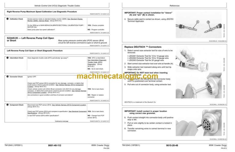
- 522449.05 — Left Reverse Pump Coil Open or Short
- Left Reverse Pump Coil Open or Short Diagnostic Procedure
- 522449.06 — Left Reverse Pump Coil Short to Power
- Left Reverse Pump Coil Short to Power Diagnostic Procedure
- 522449.15 — Left Reverse Pump Threshold Calibration High
- Left Reverse Pump Threshold Calibration High Diagnostic Procedur
- 522449.16 — Left Reverse Pump Maximum Speed Calibration Low
- Left Reverse Pump Maximum Speed Calibration Low Diagnostic Proce
- 522449.17 — Left Reverse Pump Threshold Calibration Low
- Left Reverse Pump Threshold Calibration Low Diagnostic Procedure
- 522449.18 — Left Reverse Pump Maximum Speed Calibration Too Low
- Left Reverse Pump Maximum Speed Calibration Too Low Diagnostic P
- 522450.05 — Left Forward Pump Coil Open or Short
- Left Forward Pump Coil Open or Short Diagnostic Procedure
- 522450.06 — Left Forward Pump Coil Short to Power
- Left Forward Pump Coil Short to Power Diagnostic Procedure
- 522450.15 — Left Forward Pump Threshold Calibration High
- Left Forward Pump Threshold Calibration High Diagnostic Procedur
- 522450.16 — Left Forward Pump Maximum Speed Calibration High
- Left Forward Pump Maximum Speed Calibration High Diagnostic Proc
- 522450.17 — Left Forward Pump Threshold Calibration Low
- Left Forward Pump Threshold Calibration Low Diagnostic Procedure
- 522450.18 — Left Forward Pump Maximum Speed Calibration Low
- Left Forward Pump Maximum Speed Calibration Low Diagnostic Proce
- 522451.05 — Cooler Bypass Solenoid No Response
- Cooler Bypass Solenoid No Response Diagnostic Procedure
- 522451.06 — Cooler Bypass Solenoid Short to Power
- Cooler Bypass Solenoid Short to Power Diagnostic Procedure
- 523108.13 — Pump/Motor Not Calibrated
- Pump/Motor Not Calibrated Diagnostic Procedure
- 523108.14 — VCU Not Calibrated
- VCU Not Calibrated Diagnostic Procedure
- 523577.05 — Left Motor Solenoid Open or Short
- Left Motor Solenoid Open or Short Diagnostic Procedure
- 523577.06 — Left Motor Solenoid Short to Power
- Left Motor Solenoid Short to Power Diagnostic Procedure
- 523577.13 — Motor High Speed Not Calibrated
- Motor High Speed Not Calibrated Diagnostic Procedure
- 523577.16 — Left Motor Maximum Calibration Too High
- Left Motor Maximum Calibration Too High Diagnostic Procedure
- 523577.18 — Left Motor Maximum Calibration Too Low
- Left Motor Maximum Calibration Too Low Diagnostic Procedure
- 523578.05 — Right Motor Solenoid Open or Short to Ground
- Right Motor Solenoid Open or Short to Ground Diagnostic Procedur
- 523578.06 — Right Motor Solenoid Short to Power
- Right Motor Solenoid Short to Power Diagnostic Procedure
- 523578.16 — Right Motor Maximum Calibration Too High
- Right Motor Maximum Calibration Too High Diagnostic Procedure
- 523578.18 — Right Motor Maximum Calibration Too Low
- Right Motor Maximum Calibration Too Low Diagnostic Procedure
- 524089.00 — Left System Pressure High
- 524089.01 — Left System Pressure Low
- 524089.03 — Left System Pressure Short to Power
- Left System Pressure Short to Power Diagnostic Procedure
- 524089.04 — Left System Pressure Open or Short
- Left System Pressure Open or Short Diagnostic Procedure
- 524090.00 — Right System Pressure High
- 524090.01 — Right System Pressure Low
- 524090.03 — Right System Pressure Short to Power
- Right System Pressure Short to Power Diagnostic Procedure
- 524090.04 — Right System Pressure Open or Short
- Right System Pressure Open or Short Diagnostic Procedure
- Blade Control Joystick (BCJ) Diagnostic Trouble Codes
- Diagnostic Trouble Code (DTC) Quick Reference List—Blade Control
- 002697.03 — Voltage Too High (X Axis)
- Voltage Too High (X Axis) Diagnostic Procedure
- 002697.04 — Voltage Too Low (X Axis)
- Voltage Too Low (X Axis) Diagnostic Procedure
- 002697.12 — Internal Failure (X Axis)
- Internal Failure (X Axis) Diagnostic Procedure
- 002697.13 — Input Not Calibrated (X Axis)
- Input Not Calibrated (X Axis) Diagnostic Procedure
- 002697.14 — Redundant Input Failure (X Axis)
- Redundant Input Failure (X Axis) Diagnostic Procedure
- 002698.03 — Voltage Too High (Y Axis)
- Voltage Too High (Y Axis) Diagnostic Procedure
- 002698.04 — Voltage Too Low (Y Axis)
- Voltage Too Low (Y Axis) Diagnostic Procedure
- 002698.12 — Internal Failure (Y Axis)
- Internal Failure (Y Axis) Diagnostic Procedure
- 002698.13 — Input Not Calibrated (Y Axis)
- Input Not Calibrated (Y Axis) Diagnostic Procedure
- 002698.14 — Redundant Input Failure (Y Axis)
- Redundant Input Failure (Y Axis) Diagnostic Procedure
- Electrohydraulic Controller (EHC) Diagnostic Trouble Codes
- Diagnostic Trouble Code (DTC) Quick Reference List—Electrohydrau
- 000158.03 — EHC System Volts Too High
- EHC System Volts Too High Diagnostic Procedure
- 000158.04 — EHC System Volts Too Low
- EHC System Volts Too Low Diagnostic Procedure
- 000620.03 — Sensor Short to Power
- Sensor Short to Power Diagnostic Procedure
- 000620.04 — Sensor Short to Ground
- Sensor Short to Ground Diagnostic Procedure
- 001903.00 — Auxiliary 1 PVE Open Circuit
- Auxiliary 1 PVE Open Circuit Diagnostic Procedure
- 001903.01 — Auxiliary 1 PVE Low or Open Circuit
- Auxiliary 1 PVE Low or Open Circuit Diagnostic Procedure
- 001903.03 — Auxiliary 1 PVE Short to Power
- Auxiliary 1 PVE Short to Power Diagnostic Procedure
- 001903.04 — Auxiliary 1 PVE Short to Ground
- Auxiliary 1 PVE Short to Ground Diagnostic Procedure
- 001903.31 — Auxiliary 1 PVE Spool Position Error
- Auxiliary 1 PVE Spool Position Error Diagnostic Procedure
- 001915.00 — Auxiliary 2 PVE Open Circuit
- Auxiliary 2 PVE Open Circuit Diagnostic Procedure
- 001915.01 — Auxiliary 2 PVE Low or Open Circuit
- Auxiliary 2 PVE Low or Open Circuit Diagnostic Procedure
- 001915.03 — Auxiliary 2 PVE Short to Power
- Auxiliary 2 PVE Short to Power Diagnostic Procedure
- 001915.04 — Auxiliary 2 PVE Short to Gound
- Auxiliary 2 PVE Short to Ground Diagnostic Procedure
- 001915.31 — Auxiliary 2 PVE Spool Position Error
- Auxiliary 2 PVE Spool Position Error Diagnostic Procedure
- 002000.09 — Missing ECU CAN Data
- Missing ECU CAN Data Diagnostic Procedure
- 002030.00 — Missing VCU CAN Data
- Missing VCU CAN Data Diagnostic Procedure
- 002660.09 — CAN Joystick Position Missing From BCJ
- CAN Joystick Position Missing From BCJ Diagnostic Procedure
- 003157.03 — Increment / Decrement Buttons Short to Power
- Increment / Decrement Buttons Short to Power Diagnostic Procedur
- 003157.04 — Increment / Decrement Buttons Open or Short
- Increment / Decrement Buttons Open or Short Diagnostic Procedure
- 003157.31 — Increment / Decrement Buttons Invalid Output
- Increment / Decrement Buttons Invalid Output Diagnostic Procedur
- 522442.03 — Blade Buttons Short to Power
- Blade Buttons Short to Power Diagnostic Procedure
- 522442.04 — Blade Buttons Open or Short
- Blade Buttons Open or Short Diagnostic Procedure
- 522422.31 — Blade Buttons Invalid Output
- Blade Buttons Invalid Output Diagnostic Procedure
- 523779.00 — Blade Rotate Current Above Maximum
- Blade Rotate Current Above Maximum Diagnostic Procedure
- 523779.01 — Blade Rotate Current Below Minimum
- Blade Rotate Current Below Minimum Diagnostic Procedure
- 523780.00 — Tilt PVE Open Circuit
- Tilt PVE Open Circuit Diagnostic Procedure
- 523780.01 — Tilt PVE Low or Open Circuit
- Tilt PVE Low or Open Circuit Diagnostic Procedure
- 523780.03 — Tilt PVE Short to Power
- Tilt PVE Short to Power Diagnostic Procedure
- 523780.04 — Tilt PVE Short to Ground
- Tilt PVE Short to Ground Diagnostic Procedure
- 523780.31 — Tilt PVE Spool Position Error
- Tilt PVE Spool Position Error Diagnostic Procedure
- 523781.00 — Height PVE Open Circuit
- Height PVE Open Circuit Diagnostic Procedure
- 523781.01 — Height PVE Low or Open Circuit
- Height PVE Low or Open Circuit Diagnostic Procedure
- 523781.03 — Height PVE Short to Power
- Height PVE Short to Power Diagnostic Procedure
- 523781.04 — Height PVE Short to Ground
- Height PVE Short to Ground Diagnostic Procedure
- 523781.31 — Height PVE Spool Position Error
- Height PVE Spool Position Error Diagnostic Procedure
- 524059.00 — Auxiliary 2 Joystick Sensor 2 Volts High
- Auxiliary 2 Joystick Sensor 2 Short Volts High Diagnostic Proced
- 524059.01 — Auxiliary 2 Joystick Sensor 2 Volts Low
- Auxiliary 2 Joystick Sensor 2 Short Volts Low Diagnostic Procedu
- 524059.03 — Auxiliary 2 Joystick Sensor 2 Short to Power
- Auxiliary 2 Joystick Sensor 2 Short to Power Diagnostic Procedur
- 524059.04 — Auxiliary 2 Joystick Sensor 2 Short to Ground
- Auxiliary 2 PVE Short to Power Diagnostic Procedure
- 524059.31 — Auxiliary 2 Joystick Sensor 2 Invalid Output
- Auxiliary 2 Joystick Sensor 2 Invalid Output Diagnostic Procedur
- 524062.00 — Auxiliary 1 Joystick Sensor 2 Volts High
- Auxiliary 1 Joystick Sensor 2 Volts High Diagnostic Procedure
- 524062.01 — Auxiliary 1 Joystick Sensor 2 Volts Low
- Auxiliary 1 Joystick Sensor 2 Volts Low Diagnostic Procedure
- 524062.03 — Auxiliary 1 Joystick Sensor 2 Short to Power
- Auxiliary 1 Joystick Sensor 2 Short to Power Diagnostic Procedur
- 524062.04 — Auxiliary 1 Joystick Sensor 2 Short to Ground
- Auxiliary 1 Joystick Sensor 2 Short to Ground Diagnostic Procedu
- 524062.31 — Auxiliary 1 Joystick Sensor 2 Invalid Output
- Auxiliary 1 Joystick Sensor 2 Invalid Output Diagnostic Procedur
- 524085.00 — Auxiliary 2 Joystick Sensor 1 Volts High
- Auxiliary 2 Joystick Sensor 1 Volts High Diagnostic Procedure
- 524085.01 — Auxiliary 2 Joystick Sensor 1 Volts Low
- Auxiliary 2 Joystick Sensor 1 Volts Low Diagnostic Procedure
- 524085.03 — Auxiliary 2 Joystick Sensor 1 Short to Power
- Auxiliary 2 Joystick Sensor 1 Short to Power Diagnostic Procedur
- 524085.04 — Auxiliary 2 Joystick Sensor 1 Short to Ground
- Auxiliary 2 Joystick Sensor 1 Short to Power Diagnostic Procedur
- 524085.14 — Auxiliary 2 Joystick Sensor Mismatch
- Auxiliary 2 Joystick Sensor Mismatch Diagnostic Procedure
- 524085.31 — Auxiliary 2 Joystick Sensor 1 Invalid Output
- Auxiliary 2 Joystick Sensor 1 Invalid Output Diagnostic Procedur
- 524086.00 — Auxiliary 1 Joystick Sensor 1 Volts High
- Auxiliary 1 Joystick Sensor 1 Volts High Diagnostic Procedure
- 524086.01 — Auxiliary 1 Joystick Sensor 1 Volts Low
- Auxiliary 1 Joystick Sensor 1 Volts Low Diagnostic Procedure
- 524086.03 — Auxiliary 1 Joystick Sensor 1 Short to Power
- Auxiliary 1 Joystick Sensor 1 Short to Power Diagnostic Procedur
- 524086.04 — Auxiliary 1 Joystick Sensor 1 Short to Ground
- Auxiliary 1 Joystick Sensor 1 Short to Ground Diagnostic Procedu
- 524086.14 — Auxiliary 1 Joystick Sensor Mismatch
- Auxiliary 1 Joystick Sensor Mismatch Diagnostic Procedure
- 524086.31 — Auxiliary 1 Joystick Sensor 1 Invalid Output
- Auxiliary 1 Joystick Sensor 1 Invalid Output Diagnostic Procedur
- Operational Checkout Procedure
- Operational Checkout Procedure
- Operational Checkout
- Diagnostic Trouble Code (DTC) Check
- Operational Checks—Ignition OFF, Engine OFF Checks
- Operational Checks—Ignition ON, Engine OFF
- Operational Checks—Ignition ON, Engine ON
- Engine
- Theory of Operation
- John Deere Engine
- Cold Start Aid System Theory of Operation—If Equipped
- Fast Fill Fuel System Theory of Operation—If Equipped
- Diagnostic Information
- John Deere Diesel Engine
- Engine Cooling System Component Location
- Engine Fuel System Component Location
- Engine Intake and Exhaust Component Location
- Fast Fill Fuel System Underfill—If Equipped
- Fast Fill Fuel System Underfill Diagnostic Procedure
- Fast Fill Fuel System Overfill—If Equipped
- Fast Fill Fuel System Overfill Diagnostic Procedure
- Fast Fill Fuel System Nozzle Leaks at Receiver—If Equipped
- Fast Fill Fuel System Nozzle Leaks at Receiver Diagnostic Proced
- Adjustments
- John Deere Engine
- Service Filter Cleaning
- Tests
- John Deere Engine
- Fuel Supply Pump Pressure Test
- Fluid Sampling Procedure—If Equipped
- Engine Idle Speeds and Auto Shutdown Check
- Exhaust Emissions Test Point
- Electrical System
- System Information
- Electrical Diagram Information
- Electrical Schematic Symbols
- System Diagrams
- Fuse and Relay Specifications
- System Functional Schematic, Component Location, and Wiring Diag
- System Functional Schematic
- JDLink™ Functional Schematic
- Engine Interface Harness (W10) Component Location
- Engine Interface Harness (W10) Wiring Diagram
- Cooling Package Harness (W11) Component Location
- Cooling Package Harness (W11) Wiring Diagram
- Fan Harness (W12) Component Location
- Fan Harness (W12) Wiring Diagram
- Vehicle Harness (W13) Component Location
- Vehicle Harness (W13) Wiring Diagram
- Vehicle (IGC Controls) Harness (W14) Component Location
- Vehicle (IGC Controls) Harness (W14) Wiring Diagram
- Engine Compartment Light Harness (W15) Component Location
- Engine Compartment Light Harness (W15) Wiring Diagram
- Fuel Tank Harness (W16) Component Location
- Fuel Tank Harness (W16) Wiring Diagram
- Operator’s Station Harness (W17) Component Location
- Operator’s Station Harness (W17) Wiring Diagram
- Operator’s Station (IGC Controls) Harness (W18) Component Locati
- Operator’s Station (IGC Controls) Harness (W18) Wiring Diagram
- Front Dash Harness (W19) Component Location
- Front Dash Harness (W19) Wiring Diagram
- Left Console Harness (W20) Component Location
- Left Console Harness (W20) Wiring Diagram
- Cab Roof Harness (W21) Component Location
- Cab Roof Harness (W21) Wiring Diagram
- Canopy Roof Harness (W22) Component Location
- Canopy Roof Harness (W22) Wiring Diagram
- Radio Harness (W23) Component Location
- Radio Harness (W23) Wiring Diagram
- Heater and Air Conditioner Harness (W24) Component Location
- Heater and Air Conditioner Harness (W24) Wiring Diagram
- Condenser Harness (W25) Component Location
- Condenser Harness (W25) Wiring Diagram
- Under Seat Heater Harness (W26) Component Location
- Under Seat Heater Harness (W26) Wiring Diagram
- Dome Light Harness (W28) Component Location
- Dome Light Harness (W28) Wiring Diagram
- Engine Harness (W29) Component Location
- Engine Harness (W29) Wiring Diagram
- Intake Air Sensor Harness (W30) Component Location
- Intake Air Sensor Harness (W30) Wiring Diagram
- Front Engine Harness (W31) Component Location
- Front Engine Harness (W31) Wiring Diagram
- Fuel Dosing Harness (W32) Component Location
- Fuel Dosing Harness (W32) Wiring Diagram
- Glow Plug Harness (W33) Component Location
- Glow Plug Harness (W33) Wiring Diagram
- Fuel Injector Harness (W34) Component Location
- Fuel Injector Harness (W34) Wiring Diagram
- JDLink™ System Harnesses (W6002 and W6003) Component Location
- Modular Telematics Gateway (MTG) Harness (W6002) Wiring Diagram
- Satellite (SAT) Harness (W6003) Wiring Diagram
- Sub-System Diagnostics
- Start and Charge Circuits Theory of Operation
- Park Brake Circuit Theory of Operation
- Controller Area Network (CAN) Theory of Operation
- Engine Control Unit (ECU) Circuit Theory of Operation
- Vehicle Control Unit (VCU) Circuit Theory of Operation
- Standard Display Monitor (SDM) Circuit Theory of Operation
- Integrated Grade Control (IGC) Circuit Theory of Operation—If Eq
- Exhaust Aftertreatment Circuit Theory of Operation
- Monitor Operation
- Standard Display Monitor (SDM)—Service Mode
- Standard Display Monitor (SDM)—Codes
- Standard Display Monitor (SDM)—Exhaust Filter
- Standard Display Monitor (SDM)—Service
- Standard Display Monitor (SDM)—Machine Settings
- Standard Display Monitor (SDM)—Diagnostics
- Standard Display Monitor (SDM)—Monitor
- Standard Display Monitor (SDM)—Calibrate
- Standard Display Monitor (SDM)—Vehicle Control Unit (VCU) Diagno
- Standard Display Monitor (SDM)—Software Delivery
- References
- Electrical Component Specifications
- Service ADVISOR™ Diagnostic Application
- Service ADVISOR™ Connection Procedure
- Reading Diagnostic Trouble Codes with Service ADVISOR™ Diagnosti
- Diagnostic Trouble Codes—After Machine Repair
- Integrated Grade Control (IGC) Checks—If Equipped
- Integrated Grade Control (IGC) Diagnose Malfunctions—If Equipped
- All Blade Functions Do Not Operate in Manual or Auto Modes
- All Blade Functions Operate Normally in Manual Mode, But Not in
- All Blade Functions Operate Normally in Auto Mode, But Not in Ma
- Blade Lift and Tilt Operate Normally in Auto Mode, But Not in Ma
- Blade Lift and Tilt Operate Normally, But Blade Angle Does Not
- Blade Lift and Angle Operate Normally, But Blade Incr/Decr Does
- Blade Response Is Not Smooth
- All Blade Functions Are Slow or Sluggish
- Blade Response Is Too Fast
- Blade Moves Quickly (Jumps) to One Side, Then Slowly Comes Back
- Waves in Graded Surface
- CAN Circuit Test
- Controller Area Network (CAN) Diagnostics
- Alternator Test Procedure
- Vehicle Control Unit (VCU) Calibration
- Wire Harness Test
- Decelerator/Brake Pedal Adjustment
- Engine Speed Control Remove and Install
- Exhaust Filter Sensor Installation
- Rotary Sensor Remove and Install
- Transmission Control Lever (TCL) Adjustment
- Controller Remove and Install
- Intermittent Diagnostic Trouble Code (DTC) Diagnostics
- Replace WEATHER PACK WEATHER PACK is a trademark of Packard Elec
- Install WEATHER PACK WEATHER PACK is a trademark of Packard Elec
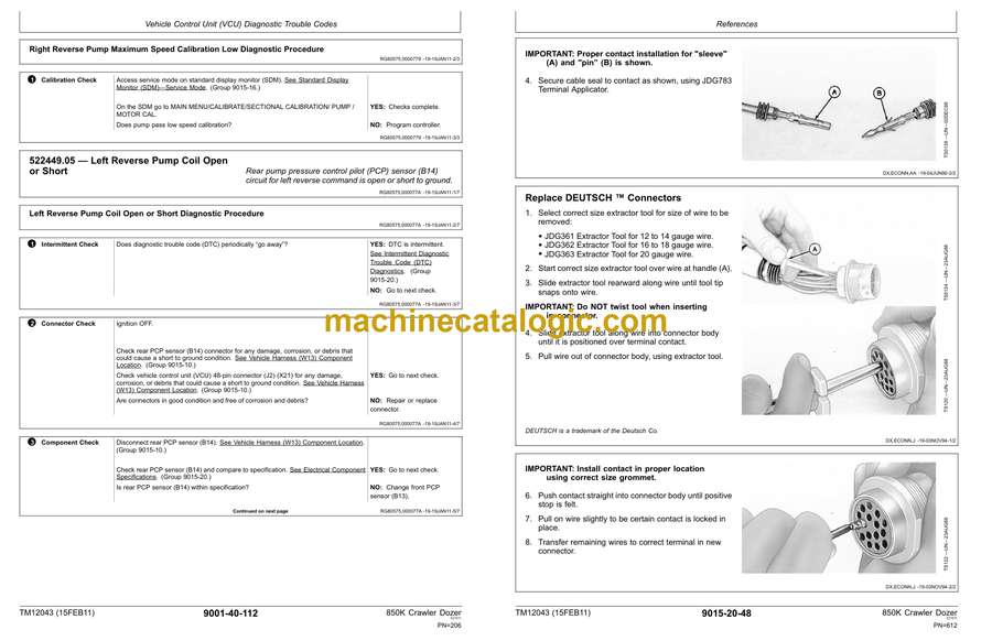
- Replace DEUTSCH DEUTSCH is a trademark of the Deutsch Co.™ Conne
- Replace DEUTSCHDEUTSCH is a trademark of Deutsch Co.™ Rectangula
- Install DEUTSCH DEUTSCH is a trademark of the Deutsch Co.™ Conta
- Replace CINCHCINCH is a trademark of the Cinch Co.™ Connectors
- Install CINCHCINCH is a trademark of the Cinch Co.™ Contact
- Repair 32 and 48 Way CINCHCINCH is a trademark of the Cinch Co.™
- Replace (Pull Type) Metri-Pack™ Connectors
- Replace (Push Type) Metri-Pack™ Connectors
- Hydraulics
- Theory
- Hydraulic System Operation
- Hydraulic Pump Operation
- Hydraulic Control Valve Operation
- Hydraulic Control Valve Operation—IGC
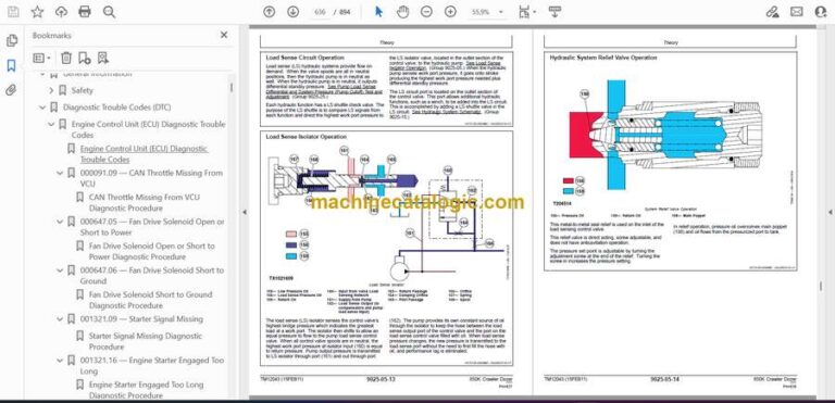
- Load Sense Circuit Operation
- Load Sense Isolator Operation
- Hydraulic System Relief Valve Operation
- Circuit Relief Valve with Anticavitation Operation
- Hydraulic Oil Filter Manifold Operation
- Blade Angle Operation
- Ripper Operation
- Ripper Operation with IGC Controlled Auxiliary Valve
- Quick-Drop Valve Operation
- Hydraulic Reversing Fan Drive Operation
- Diagnostic Information
- Hydraulic System Schematic
- Hydraulic System Schematic—IGC
- Hydraulic System Schematic—IGC with Auxiliary Valve
- Main Hydraulic Component Location
- Main Hydraulic Component Location—IGC
- Ripper Ready Hydraulic Component Location
- Ripper Ready Hydraulic Component Location—IGC
- Winch Ready Hydraulic Component Location
- Hydraulic System Diagnose Malfunctions
- No Hydraulic Functions Diagnostic Procedure
- Hydraulic Functions Slow Diagnostic Procedure
- Hydraulic Pump Noisy Diagnostic Procedure
- Blade Float Does Not Work Diagnostic Procedure
- One Hydraulic Function Does Not Work Diagnostic Procedure
- Function Drifts Down Diagnostic Procedure
- Oil Overheats Diagnostic Procedure
- Hydraulic System Diagnose Malfunctions—IGC
- No Hydraulic Functions Diagnostic Procedure—IGC
- Hydraulic Functions Slow Diagnostic Procedure—IGC
- Blade Float Does Not Work Diagnostic Procedure—IGC
- One Hydraulic Function Does Not Work Diagnostic Procedure—IGC
- Hydraulic Power Low Diagnostic Procedure—IGC
- Function Drifts Down Diagnostic Procedure—IGC
- Oil Overheats Diagnostic Procedure—IGC
- Blade Response Not Smooth Diagnostic Procedure—IGC
- Hydraulic Fan Does Not Reach Full Speed
- Hydraulic Fan Does Not Reach Full Speed Diagnostic Procedure
- Hydraulic Fan Runs at Full Speed Only
- Hydraulic Fan Runs at Full Speed Only Diagnostic Procedure
- Hydraulic Fan Does Not Spin
- Hydraulic Fan Does Not Spin Diagnostic Procedure
- Hydraulic Fan Will Not Reverse Direction
- Hydraulic Fan Will Not Reverse Direction Diagnostic Procedure
- Tests
- JT02156A Digital Pressure and Temperature Analyzer Kit Installat
- JDG1770 Ultra Clean Hand Launcher
- Hydraulic Oil Cleanup Procedure
- Blade Down Accumulator Hydraulic Discharge
- Blade Down Accumulator Precharge Test
- Pump Load Sense Differential and System Pressure (Load Sense Rel
- Pump Load Sense Differential and System Pressure (Load Sense Rel
- Hydraulic System Relief Valve Test
- Hydraulic System Relief Valve Test—IGC
- Circuit Relief Valve Test
- Circuit Relief Valve Test—IGC
- Lift and Tilt Cylinder Function Drift Test
- Cylinder Leakage Test
- Pressure Reducing Valve Pressure Test and Adjustment
- Hydraulic Pump Flow Test
- Hydraulic Pump Case Drain Test
- Fan Pump Flow Test
- Fan Motor Speed Test
- Fan Motor Case Drain Test
- Hydrostatic System
- Theory of Operation
- Hydrostatic System Operation
- Transmission Control Circuit Operation (Flow Chart)
- Charge Pump Operation
- Hydrostatic Charge Oil Filter Operation
- Neutral Charge Relief Valve Operation
- Multi-Function Valve Operation
- Hydraulic Integrated Circuit (HIC) Valve Operation
- Park Brake Valve Operation
- Oil Cooler and Reservoir Bypass Operation
- Pump Pressure Control Pilot (PCP) Operation
- Pump Displacement Control Valve (PDCV) Operation
- Hydrostatic Pump Operation
- Flushing Valve and Operating Charge Relief Valve Operation
- Hydrostatic Motor Operation
- Hydrostatic Cold Start Valve Operation
- Diagnostic Information
- Hydrostatic System Schematic—Neutral (Park Brake On)
- Hydrostatic System Component Location
- Hydrostatic System Line Identification
- Park Brake System Component Location
- Hydrostatic System Diagram—Neutral (Park Brake On)
- Hydrostatic System Diagram—Reverse (Slow Speed)
- Hydrostatic System Diagram—Forward (Fast Speed)
- Overheating Malfunctions
- Overheating Diagnostic Procedure
- Low Charge Pressure Malfunctions
- Low Charge Pressure Diagnostic Procedure
- Mistrack/Index Malfunctions
- Machine Full Speed Malfunctions
- Machine Will Not Reach Full Speed Diagnostic Procedure
- Low Power Malfunctions
- Low Power Diagnostic Procedure
- Track Malfunctions
- Engine Starts But One Or Both Tracks Will Not Move Diagnostic Pr
- VCU Calibration Malfunctions
- VCU Calibration Malfunctions Diagnostic Procedure
- Tests
- JT02156A Digital Pressure and Temperature Analyzer Kit Installat
- JDG1770 Ultra Clean Hand Launcher
- Machine Supporting Procedure
- Transmission Oil Warm-Up Procedure
- Releasing Park Brake to Tow the Machine
- Hydrostatic Pump and Motor Initial Start-Up Procedure
- Hydrostatic Pump Flushing Procedure
- Hydraulic Oil Cleanup Procedure
- Pressure Control Pilot (PCP) Manual Override Test
- Pressure Control Pilot (PCP) Test
- Pressure Control Pilot (PCP) Internal Adjustment
- Multi-Function Relief Valve Test
- Transmission Efficiency Test
- Neutral Charge Relief and Operating Charge Relief Pressure Test
- Pump Displacement Control Valve (PDCV) Neutral (Null) Adjustment
- Pump Servo Pressure Test
- Motor Displacement Control Valve (MDCV) Adjustment
- Hydrostatic Motor Min./Max. Angle Servo Piston Pressure Test
- Charge Pump Flow Test
- Charge Pressure Sensor Test
- Hydrostatic Cold Start Valve Test
- Hydrostatic Oil Cooler Bypass Test
- Hydrostatic Oil Reservoir Bypass Test
- Park Brake Test
- Park Brake Relief Valve Test
- Cab Tilt Relief Valve Test
- Hand Pump Bleed Procedure
- Heating and Air Conditioning
- Theory of Operation
- Air Conditioning System Cycle Of Operation
- Diagnostic Information
- Heater and Air Conditioner System Component Location
- Diagnose Air Conditioning System Malfunctions
- Air Conditioner System Does Not Operate
- Air Conditioner System Does Not Operate Diagnostic Procedure
- Air Conditioner Does Not Cool Interior of Cab
- Air Conditioner Does Not Cool Interior of Cab Diagnostic Procedu
- Air Conditioner Runs Constantly, Too Cool
- Air Conditioner Runs Constantly, Too Cold Diagnostic Procedure
- Diagnose Heater System Malfunctions
- Heater System Does Not Operate
- Heater System Does Not Operate Diagnostic Procedure
- Heater Does Not Warm Interior of Cab
- Heater Does Not Warm Interior of Cab Diagnostic Procedure
- Interior Windows Continue to Fog
- Interior Windows Continue to Fog Diagnostic Procedure
- Tests
- Refrigerant Cautions and Proper Handling
- R134a Refrigerant Cautions
- Air Conditioner and Heater Operational Checks
- Visual Inspection Of Components
- R134a Oil Charge Capacity
- R134a Refrigerant Charge Capacity
- Refrigerant Hoses And Tubing Inspection
- Refrigerant Leak Test
- Air Conditioner Compressor Clutch Test
- Air Conditioner High/Low Pressure Switch Test
- Air Conditioner Freeze Control Switch Test
- R134a Air Conditioning System Test
- Operating Pressure Diagnostic Chart
- Page Number
- Section 9000
- Section 9001
- Group 10
- Group 20
- Group 30
- Group 40
- Group 50
- Group 60
- Section 9005
- Section 9010
- Group 05
- Group 15
- Group 20
- Group 25
- Section 9015
- Group 05
- Group 10
- Group 15
- Group 16
- Group 20
- Section 9025
- Group 05
- Group 15
- Group 25
- Section 9026
- Group 05
- Group 15
- Group 25
- Section 9031
- Group 05
- Group 15
- Group 25
John Deere
