Format: PDF (Printable Document)
File Language: English
File Pages: 475
File Size: 5.01 MB (Speed Download Link)
Brand: John Deere
Model: Excavator 230LCR Maintenance Repair Parts Lists
Book No: TM 5-3805-280-24-1
Type of Document: Technical Manual
$ 40
General Information
01 Safety……………………………………………………………………………………………….1-1
Follow Safe Procedures………………………………………………………………….1-1
Prepare for Emergencies ………………………………………………………………..1-1
Handle Fluids Safely—Avoid Fires …………………………………………………1-1
Prevent Battery Explosions …………………………………………………………….1-2
Handle Chemical Products Safely……………………………………………………1-2
Prevent Acid Burns ……………………………………………………………………….1-3
Avoid High-Pressure Fluids ……………………………………………………………1-4
Warn Others of Service Work …………………………………………………………1-4
Park Machine Safely ……………………………………………………………………..1-5
Support Machine Properly………………………………………………………………1-5
Operate Only From Operator’s Seat…………………………………………………1-5
TM 5-3805-280-24-1
TABLE OF CONTENTS (Continued)
Page
ii
Stay Clear of Moving Parts …………………………………………………………….1-6
Avoid Power Lines………………………………………………………………………..1-6
Use Handholds and Steps ……………………………………………………………….1-6
Keep Riders Off Machine……………………………………………………………….1-7
Move and Operate Machine Safely ………………………………………………….1-7
Wear Protective Clothing ……………………………………………………………….1-7
Protect Against Flying Debris …………………………………………………………1-8
Protect Against Noise…………………………………………………………………….1-8
Illuminate Work Area Safely…………………………………………………………..1-8
Service Machines Safely ………………………………………………………………..1-8
Remove Paint Before Welding or Heating………………………………………..1-9
Avoid Heating Near Pressurized Fluid Lines …………………………………….1-9
Beware of Exhaust Fumes………………………………………………………………1-10
Use Proper Lifting Equipment…………………………………………………………1-10
Service Cooling System Safely ……………………………………………………….1-10
Dispose of Waste Properly……………………………………………………………..1-11
Work in a Clean Area…………………………………………………………………….1-11
Use Tools Properly………………………………………………………………………..1-12
Replace Safety Signs ……………………………………………………………………..1-12
Live With Safety …………………………………………………………………………..1-12
Battery Terminals, Lifting Equipment, Dry Cleaning, Solvent
and Compressed Air ……………………………………………………………………1-13
Compressor Equipment Hazards ……………………………………………………..1-14
Rock Drill Precautions …………………………………………………………………..1-16
02 General Specifications ………………………………………………………………………..1-19
03 Torque Values……………………………………………………………………………………1-20
Unified Inch Bolt and Cap Screw Torque Values ………………………………1-20
Metric Bolt and Cap Screw Torque Values……………………………………….1-21
Additional Metric Cap Screw Torque Values ……………………………………1-22
Check Oil Lines and Fittings…………………………………………………………..1-23
Service Recommendations for O-Ring Boss Fittings………………………….1-24
Service Recommendations for Flat Face O-Ring Seal Fittings …………….1-26
Service Recommendations for 37° Flare and
30° Cone Seat Connectors …………………………………………………………..1-27
Service Recommendations for Flared Connections—
Straight or Tapered Threads ………………………………………………………..1-28
Service Recommendations for Inch Series Four Bolt Flange Fittings……1-29
Service Recommendations for Metric Series Four Bolt Flange Fitting….1-31
04 Fuels and Lubricants…………………………………………………………………………..1-32
Diesel Fuel …………………………………………………………………………………..1-32
Lubricity of Diesel Fuels………………………………………………………………..1-32
Low Sulfur Diesel Fuel Conditioner ………………………………………………..1-33
Diesel Fuel Storage ……………………………………………………………………….1-33
Fuel Tank …………………………………………………………………………………….1-34
Do Not Use Galvanized Containers …………………………………………………1-34
Diesel Engine and Pump Gearbox Oils …………………………………………….1-35
Hydraulic Oil………………………………………………………………………………..1-36
Swing Gearbox and Propel Gearbox Oils………………………………………….1-37
Track Roller, Front Idler, and Carrier Roller Oil ……………………………….1-37
Track Adjuster, Working Tool Pivot, Swing Bearing, and
Swing Bearing Gear Grease…………………………………………………………1-38
Oil Filters …………………………………………………………………………………….1-38
Rock Drill Lubricants Specifications ……………………………………………….1-39
Lubricant Storage ………………………………………………………………………….1-41
Alternative and Synthetic Lubricants ……………………………………………….1-41
Mixing of Lubricants……………………………………………………………………..1-42
Air Compressor Lubrication……………………………………………………………1-43
Chapter 2 Section 9005 Operational Checkout Procedure
10 Operational Checkout Procedure………………………………………………………….2-1
Operational Checkout…………………………………………………………………….2-1
Operator Station Checks—Key Switch On, Engine Off ……………………..2-2
Operator Station Checks—Engine On………………………………………………2-5
Hydraulic System Checks ………………………………………………………………2-11
Undercarriage Checks ……………………………………………………………………2-19
Accessories Checks ……………………………………………………………………….2-21
Seat, Doors, Windows, Latches, and Locks Checks……………………………2-23
Engine Cooling System Checks ………………………………………………………2-29
Air Intake System Checks ………………………………………………………………2-33
Fuel System Checks ………………………………………………………………………2-36
Visual Inspection…………………………………………………………………………..2-38
Chapter 3 Section 9010 Engine
05 Theory of Operation …………………………………………………………………………..3-1
Engine—Sectional View………………………………………………………………..3-1
Fan Drive……………………………………………………………………………………..3-2
Engine Speed Control
System Operation……………………………………………………………………….3-3
Engine RPM Dial……………………………………………………………………….3-5
E (Economy) Mode…………………………………………………………………….3-7
HP (High Power) Mode ………………………………………………………………3-8
Auto-Idle Mode …………………………………………………………………………3-10
Engine Speed Learning……………………………………………………………….3-11
10 System Operational Checks…………………………………………………………………3-13
Engine Operational Checks …………………………………………………………….3-13
Cooling System Checks………………………………………………………………….3-13
Air Intake System Checks ………………………………………………………………3-18
Lubrication System Checks…………………………………………………………….3-21
Fuel System Checks ………………………………………………………………………3-23
Engine Speed and Performance Checks ……………………………………………3-25
15 Diagnostic Information……………………………………………………………………….3-28
Diagnose Engine Malfunctions ……………………………………………………….3-28
20 Adjustments ………………………………………………………………………………………3-40
JT05801 Clamp-On Electronic Tachometer Installation……………………..3-40
Fuel Shut-Off Solenoid Linkage, Check and Adjust …………………………..3-41
Engine Speed Check………………………………………………………………………3-44
Injection Pump Fast and Slow Idle Stops………………………………………….3-45
Engine Control Motor and Sensor……………………………………………………3-48
Engine Speed Learning Procedure …………………………………………………..3-49
Cooling System Fill and Deaeration…………………………………………………3-51
25 Tests…………………………………………………………………………………………………3-52
Fuel Line Leakage…………………………………………………………………………3-52
Air Filter Restriction Indicator Switch ……………………………………………..3-53
Air Intake System Leakage …………………………………………………………….3-54
Radiator Air Flow………………………………………………………………………….3-55
Engine Power Test Using Turbocharger Boost Pressure……………………..3-58
Torsional Dampener, Inspect ………………………………………………………….3-62
TM 5-3805-280-24-1
TABLE OF CONTENTS (Continued)
Page
iv
Chapter 4 Section 9015 Electrical System
05 System Information ……………………………………………………………………………4-1
Visually Inspect Electrical System…………………………………………………..4-1
Circuit Malfunctions
Circuit Malfunctions…………………………………………………………………..4-2
Definition………………………………………………………………………………….4-3
Location ……………………………………………………………………………………4-8
Troubleshooting…………………………………………………………………………4-9
Circuit Shorted to Power and Circuit Shorted to Itself………………………..4-11
Using Test Equipment
Multimeter ………………………………………………………………………………..4-14
Seven Step Electrical Test Procedure ……………………………………………4-15
System Functional Schematic Information………………………………………..4-16
Reading a System Functional Schematic Diagram……………………………..4-17
Reading a Harness Component Location Diagram …………………………….4-19
Electrical Schematic Symbols …………………………………………………………4-23
10 System Diagrams……………………………………………………………………………….4-26
Fuse Specifications………………………………………………………………………..4-26
Fuse (Blade-Type) Color Codes………………………………………………………4-27
Component Identification Table………………………………………………………4-27
Functional Schematic and Component Location Legend…………………….4-29
System Functional Schematic Section Legend…………………………………..4-33
System Functional Schematic (SE1—SE3)……………………………………….4-34
System Functional Schematic (SE4—SE6)……………………………………….4-35
System Functional Schematic (SE7—SE9)……………………………………….4-36
System Functional Schematic (SE10—SE12)……………………………………4-37
System Functional Schematic (SE13—SE15)……………………………………4-38
System Functional Schematic (SE16—SE18)……………………………………4-39
System Functional Schematic (SE19) ………………………………………………4-40
Engine and Frame Harness (W1)
Component Location ………………………………………………………………….4-41
Connectors, Wire and Pin Location ………………………………………………4-45
Air Compressor and Rock Drill Harness (W10) Component Location….4-49
Cab Harness (W2)
Component Location ………………………………………………………………….4-50
Component Location—Detail A (Harness Mating Connectors) ………..4-51
Component Location—Detail B (Fuse Block)………………………………..4-53
Connectors, Wire and Pin Location ………………………………………………4-54
Monitor and Relay Harness (W3)
Component Location ………………………………………………………………….4-60
Component Location—Detail A (Monitor Controller Connectors) ……4-61
Component Location—Detail B (Monitor Controller Indicators) ……..4-62
Connectors, Wire and Pin Location ………………………………………………4-63
Air Conditioner Harness (W9)
Component Location—See Group 9031-15 …………………………………..4-65
Connectors, Wire and Pin Location—See Group 9031-15……………….4-65
15 Sub-System Diagnostics ……………………………………………………………………..4-66
Power Circuit
Operational Information ……………………………………………………………..4-66
Theory of Operation …………………………………………………………………..4-67
Schematic………………………………………………………………………………….4-68
Power Circuit Diagnostic Procedures……………………………………………….4-69
Charging Circuit
Operational Information ……………………………………………………………..4-73
Theory of Operation …………………………………………………………………..4-73
Schematic………………………………………………………………………………….4-74
Alternator Theory of Operation……………………………………………………….4-75
Charging Circuit Diagnostic Procedures …………………………………………..4-76
Starting and Fuel Shutoff Circuit
Operational Information ……………………………………………………………..4-80
Theory of Operation …………………………………………………………………..4-80
Schematic………………………………………………………………………………….4-81
Starting Circuit Diagnostic Procedures …………………………………………….4-82
Windshield Wiper and Washer Circuit
Operational Information ……………………………………………………………..4-88
Theory of Operation …………………………………………………………………..4-89
Schematic………………………………………………………………………………….4-91
Windshield Wiper and Washer Circuit Diagnostic Procedures…………….4-92
Work and Drive Light Circuit
Operational Information ……………………………………………………………..4-97
Theory of Operation …………………………………………………………………..4-97
Schematic………………………………………………………………………………….4-98
Work and Drive Light Circuit Diagnostic Procedures ………………………..4-99
Accessory Circuits
Operational Information ……………………………………………………………..4-102
Theory of Operation …………………………………………………………………..4-102
Schematic………………………………………………………………………………….4-103
Accessory Circuits Diagnostic Procedures………………………………………..4-104
Quick Hitch Circuit
Operational Information ……………………………………………………………..4-106
Theory of Operation …………………………………………………………………..4-106
Schematic………………………………………………………………………………….4-107
Quick Hitch Circuit Diagnostic Procedures ………………………………………4-107
Heater Circuit (Machines Without Air Conditioner)…………………………..4-108
Heater Circuit (Machines With Air Conditioner)……………………………….4-109
Monitor Controller and Display Circuit
Specifications…………………………………………………………………………….4-110
Operational Information ……………………………………………………………..4-111
Theory of Operation …………………………………………………………………..4-112
Schematic………………………………………………………………………………….4-115
Monitor Controller and Display Circuit Diagnostic Procedures …………..4-116
Engine and Pump Controller Circuit
Operational Information ……………………………………………………………..4-133
Theory of Operation …………………………………………………………………..4-134
Schematic………………………………………………………………………………….4-136
Engine and Pump Controller Circuit Diagnostic Procedures ……………….4-137
Travel Alarm Circuit
Operational Information ……………………………………………………………..4-160
Theory of Operation …………………………………………………………………..4-160
Schematic………………………………………………………………………………….4-161
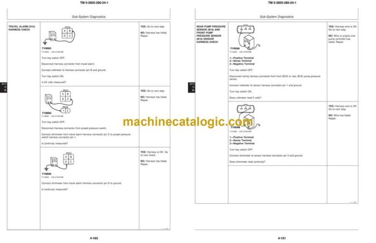
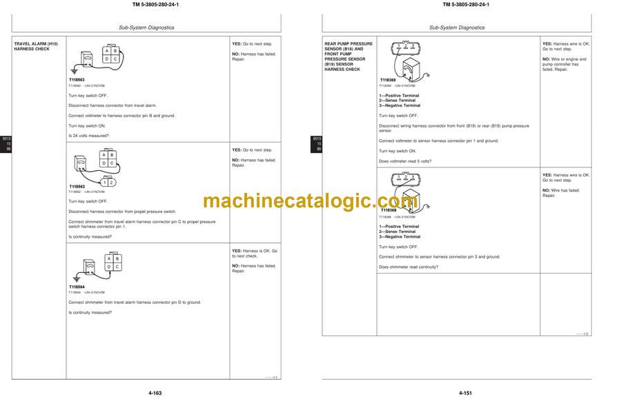
Travel Alarm Circuit Diagnostic Procedures …………………………………….4-162
Overload Alarm Circuit
Operational Information ……………………………………………………………..4-165
Theory of Operation …………………………………………………………………..4-165
Schematic………………………………………………………………………………….4-166
Overload Alarm Circuit Diagnostic Procedures…………………………………4-166
20 References ………………………………………………………………………………………..4-169
Battery
Operation ………………………………………………………………………………….4-169
Specifications…………………………………………………………………………….4-170
TM 5-3805-280-24-1
TABLE OF CONTENTS (Continued)
Page
vi
Diagnose Malfunctions ……………………………………………………………….4-171
Check Electrolyte Level and Terminals…………………………………………4-172
Batteries
Procedure for Testing …………………………………………………………………4-174
Using Booster Batteries—24 Volt System……………………………………..4-175
Replacing ………………………………………………………………………………….4-176
Adding 12 or 24 Volt Accessories ………………………………………………..4-177
Travel Alarm, Changing Volume …………………………………………………….4-178
Test Harness
Proportional Solenoid …………………………………………………………………4-179
Pump Control…………………………………………………………………………….4-179
Pump Pressure Sensor…………………………………………………………………4-179
Chapter 5 Section 9020 Power Train
05 Theory of Operation …………………………………………………………………………..5-1
Track Adjuster………………………………………………………………………………5-1
Propel Gearbox……………………………………………………………………………..5-2
15 Diagnostic Information……………………………………………………………………….5-4
Diagnose Undercarriage Components Malfunctions…………………………..5-4
Track Chain
Measure Bushing Wear……………………………………………………………….5-6
Measure Link Wear ……………………………………………………………………5-7
Measure Pitch ……………………………………………………………………………5-8
Track Shoe Grouser
Measure Wear (SN —599999) …………………………………………………….5-9
Measure Wear (SN 600000—) …………………………………………………….5-10
Track Roller, Measure Wear …………………………………………………………..5-11
Track Carrier Roller, Measure Wear………………………………………………..5-12
Front Idler, Measure Wear ……………………………………………………………..5-13
Swing Bearing, Measure Wear………………………………………………………..5-14
20 Adjustments ………………………………………………………………………………………5-16
Track Sag …………………………………………………………………………………….5-16
Chapter 6 Section 9025 Hydraulic System
05 Theory of Operation …………………………………………………………………………..6-1
Hydraulic System Diagram…………………………………………………………….6-1
Pilot Pump Operation …………………………………………………………………….6-2
Pilot Pressure Regulating Valve and Filter Operation…………………………6-3
Pilot Shut-Off Valve Operation……………………………………………………….6-4
Pilot Controller
Neutral ……………………………………………………………………………………..6-6
Metering and Full Stroke …………………………………………………………….6-7
Propel Pilot Controller …………………………………………………………………..6-8
Pilot Controller Operation of Control Valve ……………………………………..6-10
Flow Regulator Valve ……………………………………………………………………6-11
Hydraulic Pump and Drive Gearbox ………………………………………………..6-13
Hydraulic Pump Operation……………………………………………………………..6-15
Hydraulic Pump Regulator
Component Operation…………………………………………………………………6-17
Operation ………………………………………………………………………………….6-19
Increasing, Maximum, and Decreasing …………………………………………6-21
Summation and Speed Sensing…………………………………………………….6-23
Proportional Solenoid Valve
Manifold Operation ……………………………………………………………………6-25
Arm Regenerative, Speed Sense, Propel Speed Change,
and Power Boost …………………………………………………………………….6-27
Engine Speed Sensing Control Circuit ……………………………………………..6-29
Control Valve
Component Identification Operation …………………………………………….6-30
Circuit Schematic……………………………………………………………………….6-34
Pilot Pressure Signal Passage ………………………………………………………6-36
Neutral and Power Passages ………………………………………………………..6-38
System Relief and Power Boost Valve……………………………………………..6-40
Power Boost Control Circuit …………………………………………………………..6-41
Circuit Relief Valve ………………………………………………………………………6-42
Pump Control Valve………………………………………………………………………6-43
Flow Combiner Valve ……………………………………………………………………6-45
Arm Regenerative Valve ………………………………………………………………..6-47
Boom and Arm Reduced Leakage Valves…………………………………………6-49
Bucket Flow Control Valve…………………………………………………………….6-50
Propel Flow Control Valve……………………………………………………………..6-52
Propel-Boom Down Selector Valve …………………………………………………6-53
Boom Regenerative Valve………………………………………………………………6-54
Propel and Arm In Combined …………………………………………………………6-55
Swing and Boom Up Combined………………………………………………………6-57
Swing Gearbox……………………………………………………………………………..6-59
Swing Motor
Operation ………………………………………………………………………………….6-61
Crossover Relief Valve……………………………………………………………….6-63
Make-Up Valve …………………………………………………………………………6-64
Park Brake Release Valve……………………………………………………………6-65
Rotary Manifold ……………………………………………………………………………6-67
Propel Motor
Operation ………………………………………………………………………………….6-68
Slow Speed ……………………………………………………………………………….6-70
Fast Speed…………………………………………………………………………………6-71
Speed Change Circuit …………………………………………………………………6-72
Park Brake Valve Housing ………………………………………………………….6-74
Park Brake Release Circuit ………………………………………………………….6-76
Counterbalance Valve…………………………………………………………………6-78
Cylinder Boom, Arm, and Bucket……………………………………………………6-80
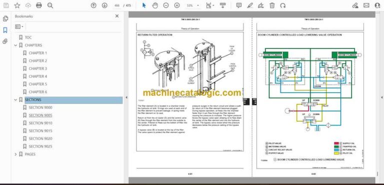
Return Filter …………………………………………………………………………………6-81
Boom Cylinder Controlled Load Lowering Valve Operation ………………6-82
Auxiliary Hydraulics Operation ………………………………………………………6-84
Hydraulic System Circuit Symbols ………………………………………………….6-86
Schematic
Pilot Controllers Circuit………………………………………………………………6-87
Hydraulic Pump and Control Valve………………………………………………6-88
Swing and Propel Motor……………………………………………………………..6-89
15 Diagnostic Information……………………………………………………………………….6-90
Diagnostic Procedure …………………………………………………………………….6-90
Diagnose Malfunctions
Electronic and Control Valve Component ……………………………………..6-91
Hydraulic System……………………………………………………………………….6-101
Pilot Circuit……………………………………………………………………………….6-104
Dig Circuit ………………………………………………………………………………..6-106
Swing Circuit …………………………………………………………………………….6-108
Propel System……………………………………………………………………………6-110
Control Lever Pattern Conversion……………………………………………………6-113
TM 5-3805-280-24-1
TABLE OF CONTENTS (Continued)
Page
viii
Control Valve Line Identification
Left Front ………………………………………………………………………………….6-114
Right Rear…………………………………………………………………………………6-116
Bottom ……………………………………………………………………………………..6-118
Control Valve Component Identification
Left Front ………………………………………………………………………………….6-119
Right Rear…………………………………………………………………………………6-121
Bottom ……………………………………………………………………………………..6-123
Component Location
Main Hydraulic System………………………………………………………………6-124
Pilot Controllers-to-Flow Regulator—SAE Pattern…………………………6-125
Pilot Controllers-to-Flow Regulator—John Deere Pattern ……………….6-126
Pilot Flow Regulator-to-Control Valve …………………………………………6-127
Propel System……………………………………………………………………………6-128
Pressure and Return System ………………………………………………………..6-129
20 Adjustment ……………………………………………………………………………………….6-130
Pilot Shut-Off Valve Linkage………………………………………………………….6-130
25 Tests…………………………………………………………………………………………………6-131
Laptop Computer General Description……………………………………………..6-131
Excavator Diagnostics Program
Overview ………………………………………………………………………………….6-131
Install ……………………………………………………………………………………….6-132
Uninstall……………………………………………………………………………………6-137
Starting……………………………………………………………………………………..6-137
Feature—Service Codes ……………………………………………………………..6-141
Feature—Monitor Data……………………………………………………………….6-143
Feature—Saving Monitor Data…………………………………………………….6-145
Special Function—Engine Speed Adjustment ………………………………..6-146
Service Codes List ……………………………………………………………………..6-150
Monitor Data Items…………………………………………………………………….6-151
Special Function—Engine Speed Factory Settings Parameters…………6-152
Engine Speed to Pump Flow Rate Chart …………………………………………..6-153
Excavator Diagnostics Program Troubleshooting………………………………6-155
Reading Service Codes Without Excavator Diagnostics Program ………..6-156
Engine and Pump Controller Functions ……………………………………………6-158
JT05801Clamp-On Electronic Tachometer Installation………………………6-159
JT05800 Digital Thermometer Installation ……………………………………….6-160
JT02156A Digital Pressure and Temperature Analyzer Installation ……..6-160
Start-Up Procedure
Hydraulic Pump…………………………………………………………………………6-161
Swing Motor ……………………………………………………………………………..6-162
Swing Gearbox ………………………………………………………………………….6-163
Propel Motor……………………………………………………………………………..6-164
Hydraulic Oil Filter Inspection Procedure ………………………………………..6-164
Hydraulic Oil Cleanup Procedure Using Portable Filter Caddy……………6-165
Hydraulic System Warm-Up Procedure……………………………………………6-166
Lower Boom With Engine Stopped (Using Boom Cylinder
Load Lowering Valve)………………………………………………………………..6-167
Lower Boom With Engine Stopped (When Not Equipped With
Boom Cylinder Load Lowering Valve) …………………………………………6-169
Harness Test
Arm Regenerative Proportional Solenoid Valve (SC) ……………………..6-171
Speed Sensing Solenoid Valve (SD)……………………………………………..6-173
Propel Speed Change Proportional Solenoid Valve (SI) ………………….6-175
Power Boost Proportional Solenoid Valve (SG)……………………………..6-177
and more
