Format: PDF (Printable Document)
File Language: English
File Pages: 37
File Size: 0.71 MB (Speed Download Link)
Brand: Kohler
Model: 340 KN-Series Nonautomatic Transfer Switches
Book No: tp5585
Type of Document: Operation and Installation Manual
$ 40
In a facility or commercial building where you’ve got a standby generator feeding a Kohler 340 KN-Series nonautomatic transfer switch, this manual is what you use to make sure power is shifted safely and correctly when the utility fails. It walks you through how to operate and install the switch so you don’t damage equipment or leave the building dark. For example, if the switch refuses to transfer back to utility after the generator is running steady, this manual helps you trace the problem—whether it’s in the wiring, the mechanical interlock, or an incorrect operating sequence.
Applications & Use Cases
FAQ
Q: Can I keep a digital copy of this manual on my phone or tablet for field work?
A: Yes, it’s practical to use a digital copy on-site, but make sure it’s readable offline in case you lose connectivity.
Q: Is it worth printing this manual for the electrical room?
A: Definitely—having a clean, printed copy near the switch makes fault tracing and verification much quicker.
Safety Note
Always de-energize and lock out all sources before opening or working inside the transfer switch.
Safety Precautions & Instructions . . . . . . . . . . . . . . . . . . . . . . . . . . i
Ratings . . . . . . . . . . . . . . . . . . . . . . . . . . . . . . . . . . . . . . . . . . . . . . . . . . . 1
Installation . . . . . . . . . . . . . . . . . . . . . . . . . . . . . . . . . . . . . . . . . . . . . . . 1
Unpacking . . . . . . . . . . . . . . . . . . . . . . . . . . . . . . . . . . . . . . . . . . . . . . 1
Lifting . . . . . . . . . . . . . . . . . . . . . . . . . . . . . . . . . . . . . . . . . . . . . . . . . . 1
Mounting . . . . . . . . . . . . . . . . . . . . . . . . . . . . . . . . . . . . . . . . . . . . . . . 2
Line Connections . . . . . . . . . . . . . . . . . . . . . . . . . . . . . . . . . . . . . . . . . . . . . . . . . . . 2
Auxiliary Connections . . . . . . . . . . . . . . . . . . . . . . . . . . . . . . . . . . . . 4
Engine-Starting Connections . . . . . . . . . . . . . . . . . . . . . . . . . . . . . 5
Functional Tests . . . . . . . . . . . . . . . . . . . . . . . . . . . . . . . . . . . . . . . . 5
Manual Operation Check . . . . . . . . . . . . . . . . . . . . . . . . . . . . . . . . . 5
Voltage Checks . . . . . . . . . . . . . . . . . . . . . . . . . . . . . . . . . . . . . . . . . 8
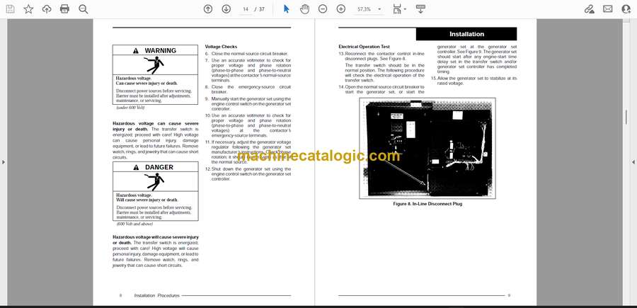
Electrical Operation Test . . . . . . . . . . . . . . . . . . . . . . . . . . . . . . . . . 9
Switch Position & Source Indicators . . . . . . . . . . . . . . . . . . . . . . . 11
Transfer Switch Position Lamps . . . . . . . . . . . . . . . . . . . . . . . . . . . . . . . . . . . . . . 11
Source Available Lamps . . . . . . . . . . . . . . . . . . . . . . . . . . . . . . . . . . . . . . . . . . . . . 11
Control Switches . . . . . . . . . . . . . . . . . . . . . . . . . . . . . . . . . . . . . . . . . . 11
“Transfer To”Normal-Emergency . . . . . . . . . . . . . . . . . . . . . . . . . . . . . . . . . . . . . 11
Generator Stop-Start (if equipped) . . . . . . . . . . . . . . . . . . . . . . . . . . . . . . . . . . . . 12
Alarm Silence Switch (if equipped) . . . . . . . . . . . . . . . . . . . . . . . . . . . . . . . . . . . . 12
Transfer Switch Operation . . . . . . . . . . . . . . . . . . . . . . . . . . . . . . . . . 12
Normal Power Loss . . . . . . . . . . . . . . . . . . . . . . . . . . . . . . . . . . . . . 12
Normal Power Return . . . . . . . . . . . . . . . . . . . . . . . . . . . . . . . . . . . . 13
Wiring Diagrams & Drawings . . . . . . . . . . . . . . . . . . . . . . . . . . . . . . 15
Interconnection Diagrams . . . . . . . . . . . . . . . . . . . . . . . . . . . . . . . . 15
Enclosure Dimensions . . . . . . . . . . . . . . . . . . . . . . . . . . . . . . . . . . . 15
Contactor Wiring . . . . . . . . . . . . . . . . . . . . . . . . . . . . . . . . . . . . . . . . 15
Schematics . . . . . . . . . . . . . . . . . . . . . . . . . . . . . . . . . . . . . . . . . . . . . 15
Wiring Diagrams . . . . . . . . . . . . . . . . . . . . . . . . . . . . . . . . . . . . . . . . 15


