Format: PDF (Printable Document)
File Language: English
File Pages: 92
File Size: 2.88 MB (Speed Download Link)
Brand: Kohler
Model: 350-2800 kW Industrial Generator Sets
Book No: tp5583
Type of Document: Service Manual
$ 40
These Kohler 350–2800 kW industrial generator sets usually sit in plants, hospitals, data centers, or large commercial buildings, picking up the load when the grid drops. This service manual is what I’d pull out when I need to trace a no-start condition, verify alarms, or tear into the mechanical and electrical sides in a logical order. For example, if a unit cranks but won’t come up to rated speed, this book walks you through the checks so you can confirm whether it’s a control issue, fuel problem, or a failed component before you start swapping parts.
Applications & Use Cases
FAQ
Q: Can I use this manual on a tablet in the field?
A: Yes, it’s practical to keep it on a tablet so you can zoom diagrams and search terms while standing at the generator.
Q: Is it worth printing sections of this manual?
A: Many techs print the procedures they’re using that day, so they can mark notes, oily fingerprints, and torque reminders right at the set.
Safety Note
Always lock out the generator and verify zero energy before opening panels or starting any hands-on troubleshooting.
Product Identification Information . . . . . . . . . . . . . . . . . . . . . . . . . . . . . . . . . . . . . . . . . . . . Inside front cover
Safety Precautions and Instructions . . . . . . . . . . . . . . . . . . . . . . . . . . . . . . . . . . . . . . . . . . . . . . . . . . . . . . . . I
Introduction . . . . . . . . . . . . . . . . . . . . . . . . . . . . . . . . . . . . . . . . . . . . . . . . . . . . . . . . . . . . . . . . . . . . . . . . . . . . . . . i
Service Assistance . . . . . . . . . . . . . . . . . . . . . . . . . . . . . . . . . . . . . . . . . . . . . . . . . . . . . . . . . . . . . . . . . . . . . . . . i
Section 1 Specifications . . . . . . . . . . . . . . . . . . . . . . . . . . . . . . . . . . . . . . . . . . . . . . . . . . . . . . . . . . . . . . . . . . . 1
1.1 Introduction . . . . . . . . . . . . . . . . . . . . . . . . . . . . . . . . . . . . . . . . . . . . . . . . . . . . . . . . . . 1
1.2 Specifications . . . . . . . . . . . . . . . . . . . . . . . . . . . . . . . . . . . . . . . . . . . . . . . . . . . . . . . . . 1
1.2.1 Generator . . . . . . . . . . . . . . . . . . . . . . . . . . . . . . . . . . . . . . . . . . . . . . . . . . . . 1
1.2.2 Engine . . . . . . . . . . . . . . . . . . . . . . . . . . . . . . . . . . . . . . . . . . . . . . . . . . . . . . . 2
1.3 Accessories . . . . . . . . . . . . . . . . . . . . . . . . . . . . . . . . . . . . . . . . . . . . . . . . . . . . . . . . . . 3
1.3.1 Remote Annunciator Kit (With Microprocessor Controller Only) . . . . . . 3
1.3.2 Audiovisual Alarm (With Microprocessor Controller Only) . . . . . . . . . . . 5
1.3.3 Ten-Relay Dry Contact Kit (With Microprocessor Controller Only) . . . . 5
1.3.4 Single-Relay Dry Contact Kit (With Microprocessor Controller Only) . . 6
1.3.5 Common Fault Relay Kit (With Microprocessor Controller Only) . . . . . . 6
1.3.6 Safeguard Breaker . . . . . . . . . . . . . . . . . . . . . . . . . . . . . . . . . . . . . . . . . . . . 6
1.3.7 Line Circuit Breaker . . . . . . . . . . . . . . . . . . . . . . . . . . . . . . . . . . . . . . . . . . . 6
1.3.8 Overvoltage Kit (With Microprocessor Controller Only) . . . . . . . . . . . . . . 7
1.3.9 Run Relay Kit . . . . . . . . . . . . . . . . . . . . . . . . . . . . . . . . . . . . . . . . . . . . . . . . . 7
1.3.10 Remote Emergency Stop Kit (With Microprocessor Controller Only) . . 7
1.3.11 Controller Connection Kit (With Microprocessor Controller Only) . . . . . 8
1.3.12 FASTCHECK Diagnostic Tester
(With Microprocessor Controller Only) . . . . . . . . . . . . . . . . . . . . . . . . . . . . 8
1.3.13 Accessory Connection (With Microprocessor Controller Only) . . . . . . . 8
Section 2 Operation . . . . . . . . . . . . . . . . . . . . . . . . . . . . . . . . . . . . . . . . . . . . . . . . . . . . . . . . . . . . . . . . . . . . . . . 11
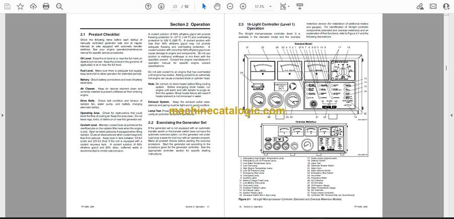
2.1 Prestart Checklist . . . . . . . . . . . . . . . . . . . . . . . . . . . . . . . . . . . . . . . . . . . . . . . . . . . . . 11
2.2 Exercising the Generator Set . . . . . . . . . . . . . . . . . . . . . . . . . . . . . . . . . . . . . . . . . . . 11
2.3 16-Light Controller (Level 1) Operation . . . . . . . . . . . . . . . . . . . . . . . . . . . . . . . . . . . 12
2.3.1 Features . . . . . . . . . . . . . . . . . . . . . . . . . . . . . . . . . . . . . . . . . . . . . . . . . . . . . 13
2.3.2 Starting . . . . . . . . . . . . . . . . . . . . . . . . . . . . . . . . . . . . . . . . . . . . . . . . . . . . . . 15
2.3.3 Stopping . . . . . . . . . . . . . . . . . . . . . . . . . . . . . . . . . . . . . . . . . . . . . . . . . . . . . 15
2.3.4 Resetting Emergency Stop Switches . . . . . . . . . . . . . . . . . . . . . . . . . . . . . 16
2.3.5 Fault Shutdowns . . . . . . . . . . . . . . . . . . . . . . . . . . . . . . . . . . . . . . . . . . . . . . 16
2.3.6 Controller Resetting Procedure (Following Fault Shutdown) . . . . . . . . . 17
2.4 6-Light Controller (Level 2) Operation . . . . . . . . . . . . . . . . . . . . . . . . . . . . . . . . . . . . 18
2.4.1 Features . . . . . . . . . . . . . . . . . . . . . . . . . . . . . . . . . . . . . . . . . . . . . . . . . . . . . 19
2.4.2 Starting . . . . . . . . . . . . . . . . . . . . . . . . . . . . . . . . . . . . . . . . . . . . . . . . . . . . . . 21
2.4.3 Stopping . . . . . . . . . . . . . . . . . . . . . . . . . . . . . . . . . . . . . . . . . . . . . . . . . . . . . 21
2.4.4 Resetting Emergency Stop Switches . . . . . . . . . . . . . . . . . . . . . . . . . . . . . 22
2.4.5 Fault Shutdowns . . . . . . . . . . . . . . . . . . . . . . . . . . . . . . . . . . . . . . . . . . . . . . 22
2.4.6 Controller Resetting Procedure (Following Fault Shutdown) . . . . . . . . . 23
2.5 Paralleling Engine Gauge Box Controller Operation (Switchgear) . . . . . . . . . . . . 23
Section 3 Scheduled Maintenance . . . . . . . . . . . . . . . . . . . . . . . . . . . . . . . . . . . . . . . . . . . . . . . . . . . . . . . . . . 25
3.1 Radiator Expansion Joint Loosening—Initial Startup only (Above 1000 kW) . . . 26
3.2 Fan Bearing Lubrication (Above 1000 kW) . . . . . . . . . . . . . . . . . . . . . . . . . . . . . . . . 26
3.3 Storage Procedure . . . . . . . . . . . . . . . . . . . . . . . . . . . . . . . . . . . . . . . . . . . . . . . . . . . . 27
Section 4 General Troubleshooting . . . . . . . . . . . . . . . . . . . . . . . . . . . . . . . . . . . . . . . . . . . . . . . . . . . . . . . . . 29
Table of Contents, continued
Table of Contents TP-5583 2/95
Section 5 Controller Troubleshooting . . . . . . . . . . . . . . . . . . . . . . . . . . . . . . . . . . . . . . . . . . . . . . . . . . . . . . . 31
5.1 Microprocessor Controller—Description . . . . . . . . . . . . . . . . . . . . . . . . . . . . . . . . . . 31
5.2 Fault Shutdowns— Microprocessor Controller . . . . . . . . . . . . . . . . . . . . . . . . . . . . . 38
5.3 Paralleling Engine Gauge Box Controller (Switchgear) . . . . . . . . . . . . . . . . . . . . . 39
5.3.1 Speed Switch Adjustments . . . . . . . . . . . . . . . . . . . . . . . . . . . . . . . . . . . . . 39
5.3.2 Crank Adjustment . . . . . . . . . . . . . . . . . . . . . . . . . . . . . . . . . . . . . . . . . . . . . 39
5.3.3 Overspeed Adjustment . . . . . . . . . . . . . . . . . . . . . . . . . . . . . . . . . . . . . . . . . 39
5.3.4 Troubleshooting . . . . . . . . . . . . . . . . . . . . . . . . . . . . . . . . . . . . . . . . . . . . . . . 39
Section 6 Generator/Controller Troubleshooting . . . . . . . . . . . . . . . . . . . . . . . . . . . . . . . . . . . . . . . . . . . . . 41
6.1 Microprocessor Controller . . . . . . . . . . . . . . . . . . . . . . . . . . . . . . . . . . . . . . . . . . . . . . 41
6.1.1 Relay Descriptions . . . . . . . . . . . . . . . . . . . . . . . . . . . . . . . . . . . . . . . . . . . . 41
6.1.2 Troubleshooting Microprocessor Controller . . . . . . . . . . . . . . . . . . . . . . . 42
6.2 FASTCHECK Features and Operation . . . . . . . . . . . . . . . . . . . . . . . . . . . . . . . . . . . 48
6.2.1 Features . . . . . . . . . . . . . . . . . . . . . . . . . . . . . . . . . . . . . . . . . . . . . . . . . . . . . 48
6.2.2 Indicator Lamps . . . . . . . . . . . . . . . . . . . . . . . . . . . . . . . . . . . . . . . . . . . . . . . 48
6.2.3 Switches . . . . . . . . . . . . . . . . . . . . . . . . . . . . . . . . . . . . . . . . . . . . . . . . . . . . . 49
6.2.4 Operation . . . . . . . . . . . . . . . . . . . . . . . . . . . . . . . . . . . . . . . . . . . . . . . . . . . . 49
6.2.5 Connect/Operate FASTCHECK Tester . . . . . . . . . . . . . . . . . . . . . . . . . . . 49
6.2.6 Overcrank . . . . . . . . . . . . . . . . . . . . . . . . . . . . . . . . . . . . . . . . . . . . . . . . . . . . 50
6.2.7 Controller Speed Sensor Circuitry . . . . . . . . . . . . . . . . . . . . . . . . . . . . . . . 50
6.2.8 Generator Condition Indicator Terminal (TB1 Terminal Strip) . . . . . . . . . 50
Section 7 Component Testing and Adjustment . . . . . . . . . . . . . . . . . . . . . . . . . . . . . . . . . . . . . . . . . . . . . . 53
7.1 Generator Troubleshooting . . . . . . . . . . . . . . . . . . . . . . . . . . . . . . . . . . . . . . . . . . . . . 53
7.2 Air Damper Switch Adjustment . . . . . . . . . . . . . . . . . . . . . . . . . . . . . . . . . . . . . . . . . . 53
7.3 Overvoltage Circuit Board . . . . . . . . . . . . . . . . . . . . . . . . . . . . . . . . . . . . . . . . . . . . . . 54
7.4 Governor Adjustment . . . . . . . . . . . . . . . . . . . . . . . . . . . . . . . . . . . . . . . . . . . . . . . . . . 56
7.4.1 Electronic Governor—Barber- Colman Dyna 8000/8200/ 8400,
350–2000 kW Detroit Diesel- Powered Models Without Ramp
Time Potentiometer . . . . . . . . . . . . . . . . . . . . . . . . . . . . . . . . . . . . . . . . . . . . 56
7.4.2 Electronic Governor—Barber- Colman Dyna 8000/8200/8400,
350–2000 kW Detroit Diesel- Powered Models With Ramp Time
Potentiometer . . . . . . . . . . . . . . . . . . . . . . . . . . . . . . . . . . . . . . . . . . . . . . . . . 57
Section 8 Generator Disassembly/Reassembly . . . . . . . . . . . . . . . . . . . . . . . . . . . . . . . . . . . . . . . . . . . . . . 61
8.1 Disassembly . . . . . . . . . . . . . . . . . . . . . . . . . . . . . . . . . . . . . . . . . . . . . . . . . . . . . . . . . . 62
8.2 Reassembly of Vibromount Models (20–450 kW) . . . . . . . . . . . . . . . . . . . . . . . . . . 62
8.3 Reassembly of Rigid Mount Models (500–2000 kW) . . . . . . . . . . . . . . . . . . . . . . . 63
8.3.1 All Models Rigid Mount Models
(Except 900/1000 kW with Detroit Diesel 24V-71TA Engine) . . . . . . . . . 63
8.3.2 Rigid Mount Models 900/1000 kW
with Detroit Diesel 24V-71TA Engine . . . . . . . . . . . . . . . . . . . . . . . . . . . . . 64
8.3.3 Prestart Test Sequence . . . . . . . . . . . . . . . . . . . . . . . . . . . . . . . . . . . . . . . . 65
Section 9 Generator Reconnection . . . . . . . . . . . . . . . . . . . . . . . . . . . . . . . . . . . . . . . . . . . . . . . . . . . . . . . . . 67
9.1 Voltage Reconnection Procedure . . . . . . . . . . . . . . . . . . . . . . . . . . . . . . . . . . . . . . . . 67
9.2 Generator Frequency Change and Adjustment . . . . . . . . . . . . . . . . . . . . . . . . . . . . 69
9.2.1 Frequency Change . . . . . . . . . . . . . . . . . . . . . . . . . . . . . . . . . . . . . . . . . . . . 69
9.2.2 Frequency Adjustment . . . . . . . . . . . . . . . . . . . . . . . . . . . . . . . . . . . . . . . . . 69
Appendix A Abbreviations . . . . . . . . . . . . . . . . . . . . . . . . . . . . . . . . . . . . . . . . . . . . . . . . . . . . . . . . . . . . . . . . A-1
Appendix B Common Hardware Application Guidelines . . . . . . . . . . . . . . . . . . . . . . . . . . . . . . . . . . . . . A-3
Appendix C General Torque Specifications . . . . . . . . . . . . . . . . . . . . . . . . . . . . . . . . . . . . . . . . . . . . . . . . . A-4
Appendix D Common Hardware Identification . . . . . . . . . . . . . . . . . . . . . . . . . . . . . . . . . . . . . . . . . . . . . . A


