Format: PDF (Printable Document)
File Language: English
File Pages: 136
File Size: 5.92 MB (Speed Download Link)
Brand: Kohler
Model: 6EKOD, 5EFKOD, 9-11EKOZD, 7-9EFKOZD Marine
Book No: tp6774
Type of Document: Service Manual
$ 40
On these Kohler marine gensets, you’re dealing with engines that sit in hot, cramped engine rooms, feeding power to onboard systems hour after hour. This service manual is what I reach for when I need to prove what’s actually failed before I start throwing parts at it. Say the set starts hunting under load or won’t carry the air‑conditioning—this book walks you through the checks to trace whether it’s fuel, governor, electrical, or a simple adjustment issue.
Applications & Use Cases
FAQ
Q: Can I keep this manual on a tablet in the engine room?
A: Yes, it’s practical to use digitally; you can zoom wiring diagrams and procedures while working in tight spaces.
Q: Should I still print parts of it?
A: Many techs print key procedures or diagrams so they can mark notes, keep them clean in sheet protectors, and tape them near the job.
Safety Note
Always lock out the generator and verify no backfeed before opening covers or disconnecting any wiring.
Safety Precautions and Instructions . . . . . . . . . . . . . . . . . . . . . . . . . . . . . . . . . . . . . . . . . . . . . . . . . . . . . . . . 7
Introduction . . . . . . . . . . . . . . . . . . . . . . . . . . . . . . . . . . . . . . . . . . . . . . . . . . . . . . . . . . . . . . . . . . . . . . . . . . . . . . 11
Service Assistance . . . . . . . . . . . . . . . . . . . . . . . . . . . . . . . . . . . . . . . . . . . . . . . . . . . . . . . . . . . . . . . . . . . . . . . . 11
Section 1 Specifications . . . . . . . . . . . . . . . . . . . . . . . . . . . . . . . . . . . . . . . . . . . . . . . . . . . . . . . . . . . . . . . . . . . 13
1.1 General . . . . . . . . . . . . . . . . . . . . . . . . . . . . . . . . . . . . . . . . . . . . . . . . . . . . . . . . . . . . . . 13
1.2 Engine . . . . . . . . . . . . . . . . . . . . . . . . . . . . . . . . . . . . . . . . . . . . . . . . . . . . . . . . . . . . . . 14
1.3 Generator, 4 Lead . . . . . . . . . . . . . . . . . . . . . . . . . . . . . . . . . . . . . . . . . . . . . . . . . . . . . 15
1.4 Generator, 12 Lead . . . . . . . . . . . . . . . . . . . . . . . . . . . . . . . . . . . . . . . . . . . . . . . . . . . . 15
1.5 Service Views . . . . . . . . . . . . . . . . . . . . . . . . . . . . . . . . . . . . . . . . . . . . . . . . . . . . . . . . 16
1.6 Torque Specifications . . . . . . . . . . . . . . . . . . . . . . . . . . . . . . . . . . . . . . . . . . . . . . . . . . 17
Section 2 Scheduled Maintenance . . . . . . . . . . . . . . . . . . . . . . . . . . . . . . . . . . . . . . . . . . . . . . . . . . . . . . . . . . 19
2.1 General . . . . . . . . . . . . . . . . . . . . . . . . . . . . . . . . . . . . . . . . . . . . . . . . . . . . . . . . . . . . . . 19
2.2 Lubrication System . . . . . . . . . . . . . . . . . . . . . . . . . . . . . . . . . . . . . . . . . . . . . . . . . . . . 20
Section 3 Exhaust System . . . . . . . . . . . . . . . . . . . . . . . . . . . . . . . . . . . . . . . . . . . . . . . . . . . . . . . . . . . . . . . . . 21
3.1 Exhaust System Inspection . . . . . . . . . . . . . . . . . . . . . . . . . . . . . . . . . . . . . . . . . . . . . 21
3.2 Servicing Mixing Elbow . . . . . . . . . . . . . . . . . . . . . . . . . . . . . . . . . . . . . . . . . . . . . . . . 21
Section 4 Fuel System . . . . . . . . . . . . . . . . . . . . . . . . . . . . . . . . . . . . . . . . . . . . . . . . . . . . . . . . . . . . . . . . . . . . 23
4.1 General . . . . . . . . . . . . . . . . . . . . . . . . . . . . . . . . . . . . . . . . . . . . . . . . . . . . . . . . . . . . . . 23
4.2 Fuel Filter . . . . . . . . . . . . . . . . . . . . . . . . . . . . . . . . . . . . . . . . . . . . . . . . . . . . . . . . . . . . 23
4.2.1 Fuel System Bleed . . . . . . . . . . . . . . . . . . . . . . . . . . . . . . . . . . . . . . . . . . . . 24
4.3 Fuel Pump . . . . . . . . . . . . . . . . . . . . . . . . . . . . . . . . . . . . . . . . . . . . . . . . . . . . . . . . . . . 25
4.4 Governor . . . . . . . . . . . . . . . . . . . . . . . . . . . . . . . . . . . . . . . . . . . . . . . . . . . . . . . . . . . . 25
4.5 Fuel Solenoid . . . . . . . . . . . . . . . . . . . . . . . . . . . . . . . . . . . . . . . . . . . . . . . . . . . . . . . . . 25
Section 5 Cooling System . . . . . . . . . . . . . . . . . . . . . . . . . . . . . . . . . . . . . . . . . . . . . . . . . . . . . . . . . . . . . . . . . 27
5.1 General . . . . . . . . . . . . . . . . . . . . . . . . . . . . . . . . . . . . . . . . . . . . . . . . . . . . . . . . . . . . . . 27
5.2 Water-Cooled Exhaust Manifold . . . . . . . . . . . . . . . . . . . . . . . . . . . . . . . . . . . . . . . . . 28
5.3 Coolant Replacement Including Heat Exchanger Service . . . . . . . . . . . . . . . . . . . 28
5.4 Check and Fill Coolant . . . . . . . . . . . . . . . . . . . . . . . . . . . . . . . . . . . . . . . . . . . . . . . . . 31
5.5 Flush and Clean Cooling System . . . . . . . . . . . . . . . . . . . . . . . . . . . . . . . . . . . . . . . . 32
5.6 Pressure Cap . . . . . . . . . . . . . . . . . . . . . . . . . . . . . . . . . . . . . . . . . . . . . . . . . . . . . . . . 32
5.7 Impeller Inspection and Replacement . . . . . . . . . . . . . . . . . . . . . . . . . . . . . . . . . . . . 32
5.8 Belt Tension . . . . . . . . . . . . . . . . . . . . . . . . . . . . . . . . . . . . . . . . . . . . . . . . . . . . . . . . . . 33
5.8.1 Seawater Pump Belt Tensioning Procedure . . . . . . . . . . . . . . . . . . . . . . . 33
5.9 Anticorrosion Zinc Anode . . . . . . . . . . . . . . . . . . . . . . . . . . . . . . . . . . . . . . . . . . . . . . 34
5.10 Siphon Break . . . . . . . . . . . . . . . . . . . . . . . . . . . . . . . . . . . . . . . . . . . . . . . . . . . . . . . . . 35
Section 6 Troubleshooting . . . . . . . . . . . . . . . . . . . . . . . . . . . . . . . . . . . . . . . . . . . . . . . . . . . . . . . . . . . . . . . . 37
6.1 Introduction . . . . . . . . . . . . . . . . . . . . . . . . . . . . . . . . . . . . . . . . . . . . . . . . . . . . . . . . . . 37
6.2 Initial Checks . . . . . . . . . . . . . . . . . . . . . . . . . . . . . . . . . . . . . . . . . . . . . . . . . . . . . . . . . 37
6.3 Troubleshooting Chart . . . . . . . . . . . . . . . . . . . . . . . . . . . . . . . . . . . . . . . . . . . . . . . . . 37
Section 7 Controller . . . . . . . . . . . . . . . . . . . . . . . . . . . . . . . . . . . . . . . . . . . . . . . . . . . . . . . . . . . . . . . . . . . . . . . 43
7.1 Introduction . . . . . . . . . . . . . . . . . . . . . . . . . . . . . . . . . . . . . . . . . . . . . . . . . . . . . . . . . . 43
7.2 General Repair Information . . . . . . . . . . . . . . . . . . . . . . . . . . . . . . . . . . . . . . . . . . . . . 44
7.3 SiteTecht Software . . . . . . . . . . . . . . . . . . . . . . . . . . . . . . . . . . . . . . . . . . . . . . . . . . . 45
7.4 Controller Service Replacement Kit GM83745 . . . . . . . . . . . . . . . . . . . . . . . . . . . . . 45
7.5 Advanced Digital Control IId Operation . . . . . . . . . . . . . . . . . . . . . . . . . . . . . . . . . . . 47
7.5.1 Controls and Indicators . . . . . . . . . . . . . . . . . . . . . . . . . . . . . . . . . . . . . . . . 47
7.5.2 Starting the Generator Set . . . . . . . . . . . . . . . . . . . . . . . . . . . . . . . . . . . . . . 48
7.5.3 Stopping the Generator Set . . . . . . . . . . . . . . . . . . . . . . . . . . . . . . . . . . . . . 49
7.5.4 Fault Shutdowns and Warnings . . . . . . . . . . . . . . . . . . . . . . . . . . . . . . . . . 49
7.5.5 Digital Display . . . . . . . . . . . . . . . . . . . . . . . . . . . . . . . . . . . . . . . . . . . . . . . . 51
4 Table of Contents TP-6774 3/19c
7.5.6 Controller Fault Diagnostics . . . . . . . . . . . . . . . . . . . . . . . . . . . . . . . . . . . . 53
7.6 Communication Port . . . . . . . . . . . . . . . . . . . . . . . . . . . . . . . . . . . . . . . . . . . . . . . . . . . 55
7.7 Fuses . . . . . . . . . . . . . . . . . . . . . . . . . . . . . . . . . . . . . . . . . . . . . . . . . . . . . . . . . . . . . . . 55
7.8 Preheat Relay . . . . . . . . . . . . . . . . . . . . . . . . . . . . . . . . . . . . . . . . . . . . . . . . . . . . . . . . 55
7.9 Battery Charging Module, Original (GM77373) . . . . . . . . . . . . . . . . . . . . . . . . . . . . 56
7.10 Battery Charging Module, Revised (GM105398) . . . . . . . . . . . . . . . . . . . . . . . . . . . 56
7.10.1 Three Stage Charge Cycle . . . . . . . . . . . . . . . . . . . . . . . . . . . . . . . . . . . . . 56
7.10.2 Protection Modes . . . . . . . . . . . . . . . . . . . . . . . . . . . . . . . . . . . . . . . . . . . . . 57
7.10.3 Charger Operation . . . . . . . . . . . . . . . . . . . . . . . . . . . . . . . . . . . . . . . . . . . . 57
7.10.4 Charger Troubleshooting . . . . . . . . . . . . . . . . . . . . . . . . . . . . . . . . . . . . . . . 58
7.11 Controller Logic Specifications . . . . . . . . . . . . . . . . . . . . . . . . . . . . . . . . . . . . . . . . . . 58
7.11.1 Fault Shutdown and Warning Specifications . . . . . . . . . . . . . . . . . . . . . . 58
7.11.2 Controller Resetting (Following System Fault Shutdown) . . . . . . . . . . . 63
7.11.3 Voltage Regulator and Calibration Specifications . . . . . . . . . . . . . . . . . . 63
7.11.4 Voltage Regulator Adjustments . . . . . . . . . . . . . . . . . . . . . . . . . . . . . . . . . 63
7.11.5 System Fault Warning Lamp with Digital Displays . . . . . . . . . . . . . . . . . . 64
7.11.6 System Fault Shutdown Lamp With Digital Displays . . . . . . . . . . . . . . . . 65
7.11.7 Status and Notice Digital Displays . . . . . . . . . . . . . . . . . . . . . . . . . . . . . . . 66
7.12 Menu Displays . . . . . . . . . . . . . . . . . . . . . . . . . . . . . . . . . . . . . . . . . . . . . . . . . . . . . . . . 67
7.13 Monitoring and Programming Setup . . . . . . . . . . . . . . . . . . . . . . . . . . . . . . . . . . . . . 69
7.13.1 PC Communications . . . . . . . . . . . . . . . . . . . . . . . . . . . . . . . . . . . . . . . . . . . 69
7.14 Reviewing Menu Displays . . . . . . . . . . . . . . . . . . . . . . . . . . . . . . . . . . . . . . . . . . . . . . 69
7.14.1 Error Messages . . . . . . . . . . . . . . . . . . . . . . . . . . . . . . . . . . . . . . . . . . . . . . . 69
7.14.2 Overview . . . . . . . . . . . . . . . . . . . . . . . . . . . . . . . . . . . . . . . . . . . . . . . . . . . . 70
7.14.3 Engine Metering . . . . . . . . . . . . . . . . . . . . . . . . . . . . . . . . . . . . . . . . . . . . . . 70
7.14.4 Generator Metering (and Calibration) . . . . . . . . . . . . . . . . . . . . . . . . . . . . 71
7.14.5 GenSet Information . . . . . . . . . . . . . . . . . . . . . . . . . . . . . . . . . . . . . . . . . . . . 72
7.14.6 GenSet Run Time . . . . . . . . . . . . . . . . . . . . . . . . . . . . . . . . . . . . . . . . . . . . . 72
7.14.7 GenSet System . . . . . . . . . . . . . . . . . . . . . . . . . . . . . . . . . . . . . . . . . . . . . . . 72
7.14.8 Voltage Regulator . . . . . . . . . . . . . . . . . . . . . . . . . . . . . . . . . . . . . . . . . . . . . 73
7.14.9 Event Log . . . . . . . . . . . . . . . . . . . . . . . . . . . . . . . . . . . . . . . . . . . . . . . . . . . . 73
7.14.10 Prime Menu . . . . . . . . . . . . . . . . . . . . . . . . . . . . . . . . . . . . . . . . . . . . . . . . . . 74
7.14.11 Volt Select . . . . . . . . . . . . . . . . . . . . . . . . . . . . . . . . . . . . . . . . . . . . . . . . . . . 74
7.14.12 USB Flowchart . . . . . . . . . . . . . . . . . . . . . . . . . . . . . . . . . . . . . . . . . . . . . . . 75
Section 8 Component Testing and Adjustment . . . . . . . . . . . . . . . . . . . . . . . . . . . . . . . . . . . . . . . . . . . . . . 77
8.1 Theory of Operation . . . . . . . . . . . . . . . . . . . . . . . . . . . . . . . . . . . . . . . . . . . . . . . . . . . 77
8.2 Separate Excitation . . . . . . . . . . . . . . . . . . . . . . . . . . . . . . . . . . . . . . . . . . . . . . . . . . . 77
8.3 Exciter Field (9- 11EKOZD/7- 9EFKOZD Models) . . . . . . . . . . . . . . . . . . . . . . . . . . 79
8.4 Exciter Armature (9- 11EKOZD and 7- 9EFKOZD Models) . . . . . . . . . . . . . . . . . . 80
8.5 Slip Rings (6EKOD/5EFKOD Models) . . . . . . . . . . . . . . . . . . . . . . . . . . . . . . . . . . . . 81
8.6 Brushes (6EKOD/5EFKOD Models) . . . . . . . . . . . . . . . . . . . . . . . . . . . . . . . . . . . . . 81
8.7 Rectifier Module (9- 11EKOZD and 7- 9EFKOZD Models) . . . . . . . . . . . . . . . . . . . 82
8.8 Rotor . . . . . . . . . . . . . . . . . . . . . . . . . . . . . . . . . . . . . . . . . . . . . . . . . . . . . . . . . . . . . . . . 82
8.9 Stator . . . . . . . . . . . . . . . . . . . . . . . . . . . . . . . . . . . . . . . . . . . . . . . . . . . . . . . . . . . . . . . 83
8.10 Voltage Regulator . . . . . . . . . . . . . . . . . . . . . . . . . . . . . . . . . . . . . . . . . . . . . . . . . . . . . 85
8.10.1 Voltage Regulator and Calibration Specifications . . . . . . . . . . . . . . . . . . 85
8.10.2 Voltage Regulator Adjustments . . . . . . . . . . . . . . . . . . . . . . . . . . . . . . . . . 85
8.10.3 Voltage Regulator . . . . . . . . . . . . . . . . . . . . . . . . . . . . . . . . . . . . . . . . . . . . . 86
8.11 Voltage Reconnection . . . . . . . . . . . . . . . . . . . . . . . . . . . . . . . . . . . . . . . . . . . . . . . . . 87
8.12 Four-Lead Reconnection . . . . . . . . . . . . . . . . . . . . . . . . . . . . . . . . . . . . . . . . . . . . . . . 89
8.12.1 100- 120-Volt Configurations . . . . . . . . . . . . . . . . . . . . . . . . . . . . . . . . . . . . 89
8.12.2 100- 120/200- 240-Volt Configurations . . . . . . . . . . . . . . . . . . . . . . . . . . . 89
8.12.3 200- 240-Volt Configurations . . . . . . . . . . . . . . . . . . . . . . . . . . . . . . . . . . . . 90
8.13 Twelve-Lead Reconnection . . . . . . . . . . . . . . . . . . . . . . . . . . . . . . . . . . . . . . . . . . . . . 90
8.14 Fault Shutdown Tests . . . . . . . . . . . . . . . . . . . . . . . . . . . . . . . . . . . . . . . . . . . . . . . . . . 91
8.14.1 Controller Fault Shutdown Functions . . . . . . . . . . . . . . . . . . . . . . . . . . . . . 91
8.14.2 Fault Shutdown Senders/Switches . . . . . . . . . . . . . . . . . . . . . . . . . . . . . . 92
8.15 Fuses . . . . . . . . . . . . . . . . . . . . . . . . . . . . . . . . . . . . . . . . . . . . . . . . . . . . . . . . . . . . . . . 93
Disassembly/Reassembly . . . . . . . . . . . . . . . . . . . . . . . . . . . . . . . . . . . . . . . . . . . . . . 95
9.1 Disassembly . . . . . . . . . . . . . . . . . . . . . . . . . . . . . . . . . . . . . . . . . . . . . . . . . . . . . . . . . 95
9.2 Collector Ring and Bearing Replacement (6EKOD/5EFKOD Model) . . . . . . . . . . 102
9.3 Reassembly . . . . . . . . . . . . . . . . . . . . . . . . . . . . . . . . . . . . . . . . . . . . . . . . . . . . . . . . . . 102
Section 10 Wiring Diagrams . . . . . . . . . . . . . . . . . . . . . . . . . . . . . . . . . . . . . . . . . . . . . . . . . . . . . . . . . . . . . . . 105
10.1 Wiring Diagram Reference . . . . . . . . . . . . . . . . . . . . . . . . . . . . . . . . . . . . . . . . . . . . . 105
10.2 Manual Marine (Ship-to-Shore) 2 Wire and 3 Wire Transfer Switches . . . . . . . . . 122
10.3 Manual Marine (Ship-to-Shore) 4 Wire Transfer Switch . . . . . . . . . . . . . . . . . . . . . 123
Appendix A Abbreviations . . . . . . . . . . . . . . . . . . . . . . . . . . . . . . . . . . . . . . . . . . . . . . . . . . . . . . . . . . . . . . . . 125
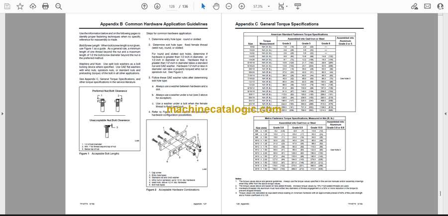
Appendix B Common Hardware Application Guidelines . . . . . . . . . . . . . . . . . . . . . . . . . . . . . . . . . . . . . 127
Appendix C General Torque Specifications . . . . . . . . . . . . . . . . . . . . . . . . . . . . . . . . . . . . . . . . . . . . . . . . 128
Appendix D Common Hardware Identification . . . . . . . . . . . . . . . . . . . . . . . . . . . . . . . . . . . . . . . . . . . . . . 129
Appendix E Common Hardware List . . . . . . . . . . . . . . . . . . . . . . . . . . . . . . . . . . . . . . . . . . . . . . . . . . . . . . . 130


