Format: PDF (Printable Document)
File Language: English
File Pages: 64
File Size: 0.90 MB (Speed Download Link)
Brand: Kohler
Model: G-GN, GLS-GLN, GTS-GTN Automatic Transfer Switches
Book No: tp5995
Type of Document: Service Parts Manual
$ 40
These Kohler automatic transfer switches sit between your utility and generator, usually in plant rooms, hospitals, data centers, or commercial buildings, and quietly handle the load transfer when the power drops. This service parts manual is what I use to match every relay, coil, contact kit, and mechanical linkage in those G/GN, GLS/GLN, and GTS/GTN switches to the correct Kohler part number. When a switch is chattering, won’t re-transfer, or has heat-damaged contacts, this book lets me identify exactly which pieces to replace before I even open the panel.
Applications & Use Cases
FAQ
Q: Can I use this manual on a tablet or phone at the switchgear?
A: Yes, a PDF copy works well; you can zoom in on diagrams to confirm small hardware and terminal layouts right at the cabinet.
Q: Is it worth printing sections of this manual?
A: I usually print the pages for the exact switch model on site and keep them in a plastic sleeve inside the ATS enclosure for quick reference.
Safety Note
Always isolate all power sources and verify the switch is de-energized before opening covers or handling any internal parts.
Introduction . . . . . . . . . . . . . . . . . . . . . . . . . . . . . . . . . . . . . . . . . . . . . . . . . . . . . . . . . . . . . . . . . . . . . . . . . . . . . . . 1
Nameplate . . . . . . . . . . . . . . . . . . . . . . . . . . . . . . . . . . . . . . . . . . . . . . . . . . . . . . . . . . . . . . . . . 1
Model Designation . . . . . . . . . . . . . . . . . . . . . . . . . . . . . . . . . . . . . . . . . . . . . . . . . . . . . . . . . . 1
Finding Part Numbers . . . . . . . . . . . . . . . . . . . . . . . . . . . . . . . . . . . . . . . . . . . . . . . . . . . . . . . 3
Service Parts . . . . . . . . . . . . . . . . . . . . . . . . . . . . . . . . . . . . . . . . . . . . . . . . . 3
Enclosures . . . . . . . . . . . . . . . . . . . . . . . . . . . . . . . . . . . . . . . . . . . . . . . . . . . 3
Contactor Assemblies . . . . . . . . . . . . . . . . . . . . . . . . . . . . . . . . . . . . . . . . . . 3
Accessories . . . . . . . . . . . . . . . . . . . . . . . . . . . . . . . . . . . . . . . . . . . . . . . . . . 3
Leads . . . . . . . . . . . . . . . . . . . . . . . . . . . . . . . . . . . . . . . . . . . . . . . . . . . . . . . . . . . . . . . . . . . . . 3
Common Hardware . . . . . . . . . . . . . . . . . . . . . . . . . . . . . . . . . . . . . . . . . . . . . . . . . . . . . . . . . 3
Service Parts, Main Unit . . . . . . . . . . . . . . . . . . . . . . . . . . . . . . . . . . . . . . . . . . . . . . . . . . . . . . . . . . . . . . . . . . . . 4
Enclosure, S340 Controls . . . . . . . . . . . . . . . . . . . . . . . . . . . . . . . . . . . . . . . . . . . . . . . . . . . . 4
Enclosure, M340 Controls . . . . . . . . . . . . . . . . . . . . . . . . . . . . . . . . . . . . . . . . . . . . . . . . . . . 6
Inner Panel, S340 Controls . . . . . . . . . . . . . . . . . . . . . . . . . . . . . . . . . . . . . . . . . . . . . . . . . . 8
Controller Board, S340 Controls . . . . . . . . . . . . . . . . . . . . . . . . . . . . . . . . . 10
Transformer, S340 Controls . . . . . . . . . . . . . . . . . . . . . . . . . . . . . . . . . . . . . 11
Inner Panel, M340 Controls . . . . . . . . . . . . . . . . . . . . . . . . . . . . . . . . . . . . . . . . . . . . . . . . . . 12
Controller Board, M340 Controls . . . . . . . . . . . . . . . . . . . . . . . . . . . . . . . . 14
Transformer, M340 Controls . . . . . . . . . . . . . . . . . . . . . . . . . . . . . . . . . . . . 15
Neutral Lugs . . . . . . . . . . . . . . . . . . . . . . . . . . . . . . . . . . . . . . . . . . . . . . . . . . . . . . . . . . . . . . . 16
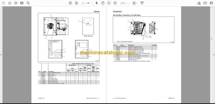
Decals . . . . . . . . . . . . . . . . . . . . . . . . . . . . . . . . . . . . . . . . . . . . . . . . . . . . . . . . . . . . . . . . . . . . 17
Contactors . . . . . . . . . . . . . . . . . . . . . . . . . . . . . . . . . . . . . . . . . . . . . . . . . . . . . . . . . . . . . . . . . 18
250 Volt Max. Contactors, 40–200 Amps . . . . . . . . . . . . . . . . . . . . . . . . . 18
600 Volt Max. Contactors, 40–150 Amps . . . . . . . . . . . . . . . . . . . . . . . . . 20
600 Volt Max. Contactors, 225–400 Amps . . . . . . . . . . . . . . . . . . . . . . . . 23
Service Parts, Accessories . . . . . . . . . . . . . . . . . . . . . . . . . . . . . . . . . . . . . . . . . . . . . . . . . . . . . . . . . . . . . . . . . 27
Appendix A Abbreviations . . . . . . . . . . . . . . . . . . . . . . . . . . . . . . . . . . . . . . . . . . . . . . . . . . . . . . . . . . . . . . . . . . A-1
Appendix B Common Hardware Application Guidelines . . . . . . . . . . . . . . . . . . . . . . . . . . . . . . . . . . . . . . . . A-3
Appendix C General Torque Specifications . . . . . . . . . . . . . . . . . . . . . . . . . . . . . . . . . . . . . . . . . . . . . . . . . . . A-4
Appendix D Common Hardware Identification . . . . . . . . . . . . . . . . . . . . . . . . . . . . . . . . . . . . . . . . . . . . . . . . . A-5
Appendix E Common Hardware List . . . . . . . . . . . . . . . . . . . . . . . . . . . . . . . . . . . . . . . . . . . . . . . . . . . . . . . . . A-6


