Format: PDF (Printable Document)
File Language: English
File Pages: 80
File Size: 3.56 MB (Speed Download Link)
Brand: Kohler
Model: KBS, KBP, KBC Automatic Transfer and Bypass, Isolation Switches
Book No: tp6835
Type of Document: Operation and Installation Manual
$ 40
These Kohler automatic transfer and bypass/isolation switches usually sit in electrical rooms or generator enclosures, quietly handling the changeover between utility and standby power. This manual is what I’d keep on hand when installing, setting up, or checking one that’s not transferring the load the way it should. For example, if a customer says the generator starts but the building never picks up on standby, this document walks you through how to verify the switch position, confirm operating sequence, and correct basic installation or setup issues.
Applications & Use Cases
FAQ
Q: Can I keep this manual on a tablet or phone in the electrical room?
A: Yes, it’s practical to use digitally; you can zoom in on diagrams and search terms while you’re in front of the gear.
Q: Should I still print a copy for the jobsite?
A: I recommend a printed copy in a plastic sleeve inside the switch cabinet, so anyone servicing it later has the instructions right there.
Safety Note
Always de-energize and lock out all sources before opening, adjusting, or working inside these switches.
Safety Precautions and Instructions . . . . . . . . . . . . . . . . . . . . . . . . . . . . . . . . . . . . . . . . . . . . . . . . . . . . . . . . . 5
Introduction . . . . . . . . . . . . . . . . . . . . . . . . . . . . . . . . . . . . . . . . . . . . . . . . . . . . . . . . . . . . . . . . . . . . . . . . . . . . . . . 7
List of Related Materials . . . . . . . . . . . . . . . . . . . . . . . . . . . . . . . . . . . . . . . . . . . . . . . . . . . . . . 7
Service Assistance . . . . . . . . . . . . . . . . . . . . . . . . . . . . . . . . . . . . . . . . . . . . . . . . . . . . . . . . . . . . . . . . . . . . . . . . . 8
Section 1 Product Description . . . . . . . . . . . . . . . . . . . . . . . . . . . . . . . . . . . . . . . . . . . . . . . . . . . . . . . . . . . . . . 9
1.1 Purpose . . . . . . . . . . . . . . . . . . . . . . . . . . . . . . . . . . . . . . . . . . . . . . . . . . . . . . . . . . . . . . 9
1.2 Nameplate . . . . . . . . . . . . . . . . . . . . . . . . . . . . . . . . . . . . . . . . . . . . . . . . . . . . . . . . . . . . 9
1.3 Model Designation . . . . . . . . . . . . . . . . . . . . . . . . . . . . . . . . . . . . . . . . . . . . . . . . . . . . . 10
Section 2 Installation . . . . . . . . . . . . . . . . . . . . . . . . . . . . . . . . . . . . . . . . . . . . . . . . . . . . . . . . . . . . . . . . . . . . . . 11
2.1 Introduction . . . . . . . . . . . . . . . . . . . . . . . . . . . . . . . . . . . . . . . . . . . . . . . . . . . . . . . . . . . 11
2.2 Receipt of Unit . . . . . . . . . . . . . . . . . . . . . . . . . . . . . . . . . . . . . . . . . . . . . . . . . . . . . . . . 11
2.2.1 Inspection . . . . . . . . . . . . . . . . . . . . . . . . . . . . . . . . . . . . . . . . . . . . . . . . . . . . 11
2.2.2 Lifting . . . . . . . . . . . . . . . . . . . . . . . . . . . . . . . . . . . . . . . . . . . . . . . . . . . . . . . . 11
2.2.3 Storage . . . . . . . . . . . . . . . . . . . . . . . . . . . . . . . . . . . . . . . . . . . . . . . . . . . . . . 12
2.2.4 Unpacking . . . . . . . . . . . . . . . . . . . . . . . . . . . . . . . . . . . . . . . . . . . . . . . . . . . . 12
2.3 Installation . . . . . . . . . . . . . . . . . . . . . . . . . . . . . . . . . . . . . . . . . . . . . . . . . . . . . . . . . . . . 13
2.4 IBC Seismic Certification or California OSHPD Approval . . . . . . . . . . . . . . . . . . . . 14
2.5 Manual Operation Check . . . . . . . . . . . . . . . . . . . . . . . . . . . . . . . . . . . . . . . . . . . . . . . 15
2.5.1 Manual Operation, 150–4000 Amp Standard-Transition Model KBS . . 16
2.5.2 Manual Operation, 150–4000 Amp Programmed- and Closed-
Transition Models KBP and KBC . . . . . . . . . . . . . . . . . . . . . . . . . . . . . . . . . 17
2.6 Controller Connections . . . . . . . . . . . . . . . . . . . . . . . . . . . . . . . . . . . . . . . . . . . . . . . . . 18
2.6.1 Controller Input and Output Connections . . . . . . . . . . . . . . . . . . . . . . . . . . 19
2.6.2 Harness Connection . . . . . . . . . . . . . . . . . . . . . . . . . . . . . . . . . . . . . . . . . . . 19
2.6.3 Controller Ground . . . . . . . . . . . . . . . . . . . . . . . . . . . . . . . . . . . . . . . . . . . . . . 19
2.7 Electrical Wiring . . . . . . . . . . . . . . . . . . . . . . . . . . . . . . . . . . . . . . . . . . . . . . . . . . . . . . . 20
2.7.1 Source and Load Connections . . . . . . . . . . . . . . . . . . . . . . . . . . . . . . . . . . . 20
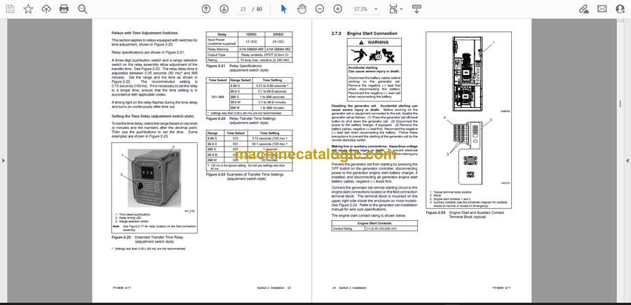
2.7.2 Extended Transfer Time Relay (Model KBC only) . . . . . . . . . . . . . . . . . . 22
2.7.3 Engine Start Connection . . . . . . . . . . . . . . . . . . . . . . . . . . . . . . . . . . . . . . . . 24
2.7.4 Auxiliary Contacts . . . . . . . . . . . . . . . . . . . . . . . . . . . . . . . . . . . . . . . . . . . . . 25
2.8 Communication and Accessory Connections . . . . . . . . . . . . . . . . . . . . . . . . . . . . . . 25
2.9 Functional Tests . . . . . . . . . . . . . . . . . . . . . . . . . . . . . . . . . . . . . . . . . . . . . . . . . . . . . . . 25
Section 3 Three-Source Systems . . . . . . . . . . . . . . . . . . . . . . . . . . . . . . . . . . . . . . . . . . . . . . . . . . . . . . . . . . . 27
3.1 Three-Source Systems . . . . . . . . . . . . . . . . . . . . . . . . . . . . . . . . . . . . . . . . . . . . . . . . . 27
3.2 Three Source Engine Start Mode . . . . . . . . . . . . . . . . . . . . . . . . . . . . . . . . . . . . . . . . 27
3.2.1 Mode 1 . . . . . . . . . . . . . . . . . . . . . . . . . . . . . . . . . . . . . . . . . . . . . . . . . . . . . . . 27
3.2.2 Mode 2 . . . . . . . . . . . . . . . . . . . . . . . . . . . . . . . . . . . . . . . . . . . . . . . . . . . . . . . 27
3.3 Preferred Source Toggle . . . . . . . . . . . . . . . . . . . . . . . . . . . . . . . . . . . . . . . . . . . . . . . . 27
3.4 Three Source System Test and Exercise . . . . . . . . . . . . . . . . . . . . . . . . . . . . . . . . . . 27
3.4.1 Unloaded Test . . . . . . . . . . . . . . . . . . . . . . . . . . . . . . . . . . . . . . . . . . . . . . . . . 27
3.4.2 Loaded Test . . . . . . . . . . . . . . . . . . . . . . . . . . . . . . . . . . . . . . . . . . . . . . . . . . . 27
3.4.3 Unloaded Exercise . . . . . . . . . . . . . . . . . . . . . . . . . . . . . . . . . . . . . . . . . . . . . 27
3.4.4 Loaded Exercise . . . . . . . . . . . . . . . . . . . . . . . . . . . . . . . . . . . . . . . . . . . . . . . 27
3.5 Three-Source System Connection . . . . . . . . . . . . . . . . . . . . . . . . . . . . . . . . . . . . . . . 28
3.6 ATS1 and ATS2 System Setup . . . . . . . . . . . . . . . . . . . . . . . . . . . . . . . . . . . . . . . . . . 30
Section 4 Communication and Accessory Connections . . . . . . . . . . . . . . . . . . . . . . . . . . . . . . . . . . . . . . 31
4.1 Introduction . . . . . . . . . . . . . . . . . . . . . . . . . . . . . . . . . . . . . . . . . . . . . . . . . . . . . . . . . . . 31
4.2 Communication Connections . . . . . . . . . . . . . . . . . . . . . . . . . . . . . . . . . . . . . . . . . . . . 31
4.2.1 USB Port SiteTech Connection . . . . . . . . . . . . . . . . . . . . . . . . . . . . . . . . . . 31
4.2.2 Modbus Connection . . . . . . . . . . . . . . . . . . . . . . . . . . . . . . . . . . . . . . . . . . . . 31
4.2.3 Ethernet Connection . . . . . . . . . . . . . . . . . . . . . . . . . . . . . . . . . . . . . . . . . . . 33
Table of Contents, continued
4 Table of Contents TP-6835 9/17
4.3 Accessory Modules . . . . . . . . . . . . . . . . . . . . . . . . . . . . . . . . . . . . . . . . . . . . . . . . . . . . 35
4.3.1 Accessory Module Mounting . . . . . . . . . . . . . . . . . . . . . . . . . . . . . . . . . . . . 35
4.3.2 Input/Output (I/O) Modules . . . . . . . . . . . . . . . . . . . . . . . . . . . . . . . . . . . . . . 36
4.3.3 External Battery Supply Module (EBSM) . . . . . . . . . . . . . . . . . . . . . . . . . . 37
4.3.4 Alarm Module . . . . . . . . . . . . . . . . . . . . . . . . . . . . . . . . . . . . . . . . . . . . . . . . . 38
4.4 Load Shed (Forced Transfer to OFF) . . . . . . . . . . . . . . . . . . . . . . . . . . . . . . . . . . . . . 40
4.5 Heater . . . . . . . . . . . . . . . . . . . . . . . . . . . . . . . . . . . . . . . . . . . . . . . . . . . . . . . . . . . . . . . 42
4.6 Other Accessories . . . . . . . . . . . . . . . . . . . . . . . . . . . . . . . . . . . . . . . . . . . . . . . . . . . . . 43
Section 5 Functional Tests and Setup . . . . . . . . . . . . . . . . . . . . . . . . . . . . . . . . . . . . . . . . . . . . . . . . . . . . . . . 45
5.1 Introduction . . . . . . . . . . . . . . . . . . . . . . . . . . . . . . . . . . . . . . . . . . . . . . . . . . . . . . . . . . . 45
5.2 Manual Operation Test . . . . . . . . . . . . . . . . . . . . . . . . . . . . . . . . . . . . . . . . . . . . . . . . . 45
5.3 Voltage Check . . . . . . . . . . . . . . . . . . . . . . . . . . . . . . . . . . . . . . . . . . . . . . . . . . . . . . . . . 45
5.4 Lamp Test . . . . . . . . . . . . . . . . . . . . . . . . . . . . . . . . . . . . . . . . . . . . . . . . . . . . . . . . . . . . 46
5.5 Automatic Operation Test . . . . . . . . . . . . . . . . . . . . . . . . . . . . . . . . . . . . . . . . . . . . . . . 46
5.6 System Setup . . . . . . . . . . . . . . . . . . . . . . . . . . . . . . . . . . . . . . . . . . . . . . . . . . . . . . . . . 47
5.7 Exerciser Setup . . . . . . . . . . . . . . . . . . . . . . . . . . . . . . . . . . . . . . . . . . . . . . . . . . . . . . . 47
5.8 User Interface Cover . . . . . . . . . . . . . . . . . . . . . . . . . . . . . . . . . . . . . . . . . . . . . . . . . . . 47
5.9 Startup Notification . . . . . . . . . . . . . . . . . . . . . . . . . . . . . . . . . . . . . . . . . . . . . . . . . . . . . 47
Section 6 Scheduled Maintenance . . . . . . . . . . . . . . . . . . . . . . . . . . . . . . . . . . . . . . . . . . . . . . . . . . . . . . . . . . 49
Section 7 Bypass, Isolation, and Manual Transfer . . . . . . . . . . . . . . . . . . . . . . . . . . . . . . . . . . . . . . . . . . . . 51
7.1 Introduction . . . . . . . . . . . . . . . . . . . . . . . . . . . . . . . . . . . . . . . . . . . . . . . . . . . . . . . . . . . 51
7.1.1 Bypassing the Transfer Switch . . . . . . . . . . . . . . . . . . . . . . . . . . . . . . . . . . . 51
7.1.2 Isolating the Transfer Switch . . . . . . . . . . . . . . . . . . . . . . . . . . . . . . . . . . . . 51
7.2 150–600 Amp Models . . . . . . . . . . . . . . . . . . . . . . . . . . . . . . . . . . . . . . . . . . . . . . . . . . 52
7.2.1 Bypassing the ATS, 150–600 Amp Models . . . . . . . . . . . . . . . . . . . . . . . . 52
7.2.2 Isolating the Transfer Switch, 150–600 Amp Models . . . . . . . . . . . . . . . . 55
7.2.3 Return to Service, 150–600 Amp Models . . . . . . . . . . . . . . . . . . . . . . . . . . 57
7.2.4 Return Bypass Switch to OPEN, 150–600 Amp Models . . . . . . . . . . . . . 59
7.2.5 Manual Load Transfer, 150–600 Amp Models . . . . . . . . . . . . . . . . . . . . . . 60
7.3 800–1200 Amp Models . . . . . . . . . . . . . . . . . . . . . . . . . . . . . . . . . . . . . . . . . . . . . . . . . 61
7.3.1 Bypassing the ATS, 800–1200 Amp Models . . . . . . . . . . . . . . . . . . . . . . . 61
7.3.2 Isolating the ATS, 800–1200 Amp Models . . . . . . . . . . . . . . . . . . . . . . . . . 64
7.3.3 Return to Service, 800–1200 Amp Models . . . . . . . . . . . . . . . . . . . . . . . . 66
7.3.4 Return Bypass Switch to OPEN, 800–1200 Amp Models . . . . . . . . . . . . 67
7.3.5 Manual Load Transfer, 800–1200 Amp Models . . . . . . . . . . . . . . . . . . . . . 68
7.4 1600–4000 Amp Models . . . . . . . . . . . . . . . . . . . . . . . . . . . . . . . . . . . . . . . . . . . . . . . . 69
7.4.1 Bypassing the Transfer Switch, 1600–4000 Amp Models . . . . . . . . . . . . 69
7.4.2 Isolating the Transfer Switch, 1600–4000 Amp Models . . . . . . . . . . . . . . 70
7.4.3 Removing the Transfer Switch, 1600–4000 Amp Models . . . . . . . . . . . . 71
7.4.4 Return to Operation, 1600–4000 Amp Models . . . . . . . . . . . . . . . . . . . . . 73
7.4.5 Manual Load Transfer, 1600–4000 Amp Models . . . . . . . . . . . . . . . . . . . 75
Appendix A Abbreviations . . . . . . . . . . . . . . . . . . . . . . . . . . . . . . . . . . . . . . . . . . . . . . . . . . . . . . . . . . . . . . . . 77


