Format: PDF (Printable Document)
File Language: English
File Pages: 104
File Size: 4.30 MB (Speed Download Link)
Brand: Kohler
Model: KBT, KBP Automatic Transfer Switch
Book No: tp6128
Type of Document: Operation and Installation Manual
$ 40
These Kohler KBT/KBP automatic transfer switches sit between your utility power and generator, usually in commercial buildings, small plants, or critical facilities where you can’t afford downtime. This manual is what I keep handy when I’m installing a new switch, verifying the wiring, or tracking down why it didn’t transfer during an outage. For example, if the lights stayed on utility when the generator was running, I’d use this document to trace the control circuits, confirm the settings, and verify the switch is operating in the right mode.
Applications & Use Cases
FAQ
Q: Can I keep this manual on a tablet or phone at the jobsite?
A: Yes, a digital copy works well; just zoom in on diagrams and lock screen rotation so details stay readable.
Q: Should I still print parts of it?
A: I usually print key diagrams and wiring info so I can mark notes, tape them inside the enclosure, and keep my hands off the device.
Safety Note
Always isolate all power sources and verify they’re de-energized before opening or working inside the transfer switch.
Product Identification Information . . . . . . . . . . . . . . . . . . . . . . . . . . . . . . . . . . . . . . . . . . . . Inside front cover
Safety Precautions and Instructions . . . . . . . . . . . . . . . . . . . . . . . . . . . . . . . . . . . . . . . . . . . . . . . . . . . . . . . . I
Introduction . . . . . . . . . . . . . . . . . . . . . . . . . . . . . . . . . . . . . . . . . . . . . . . . . . . . . . . . . . . . . . . . . . . . . . . . . . . . . . . i
List of Related Materials . . . . . . . . . . . . . . . . . . . . . . . . . . . . . . . . . . . . . . . . . . . . . . . . . . . . . i
Service Assistance . . . . . . . . . . . . . . . . . . . . . . . . . . . . . . . . . . . . . . . . . . . . . . . . . . . . . . . . . . . . . . . . . . . . . . . . ii
Section 1 Product Description . . . . . . . . . . . . . . . . . . . . . . . . . . . . . . . . . . . . . . . . . . . . . . . . . . . . . . . . . . . . . 1
1.1 Purpose . . . . . . . . . . . . . . . . . . . . . . . . . . . . . . . . . . . . . . . . . . . . . . . . . . . . . . . . . . . . . 1
1.2 Nameplate . . . . . . . . . . . . . . . . . . . . . . . . . . . . . . . . . . . . . . . . . . . . . . . . . . . . . . . . . . . 2
1.3 Model Code . . . . . . . . . . . . . . . . . . . . . . . . . . . . . . . . . . . . . . . . . . . . . . . . . . . . . . . . . . 3
Section 2 Installation . . . . . . . . . . . . . . . . . . . . . . . . . . . . . . . . . . . . . . . . . . . . . . . . . . . . . . . . . . . . . . . . . . . . . . 5
2.1 Introduction . . . . . . . . . . . . . . . . . . . . . . . . . . . . . . . . . . . . . . . . . . . . . . . . . . . . . . . . . . 5
2.2 Receipt of Unit . . . . . . . . . . . . . . . . . . . . . . . . . . . . . . . . . . . . . . . . . . . . . . . . . . . . . . . . 5
2.2.1 Inspection . . . . . . . . . . . . . . . . . . . . . . . . . . . . . . . . . . . . . . . . . . . . . . . . . . . . 5
2.2.2 Lifting . . . . . . . . . . . . . . . . . . . . . . . . . . . . . . . . . . . . . . . . . . . . . . . . . . . . . . . . 5
2.2.3 Storage . . . . . . . . . . . . . . . . . . . . . . . . . . . . . . . . . . . . . . . . . . . . . . . . . . . . . . 6
2.2.4 Unpacking . . . . . . . . . . . . . . . . . . . . . . . . . . . . . . . . . . . . . . . . . . . . . . . . . . . . 6
2.2.5 Remove the Transfer Switch Carriage, 4000 Amp Models . . . . . . . . . . . 6
2.3 Mechanical Installation . . . . . . . . . . . . . . . . . . . . . . . . . . . . . . . . . . . . . . . . . . . . . . . . . 7
2.4 Manual Operation Check . . . . . . . . . . . . . . . . . . . . . . . . . . . . . . . . . . . . . . . . . . . . . . . 7
2.5 Electrical Wiring . . . . . . . . . . . . . . . . . . . . . . . . . . . . . . . . . . . . . . . . . . . . . . . . . . . . . . . 8
2.5.1 AC Power Connections . . . . . . . . . . . . . . . . . . . . . . . . . . . . . . . . . . . . . . . . 9
2.5.2 Engine Start Connection . . . . . . . . . . . . . . . . . . . . . . . . . . . . . . . . . . . . . . . 12
2.5.3 Auxiliary Contacts . . . . . . . . . . . . . . . . . . . . . . . . . . . . . . . . . . . . . . . . . . . . . 13
2.5.4 Controller Ground . . . . . . . . . . . . . . . . . . . . . . . . . . . . . . . . . . . . . . . . . . . . . 16
2.6 Install the Transfer Switch Carriage, 4000 Amp Models . . . . . . . . . . . . . . . . . . . . . 16
2.6.1 Transfer Switch Carriage Installation . . . . . . . . . . . . . . . . . . . . . . . . . . . . . 16
2.6.2 Inspections . . . . . . . . . . . . . . . . . . . . . . . . . . . . . . . . . . . . . . . . . . . . . . . . . . . 17
Section 3 Setup and Test . . . . . . . . . . . . . . . . . . . . . . . . . . . . . . . . . . . . . . . . . . . . . . . . . . . . . . . . . . . . . . . . . . 19
3.1 Introduction . . . . . . . . . . . . . . . . . . . . . . . . . . . . . . . . . . . . . . . . . . . . . . . . . . . . . . . . . . 19
3.2 User Interface Panel . . . . . . . . . . . . . . . . . . . . . . . . . . . . . . . . . . . . . . . . . . . . . . . . . . . 19
3.2.1 Pushbuttons and LED Indicators . . . . . . . . . . . . . . . . . . . . . . . . . . . . . . . . 19
3.2.2 Controller Reset . . . . . . . . . . . . . . . . . . . . . . . . . . . . . . . . . . . . . . . . . . . . . . . 20
3.3 Controller Main Logic Board . . . . . . . . . . . . . . . . . . . . . . . . . . . . . . . . . . . . . . . . . . . . 21
3.3.1 Main Logic Board DIP Switch Settings . . . . . . . . . . . . . . . . . . . . . . . . . . . 22
3.3.2 Main Logic Board Inputs and Outputs . . . . . . . . . . . . . . . . . . . . . . . . . . . . 22
3.3.3 Communications Connections . . . . . . . . . . . . . . . . . . . . . . . . . . . . . . . . . . . 23
3.4 Programmed-Transition Interface Board (PTIB) . . . . . . . . . . . . . . . . . . . . . . . . . . . . 24
3.5 System Settings and Time Delays . . . . . . . . . . . . . . . . . . . . . . . . . . . . . . . . . . . . . . . 24
3.5.1 System Parameters . . . . . . . . . . . . . . . . . . . . . . . . . . . . . . . . . . . . . . . . . . . . 24
3.5.2 Time Delays . . . . . . . . . . . . . . . . . . . . . . . . . . . . . . . . . . . . . . . . . . . . . . . . . . 25
3.6 Generator Set Preparation . . . . . . . . . . . . . . . . . . . . . . . . . . . . . . . . . . . . . . . . . . . . . . 25
3.7 Functional Tests . . . . . . . . . . . . . . . . . . . . . . . . . . . . . . . . . . . . . . . . . . . . . . . . . . . . . . 25
3.7.1 Voltage Checks . . . . . . . . . . . . . . . . . . . . . . . . . . . . . . . . . . . . . . . . . . . . . . . 25
3.7.2 Manual Operation Test, 4000 Amp Models . . . . . . . . . . . . . . . . . . . . . . . . 27
3.7.3 Transfer Test . . . . . . . . . . . . . . . . . . . . . . . . . . . . . . . . . . . . . . . . . . . . . . . . . 28
3.8 Exerciser Setup . . . . . . . . . . . . . . . . . . . . . . . . . . . . . . . . . . . . . . . . . . . . . . . . . . . . . . . 29
3.9 Warranty Registration . . . . . . . . . . . . . . . . . . . . . . . . . . . . . . . . . . . . . . . . . . . . . . . . . . 29
Table of Contents, continued
Table of Contents TP-6128 7/02
Section 4 Operation . . . . . . . . . . . . . . . . . . . . . . . . . . . . . . . . . . . . . . . . . . . . . . . . . . . . . . . . . . . . . . . . . . . . . . . 31
4.1 Introduction . . . . . . . . . . . . . . . . . . . . . . . . . . . . . . . . . . . . . . . . . . . . . . . . . . . . . . . . . . 31
4.2 Sequence of Operation . . . . . . . . . . . . . . . . . . . . . . . . . . . . . . . . . . . . . . . . . . . . . . . . 31
4.2.1 Automatic Operation, Open- and Programmed-Transition Switches . . . 31
4.2.2 System Test . . . . . . . . . . . . . . . . . . . . . . . . . . . . . . . . . . . . . . . . . . . . . . . . . . 32
4.2.3 Exerciser . . . . . . . . . . . . . . . . . . . . . . . . . . . . . . . . . . . . . . . . . . . . . . . . . . . . . 34
4.2.4 Peak Shave/Area Protection Operation Sequence . . . . . . . . . . . . . . . . . 36
4.2.5 Pre- and Post-Transfer Load Control Sequence . . . . . . . . . . . . . . . . . . . 37
4.3 Faults . . . . . . . . . . . . . . . . . . . . . . . . . . . . . . . . . . . . . . . . . . . . . . . . . . . . . . . . . . . . . . . 38
4.3.1 Service Required LED . . . . . . . . . . . . . . . . . . . . . . . . . . . . . . . . . . . . . . . . . 38
4.3.2 Auxiliary Switch Faults . . . . . . . . . . . . . . . . . . . . . . . . . . . . . . . . . . . . . . . . . 38
4.3.3 Failure to Acquire Standby Source . . . . . . . . . . . . . . . . . . . . . . . . . . . . . . . 38
4.3.4 Failure to Transfer . . . . . . . . . . . . . . . . . . . . . . . . . . . . . . . . . . . . . . . . . . . . . 38
4.3.5 Phase Rotation Faults . . . . . . . . . . . . . . . . . . . . . . . . . . . . . . . . . . . . . . . . . 38
4.4 Controller Power Supply . . . . . . . . . . . . . . . . . . . . . . . . . . . . . . . . . . . . . . . . . . . . . . . 38
4.5 Manual Load Transfer . . . . . . . . . . . . . . . . . . . . . . . . . . . . . . . . . . . . . . . . . . . . . . . . . 39
4.5.1 Manual Load Transfer, Open-Transition Switches . . . . . . . . . . . . . . . . . . 39
4.5.2 Manual Operation, Programmed-Transition Switches . . . . . . . . . . . . . . . 41
Section 5 Bypassing and Isolating the Transfer Switch . . . . . . . . . . . . . . . . . . . . . . . . . . . . . . . . . . . . . . . 43
5.1 Introduction . . . . . . . . . . . . . . . . . . . . . . . . . . . . . . . . . . . . . . . . . . . . . . . . . . . . . . . . . . 43
5.1.1 Bypassing the Transfer Switch . . . . . . . . . . . . . . . . . . . . . . . . . . . . . . . . . . 43
5.1.2 Isolating the Transfer Switch . . . . . . . . . . . . . . . . . . . . . . . . . . . . . . . . . . . . 43
5.2 150–400 Amp Models . . . . . . . . . . . . . . . . . . . . . . . . . . . . . . . . . . . . . . . . . . . . . . . . . . 44
5.2.1 Bypassing the Transfer Switch, 150–400 Amp Models . . . . . . . . . . . . . . 44
5.2.2 Isolating the Transfer Switch, 150–400 Amp Models . . . . . . . . . . . . . . . . 44
5.2.3 Removing the Transfer Switch, 150–400 Amp Models . . . . . . . . . . . . . . 45
5.2.4 Reinstalling the Transfer Switch, 150–400 Amp Models . . . . . . . . . . . . . 45
5.2.5 Return to Operation, 150–400 Amp Models . . . . . . . . . . . . . . . . . . . . . . . 46
5.3 600 and 800 Amp Models . . . . . . . . . . . . . . . . . . . . . . . . . . . . . . . . . . . . . . . . . . . . . . 47
5.3.1 Bypassing the Transfer Switch, 600–800 Amp Models . . . . . . . . . . . . . . 47
5.3.2 Isolating the Transfer Switch, 600–800 Amp Models . . . . . . . . . . . . . . . . 48
5.3.3 Removing the Transfer Switch, 600–800 Amp Models . . . . . . . . . . . . . . 48
5.3.4 Reinstalling the Transfer Switch, 600–800 Amp Models . . . . . . . . . . . . . 49
5.3.5 Return To Operation, 600–800 Amp Models . . . . . . . . . . . . . . . . . . . . . . . 50
5.4 1000–3000 Amp Models . . . . . . . . . . . . . . . . . . . . . . . . . . . . . . . . . . . . . . . . . . . . . . . 51
5.4.1 Bypassing the Transfer Switch, 1000–3000 Amp Models . . . . . . . . . . . . 51
5.4.2 Isolating the Transfer Switch, 1000–3000 Amp Models . . . . . . . . . . . . . 52
5.4.3 Removing the Transfer Switch, 1000–3000 Amp Models . . . . . . . . . . . . 52
5.4.4 Reinstalling the Transfer Switch, 1000–3000 Amp Models . . . . . . . . . . . 53
5.4.5 Return to Operation, 1000–3000 Amp Models . . . . . . . . . . . . . . . . . . . . . 53
5.5 4000 Amps . . . . . . . . . . . . . . . . . . . . . . . . . . . . . . . . . . . . . . . . . . . . . . . . . . . . . . . . . . . 56
5.5.1 Bypassing the Transfer Switch, 4000 Amp Models . . . . . . . . . . . . . . . . . 56
5.5.2 Isolating the Transfer Switch, 4000 Amp Models . . . . . . . . . . . . . . . . . . . 57
5.5.3 Removing the Transfer Switch, 4000 Amp Models . . . . . . . . . . . . . . . . . 58
5.5.4 Reinstalling the Transfer Switch, 4000 Amp Models . . . . . . . . . . . . . . . . 58
5.5.5 Return to Operation, 4000 Amp Models . . . . . . . . . . . . . . . . . . . . . . . . . . 59
Section 6 Scheduled Maintenance . . . . . . . . . . . . . . . . . . . . . . . . . . . . . . . . . . . . . . . . . . . . . . . . . . . . . . . . . . 61
6.1 Introduction . . . . . . . . . . . . . . . . . . . . . . . . . . . . . . . . . . . . . . . . . . . . . . . . . . . . . . . . . . 61
6.2 Testing . . . . . . . . . . . . . . . . . . . . . . . . . . . . . . . . . . . . . . . . . . . . . . . . . . . . . . . . . . . . . . 62
6.2.1 Weekly Generator Set Exercise . . . . . . . . . . . . . . . . . . . . . . . . . . . . . . . . . 62
6.2.2 Monthly Automatic Control System Test . . . . . . . . . . . . . . . . . . . . . . . . . . 62
6.3 Inspection and Service . . . . . . . . . . . . . . . . . . . . . . . . . . . . . . . . . . . . . . . . . . . . . . . . . 63
6.3.1 General Inspection . . . . . . . . . . . . . . . . . . . . . . . . . . . . . . . . . . . . . . . . . . . . 63
6.3.2 Other Inspections and Service . . . . . . . . . . . . . . . . . . . . . . . . . . . . . . . . . . 63
6.4 Service Schedule . . . . . . . . . . . . . . . . . . . . . . . . . . . . . . . . . . . . . . . . . . . . . . . . . . . . . 64
Section 7 Accessories . . . . . . . . . . . . . . . . . . . . . . . . . . . . . . . . . . . . . . . . . . . . . . . . . . . . . . . . . . . . . . . . . . . . . 65
7.1 Introduction . . . . . . . . . . . . . . . . . . . . . . . . . . . . . . . . . . . . . . . . . . . . . . . . . . . . . . . . . . 65
7.2 Setup Program . . . . . . . . . . . . . . . . . . . . . . . . . . . . . . . . . . . . . . . . . . . . . . . . . . . . . . . 65
7.3 Control Switches . . . . . . . . . . . . . . . . . . . . . . . . . . . . . . . . . . . . . . . . . . . . . . . . . . . . . . 65
7.3.1 Preferred Source Switch . . . . . . . . . . . . . . . . . . . . . . . . . . . . . . . . . . . . . . . 66
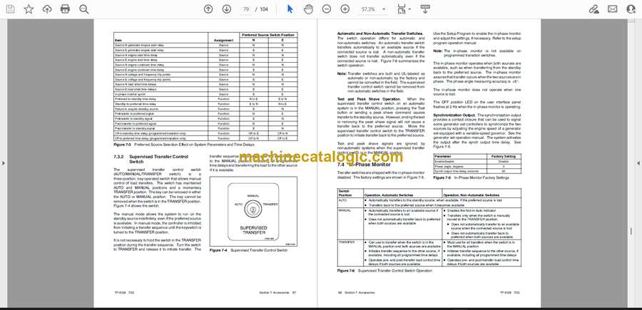
7.3.2 Supervised Transfer Control Switch . . . . . . . . . . . . . . . . . . . . . . . . . . . . . . 67
7.4 In-Phase Monitor . . . . . . . . . . . . . . . . . . . . . . . . . . . . . . . . . . . . . . . . . . . . . . . . . . . . . . 68
7.5 Programmable Inputs and Outputs . . . . . . . . . . . . . . . . . . . . . . . . . . . . . . . . . . . . . . 69
7.5.1 Programmable Input/Output (I/O) Modules . . . . . . . . . . . . . . . . . . . . . . . . 70
7.5.2 I/O Module Connection . . . . . . . . . . . . . . . . . . . . . . . . . . . . . . . . . . . . . . . . . 72
7.5.3 I/O Module Address . . . . . . . . . . . . . . . . . . . . . . . . . . . . . . . . . . . . . . . . . . . 72
7.5.4 I/O Module Faults and Diagnostics . . . . . . . . . . . . . . . . . . . . . . . . . . . . . . . 73
7.6 Load Shed (Forced Transfer to OFF) . . . . . . . . . . . . . . . . . . . . . . . . . . . . . . . . . . . . . 73
7.6.1 Description . . . . . . . . . . . . . . . . . . . . . . . . . . . . . . . . . . . . . . . . . . . . . . . . . . . 73
7.6.2 Connection . . . . . . . . . . . . . . . . . . . . . . . . . . . . . . . . . . . . . . . . . . . . . . . . . . . 73
7.7 Battery Charger . . . . . . . . . . . . . . . . . . . . . . . . . . . . . . . . . . . . . . . . . . . . . . . . . . . . . . . 74
7.7.1 Battery Charger Connection . . . . . . . . . . . . . . . . . . . . . . . . . . . . . . . . . . . . 75
7.7.2 Battery Charger Operation . . . . . . . . . . . . . . . . . . . . . . . . . . . . . . . . . . . . . . 77
7.7.3 Battery Charger Troubleshooting . . . . . . . . . . . . . . . . . . . . . . . . . . . . . . . . 79
7.7.4 Battery Charger Specifications . . . . . . . . . . . . . . . . . . . . . . . . . . . . . . . . . . 79
Appendix A Abbreviations . . . . . . . . . . . . . . . . . . . . . . . . . . . . . . . . . . . . . . . . . . . . . . . . . . . . . . . . . . . . . . . . . . A-1
Appendix B Specifications . . . . . . . . . . . . . . . . . . . . . . . . . . . . . . . . . . . . . . . . . . . . . . . . . . . . . . . . . . . . . . . . . . A-3


