Format: PDF (Printable Document)
File Language: English
File Pages: 44
File Size: 0.89 MB (Speed Download Link)
Brand: Kohler
Model: KSE TS 870 Automatic Transfer Switches Operation, Installation,
Book No: tp6295
Type of Document: Service Manual
$ 40
On a site where this Kohler KSE TS 870 is managing power between utility and a generator, this manual is what I’d keep on the bench to keep the switch operating safely and reliably. It helps you trace why the switch didn’t transfer during an outage, verify control signals, and confirm the mechanism is actually at fault before you start swapping parts. For example, if the generator is running but the load never picks up, I’d use this document to walk through the logic checks, mechanical inspections, and adjustment points in order, instead of guessing.
Applications & Use Cases
FAQ
Q: Can I keep this manual on a tablet in the field?
A: Yes, it’s practical to use digitally so you can zoom in on diagrams and search terms while working in the switchgear room.
Q: Should I print the whole manual or just parts of it?
A: Most techs print the key procedures and wiring info they use often, then keep the full manual digital for occasional reference.
Safety Note
Always de-energize and lock out all power sources before opening, testing, or servicing the transfer switch.
Product Identification Information . . . . . . . . . . . . . . . . . . . . . . . . . . . . . . . . . . . . . . . . . . . . . . . . . . . . . . . . . . . . 2
Safety Precautions and Instructions . . . . . . . . . . . . . . . . . . . . . . . . . . . . . . . . . . . . . . . . . . . . . . . . . . . . . . . . 5
Introduction . . . . . . . . . . . . . . . . . . . . . . . . . . . . . . . . . . . . . . . . . . . . . . . . . . . . . . . . . . . . . . . . . . . . . . . . . . . . . . . 7
List of Related Materials . . . . . . . . . . . . . . . . . . . . . . . . . . . . . . . . . . . . . . . . . . . . . . . . . . . . . 7
Service Assistance . . . . . . . . . . . . . . . . . . . . . . . . . . . . . . . . . . . . . . . . . . . . . . . . . . . . . . . . . . . . . . . . . . . . . . . . 8
Section 1 Installation . . . . . . . . . . . . . . . . . . . . . . . . . . . . . . . . . . . . . . . . . . . . . . . . . . . . . . . . . . . . . . . . . . . . . . 9
1.1 General Description . . . . . . . . . . . . . . . . . . . . . . . . . . . . . . . . . . . . . . . . . . . . . . . . . . . 9
1.2 Environmental Conditions . . . . . . . . . . . . . . . . . . . . . . . . . . . . . . . . . . . . . . . . . . . . . . 9
1.2.1 Equipment Storage . . . . . . . . . . . . . . . . . . . . . . . . . . . . . . . . . . . . . . . . . . . . 9
1.2.2 Equipment Operation . . . . . . . . . . . . . . . . . . . . . . . . . . . . . . . . . . . . . . . . . . 9
1.3 Product Code . . . . . . . . . . . . . . . . . . . . . . . . . . . . . . . . . . . . . . . . . . . . . . . . . . . . . . . . . 10
1.4 Dimensions . . . . . . . . . . . . . . . . . . . . . . . . . . . . . . . . . . . . . . . . . . . . . . . . . . . . . . . . . . 10
1.5 Installer Notes . . . . . . . . . . . . . . . . . . . . . . . . . . . . . . . . . . . . . . . . . . . . . . . . . . . . . . . . 11
1.6 Dielectric Testing . . . . . . . . . . . . . . . . . . . . . . . . . . . . . . . . . . . . . . . . . . . . . . . . . . . . . . 11
1.7 Electrical Connections/Cable Terminal Information . . . . . . . . . . . . . . . . . . . . . . . . . 11
1.8 Upstream Circuit Protective Devices . . . . . . . . . . . . . . . . . . . . . . . . . . . . . . . . . . . . . 12
1.8.1 Transfer Switches with Integral Overcurrent Protection . . . . . . . . . . . . . 12
1.8.2 Overcurrent Protection . . . . . . . . . . . . . . . . . . . . . . . . . . . . . . . . . . . . . . . . . 12
1.8.3 Requirements for Upstream Circuit Protective Devices . . . . . . . . . . . . . 13
1.9 Transfer Switches with Multi-Tap Voltage Capability . . . . . . . . . . . . . . . . . . . . . . . . 14
1.10 System Phasing, High Leg Delta Systems . . . . . . . . . . . . . . . . . . . . . . . . . . . . . . . . 14
1.11 Remote Start Contact Field Wiring . . . . . . . . . . . . . . . . . . . . . . . . . . . . . . . . . . . . . . . 15
1.12 Installation of Open Type Transfer Switches . . . . . . . . . . . . . . . . . . . . . . . . . . . . . . 15
1.13 Typical Commissioning Procedures . . . . . . . . . . . . . . . . . . . . . . . . . . . . . . . . . . . . . . 15
1.14 Ground Fault Site Test Requirements . . . . . . . . . . . . . . . . . . . . . . . . . . . . . . . . . . . . 16
Section 2 Operation . . . . . . . . . . . . . . . . . . . . . . . . . . . . . . . . . . . . . . . . . . . . . . . . . . . . . . . . . . . . . . . . . . . . . . . 17
2.1 Standard Automatic Transfer Switch Normal Operation . . . . . . . . . . . . . . . . . . . . . 17
2.2 Service Entrance Automatic Transfer Switch . . . . . . . . . . . . . . . . . . . . . . . . . . . . . . 17
2.2.1 Normal Operation . . . . . . . . . . . . . . . . . . . . . . . . . . . . . . . . . . . . . . . . . . . . . 17
2.2.2 Overcurrent Trip . . . . . . . . . . . . . . . . . . . . . . . . . . . . . . . . . . . . . . . . . . . . . . . 17
2.2.3 Service Disconnect Procedure . . . . . . . . . . . . . . . . . . . . . . . . . . . . . . . . . . 17
2.2.4 Additional Procedures . . . . . . . . . . . . . . . . . . . . . . . . . . . . . . . . . . . . . . . . . 18
2.3 Test Modes . . . . . . . . . . . . . . . . . . . . . . . . . . . . . . . . . . . . . . . . . . . . . . . . . . . . . . . . . . . 19
Section 3 Servicing Transfer Switch Mechanisms . . . . . . . . . . . . . . . . . . . . . . . . . . . . . . . . . . . . . . . . . . . . 21
3.1 Equipment Inspection . . . . . . . . . . . . . . . . . . . . . . . . . . . . . . . . . . . . . . . . . . . . . . . . . . 21
3.2 Transfer Mechanism, 100–800 Amp S-Style . . . . . . . . . . . . . . . . . . . . . . . . . . . . . . . 22
3.2.1 Description . . . . . . . . . . . . . . . . . . . . . . . . . . . . . . . . . . . . . . . . . . . . . . . . . . . 22
3.2.2 Manual Operation . . . . . . . . . . . . . . . . . . . . . . . . . . . . . . . . . . . . . . . . . . . . . 22
3.3 Transfer Mechanism, 1000–1200 Amp T-Style . . . . . . . . . . . . . . . . . . . . . . . . . . . . . 23
3.3.1 General Description . . . . . . . . . . . . . . . . . . . . . . . . . . . . . . . . . . . . . . . . . . . 23
3.3.2 Manual Operation . . . . . . . . . . . . . . . . . . . . . . . . . . . . . . . . . . . . . . . . . . . . . 23
3.3.3 Recommended Maintenance . . . . . . . . . . . . . . . . . . . . . . . . . . . . . . . . . . . . 24
Section 4 Transfer Mechanism Drawings . . . . . . . . . . . . . . . . . . . . . . . . . . . . . . . . . . . . . . . . . . . . . . . . . . . . 25
4.1 100–250 Amp S-Style Transfer Mechanism . . . . . . . . . . . . . . . . . . . . . . . . . . . . . . . 25
4.2 400–800 Amp S-Style Transfer Mechanism . . . . . . . . . . . . . . . . . . . . . . . . . . . . . . . 26
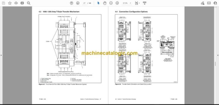
4.3 1000–1200 Amp T-Style Transfer Mechanism . . . . . . . . . . . . . . . . . . . . . . . . . . . . . 27
4.4 Connection Configuration Options . . . . . . . . . . . . . . . . . . . . . . . . . . . . . . . . . . . . . . . 28
Section 5 Troubleshooting . . . . . . . . . . . . . . . . . . . . . . . . . . . . . . . . . . . . . . . . . . . . . . . . . . . . . . . . . . . . . . . . . 29
Table of Contents, continued
4 Table of Contents TP-6295 2/09
Section 6 Service Parts . . . . . . . . . . . . . . . . . . . . . . . . . . . . . . . . . . . . . . . . . . . . . . . . . . . . . . . . . . . . . . . . . . . . 31
Section 7 Performance Test Form . . . . . . . . . . . . . . . . . . . . . . . . . . . . . . . . . . . . . . . . . . . . . . . . . . . . . . . . . . 33
Appendix A Abbreviations . . . . . . . . . . . . . . . . . . . . . . . . . . . . . . . . . . . . . . . . . . . . . . . . . . . . . . . . . . . . . . . . . . 35
Appendix B Commissioning Procedures . . . . . . . . . . . . . . . . . . . . . . . . . . . . . . . . . . . . . . . . . . . . . . . . . . . . . . 37
Appendix C Changing System Voltage . . . . . . . . . . . . . . . . . . . . . . . . . . . . . . . . . . . . . . . . . . . . . . . . . . . . . . . 40


