Format: PDF (Printable Document)
File Language: English
File Pages: 126
File Size: 2.67 MB (Speed Download Link)
Brand: Kohler
Model: KSS, KSP, KGS, KGP Automatic Transfer Switches
Book No: tp6461
Type of Document: Service Manual
$ 40
These Kohler automatic transfer switches sit between your utility feed and generator, usually in plant rooms, hospitals, data centers, or commercial buildings, and their whole job is to move the load cleanly when the power source changes. This service manual is what I use to trace control faults, verify timing and sensing logic, and walk through safe disassembly of the switching and control sections. For example, if a switch hangs in one position after a utility outage, this manual guides you step by step so you can confirm whether it’s a control board issue, a sensing problem, or a mechanical binding before you order any parts.
Applications & Use Cases
FAQ
Q: Can I keep this manual on a tablet at the switchgear room?
A: Yes, it’s practical to use digitally so you can zoom in on diagrams and follow tests right at the cabinet.
Q: Is it worth printing parts of it?
A: Many techs print the key procedures and schematics they use often, then keep them in a jobsite binder for quick access.
Safety Note
Always verify both sources are properly isolated and locked out before opening or working inside the transfer switch.
Safety Precautions and Instructions . . . . . . . . . . . . . . . . . . . . . . . . . . . . . . . . . . . . . . . . . . . . . . . . . . . . . . . . 7
Introduction . . . . . . . . . . . . . . . . . . . . . . . . . . . . . . . . . . . . . . . . . . . . . . . . . . . . . . . . . . . . . . . . . . . . . . . . . . . . . . . 11
List of Related Materials . . . . . . . . . . . . . . . . . . . . . . . . . . . . . . . . . . . . . . . . . . . . . . . . . . . . . 11
Service Assistance . . . . . . . . . . . . . . . . . . . . . . . . . . . . . . . . . . . . . . . . . . . . . . . . . . . . . . . . . . . . . . . . . . . . . . . . 12
Section 1 Scheduled Maintenance . . . . . . . . . . . . . . . . . . . . . . . . . . . . . . . . . . . . . . . . . . . . . . . . . . . . . . . . . . 13
1.1 Introduction . . . . . . . . . . . . . . . . . . . . . . . . . . . . . . . . . . . . . . . . . . . . . . . . . . . . . . . . . . 13
1.2 Inspection and Service . . . . . . . . . . . . . . . . . . . . . . . . . . . . . . . . . . . . . . . . . . . . . . . . . 14
1.2.1 General Inspection . . . . . . . . . . . . . . . . . . . . . . . . . . . . . . . . . . . . . . . . . . . . 14
1.2.2 Internal Inspections and Maintenance . . . . . . . . . . . . . . . . . . . . . . . . . . . . 15
1.3 Testing . . . . . . . . . . . . . . . . . . . . . . . . . . . . . . . . . . . . . . . . . . . . . . . . . . . . . . . . . . . . . . 16
1.3.1 Weekly Generator Set Exercise . . . . . . . . . . . . . . . . . . . . . . . . . . . . . . . . . 16
1.3.2 Monthly Automatic Operation Test . . . . . . . . . . . . . . . . . . . . . . . . . . . . . . . 16
1.3.3 Other Tests . . . . . . . . . . . . . . . . . . . . . . . . . . . . . . . . . . . . . . . . . . . . . . . . . . . 16
1.4 Service Schedule . . . . . . . . . . . . . . . . . . . . . . . . . . . . . . . . . . . . . . . . . . . . . . . . . . . . . 18
1.5 View Maintenance Records . . . . . . . . . . . . . . . . . . . . . . . . . . . . . . . . . . . . . . . . . . . . . 20
1.6 Reset Data . . . . . . . . . . . . . . . . . . . . . . . . . . . . . . . . . . . . . . . . . . . . . . . . . . . . . . . . . . . 20
1.6.1 Reset Maintenance Records . . . . . . . . . . . . . . . . . . . . . . . . . . . . . . . . . . . . 20
1.6.2 Reset Event History . . . . . . . . . . . . . . . . . . . . . . . . . . . . . . . . . . . . . . . . . . . 20
1.6.3 Reset Default Parameters . . . . . . . . . . . . . . . . . . . . . . . . . . . . . . . . . . . . . . 20
1.6.4 Reset and Disable Test Password . . . . . . . . . . . . . . . . . . . . . . . . . . . . . . . 20
1.6.5 File Maintenance . . . . . . . . . . . . . . . . . . . . . . . . . . . . . . . . . . . . . . . . . . . . . . 20
1.6.6 Reset Data Procedure . . . . . . . . . . . . . . . . . . . . . . . . . . . . . . . . . . . . . . . . . 21
Section 2 Controller Troubleshooting . . . . . . . . . . . . . . . . . . . . . . . . . . . . . . . . . . . . . . . . . . . . . . . . . . . . . . . 23
2.1 Initial Checks . . . . . . . . . . . . . . . . . . . . . . . . . . . . . . . . . . . . . . . . . . . . . . . . . . . . . . . . . 23
2.2 Controller Backup Battery . . . . . . . . . . . . . . . . . . . . . . . . . . . . . . . . . . . . . . . . . . . . . . 24
2.3 View Event History . . . . . . . . . . . . . . . . . . . . . . . . . . . . . . . . . . . . . . . . . . . . . . . . . . . . 24
2.4 System Settings . . . . . . . . . . . . . . . . . . . . . . . . . . . . . . . . . . . . . . . . . . . . . . . . . . . . . . 26
2.4.1 Controller Source Settings . . . . . . . . . . . . . . . . . . . . . . . . . . . . . . . . . . . . . . 26
2.4.2 Voltage and Frequency Pickup and Dropout Settings . . . . . . . . . . . . . . . 26
2.5 Time Delays . . . . . . . . . . . . . . . . . . . . . . . . . . . . . . . . . . . . . . . . . . . . . . . . . . . . . . . . . . 27
2.6 Common Alarms . . . . . . . . . . . . . . . . . . . . . . . . . . . . . . . . . . . . . . . . . . . . . . . . . . . . . . 28
2.7 Warnings and Faults . . . . . . . . . . . . . . . . . . . . . . . . . . . . . . . . . . . . . . . . . . . . . . . . . . . 29
2.7.1 Fault Reset . . . . . . . . . . . . . . . . . . . . . . . . . . . . . . . . . . . . . . . . . . . . . . . . . . . 30
2.7.2 Module Status Change . . . . . . . . . . . . . . . . . . . . . . . . . . . . . . . . . . . . . . . . . 30
2.7.3 Module Status Conflict . . . . . . . . . . . . . . . . . . . . . . . . . . . . . . . . . . . . . . . . . 31
2.8 Events and Faults . . . . . . . . . . . . . . . . . . . . . . . . . . . . . . . . . . . . . . . . . . . . . . . . . . . . . 32
2.9 Controller Troubleshooting Table . . . . . . . . . . . . . . . . . . . . . . . . . . . . . . . . . . . . . . . . 35
Section 3 Transfer Switch Troubleshooting . . . . . . . . . . . . . . . . . . . . . . . . . . . . . . . . . . . . . . . . . . . . . . . . . 37
3.1 Initial Checks . . . . . . . . . . . . . . . . . . . . . . . . . . . . . . . . . . . . . . . . . . . . . . . . . . . . . . . . . 37
3.2 Transfer Switch Troubleshooting Table . . . . . . . . . . . . . . . . . . . . . . . . . . . . . . . . . . . 37
3.3 System Power . . . . . . . . . . . . . . . . . . . . . . . . . . . . . . . . . . . . . . . . . . . . . . . . . . . . . . . . 41
3.3.1 Verify Power to the ATS . . . . . . . . . . . . . . . . . . . . . . . . . . . . . . . . . . . . . . . . 41
3.3.2 Source Voltage, Frequency, and Phase Rotation Checks . . . . . . . . . . . 41
3.4 Contacts . . . . . . . . . . . . . . . . . . . . . . . . . . . . . . . . . . . . . . . . . . . . . . . . . . . . . . . . . . . . . 42
3.5 Rectifier Test . . . . . . . . . . . . . . . . . . . . . . . . . . . . . . . . . . . . . . . . . . . . . . . . . . . . . . . . . 43
3.6 Solenoid Tests . . . . . . . . . . . . . . . . . . . . . . . . . . . . . . . . . . . . . . . . . . . . . . . . . . . . . . . . 43
3.6.1 Solenoid Coil Resistance . . . . . . . . . . . . . . . . . . . . . . . . . . . . . . . . . . . . . . . 43
3.6.2 Solenoid Operation . . . . . . . . . . . . . . . . . . . . . . . . . . . . . . . . . . . . . . . . . . . . 44
3.6.3 Solenoid Operation Diagrams, 40–225 Amp Model KSS Open Transition
Switches . . . . . . . . . . . . . . . . . . . . . . . . . . . . . . . . . . . . . . . . . . . . . . . . . . . . . 45
3.6.4 Solenoid Operation Diagrams, 400–600 Amp Model KSS Open Transition
Switches . . . . . . . . . . . . . . . . . . . . . . . . . . . . . . . . . . . . . . . . . . . . . . . . . . . . . 46
Table of Contents, continued
Table of Contents TP-6461 1/08
3.6.5 Solenoid Operation Diagrams, Model KSP Programmed-Transition Models
47
3.6.6 Solenoid Operation Diagrams, Model KGS Open Transition
Bypass/Isolation Switches . . . . . . . . . . . . . . . . . . . . . . . . . . . . . . . . . . . . . . 49
3.6.7 Solenoid Operation Diagrams, 150–400 Amp Model KGP
Programmed-Transition Bypass/Isolation Switches . . . . . . . . . . . . . . . . . 50
Solenoid Operation Diagrams, 150–400 Amp Model KGP
Programmed-Transition Bypass/Isolation Switches, continued . . . . . . . 51
3.6.8 Solenoid Operation Diagrams, 600–3000 Amp Model KGP
Programmed-Transition Bypass/Isolation Switches . . . . . . . . . . . . . . . . . 52
Solenoid Operation Diagrams, 600–3000 Amp Model KGP
Programmed-Transition Bypass/Isolation Switches, Continued . . . . . . 53
Section 4 Controller Test and Replacement . . . . . . . . . . . . . . . . . . . . . . . . . . . . . . . . . . . . . . . . . . . . . . . . . 55
4.1 User Interface Panel . . . . . . . . . . . . . . . . . . . . . . . . . . . . . . . . . . . . . . . . . . . . . . . . . . . 55
4.1.1 Display . . . . . . . . . . . . . . . . . . . . . . . . . . . . . . . . . . . . . . . . . . . . . . . . . . . . . . 55
4.1.2 LED Indicators . . . . . . . . . . . . . . . . . . . . . . . . . . . . . . . . . . . . . . . . . . . . . . . . 55
4.1.3 Lamp Test . . . . . . . . . . . . . . . . . . . . . . . . . . . . . . . . . . . . . . . . . . . . . . . . . . . . 56
4.1.4 Pushbuttons . . . . . . . . . . . . . . . . . . . . . . . . . . . . . . . . . . . . . . . . . . . . . . . . . . 56
4.2 Controller Circuit Boards and Connectors . . . . . . . . . . . . . . . . . . . . . . . . . . . . . . . . . 57
4.3 Controller Power . . . . . . . . . . . . . . . . . . . . . . . . . . . . . . . . . . . . . . . . . . . . . . . . . . . . . . 58
4.3.1 Controller Power Supply . . . . . . . . . . . . . . . . . . . . . . . . . . . . . . . . . . . . . . . . 58
4.3.2 Controller Backup Battery . . . . . . . . . . . . . . . . . . . . . . . . . . . . . . . . . . . . . . 59
4.3.3 Powering the Controller Directly (Service Kit GM52407) . . . . . . . . . . . . 59
4.4 Sequence of Operation . . . . . . . . . . . . . . . . . . . . . . . . . . . . . . . . . . . . . . . . . . . . . . . . 60
4.4.1 Controller Powerup Reset Sequence of Operation . . . . . . . . . . . . . . . . . 60
4.4.2 Preferred Source Loss and Return . . . . . . . . . . . . . . . . . . . . . . . . . . . . . . . 60
4.5 System Test . . . . . . . . . . . . . . . . . . . . . . . . . . . . . . . . . . . . . . . . . . . . . . . . . . . . . . . . . . 61
4.5.1 Unloaded System Test . . . . . . . . . . . . . . . . . . . . . . . . . . . . . . . . . . . . . . . . . 61
4.5.2 Loaded System Test . . . . . . . . . . . . . . . . . . . . . . . . . . . . . . . . . . . . . . . . . . . 61
4.5.3 Auto-Loaded System Test . . . . . . . . . . . . . . . . . . . . . . . . . . . . . . . . . . . . . . 61
4.5.4 Test Procedure . . . . . . . . . . . . . . . . . . . . . . . . . . . . . . . . . . . . . . . . . . . . . . . . 61
4.5.5 Test Sequence of Operation . . . . . . . . . . . . . . . . . . . . . . . . . . . . . . . . . . . . 64
4.6 Exercise . . . . . . . . . . . . . . . . . . . . . . . . . . . . . . . . . . . . . . . . . . . . . . . . . . . . . . . . . . . . . 66
4.6.1 Exerciser Sequence of Operation . . . . . . . . . . . . . . . . . . . . . . . . . . . . . . . . 66
4.7 Engine Start . . . . . . . . . . . . . . . . . . . . . . . . . . . . . . . . . . . . . . . . . . . . . . . . . . . . . . . . . . 68
4.8 Controller DIP Switches . . . . . . . . . . . . . . . . . . . . . . . . . . . . . . . . . . . . . . . . . . . . . . . . 69
4.9 Calibration . . . . . . . . . . . . . . . . . . . . . . . . . . . . . . . . . . . . . . . . . . . . . . . . . . . . . . . . . . . 70
4.10 Position Microswitch Test . . . . . . . . . . . . . . . . . . . . . . . . . . . . . . . . . . . . . . . . . . . . . . . 71
4.11 Programmed-Transition Interface Board . . . . . . . . . . . . . . . . . . . . . . . . . . . . . . . . . . 71
4.12 File Transfer through the USB Port . . . . . . . . . . . . . . . . . . . . . . . . . . . . . . . . . . . . . . 72
4.12.1 Configuration files . . . . . . . . . . . . . . . . . . . . . . . . . . . . . . . . . . . . . . . . . . . . . 72
4.12.2 File Transfer . . . . . . . . . . . . . . . . . . . . . . . . . . . . . . . . . . . . . . . . . . . . . . . . . . 73
4.13 Controller Application Program . . . . . . . . . . . . . . . . . . . . . . . . . . . . . . . . . . . . . . . . . . 73
4.14 Controller Replacement . . . . . . . . . . . . . . . . . . . . . . . . . . . . . . . . . . . . . . . . . . . . . . . . 74
4.14.1 Controller Configuration (Settings) . . . . . . . . . . . . . . . . . . . . . . . . . . . . . . . 74
4.14.2 [Circuit Board and Electronic Component Handling] . . . . . . . . . . . . . . . . 74
4.14.3 Replacement Procedure . . . . . . . . . . . . . . . . . . . . . . . . . . . . . . . . . . . . . . . . 75
Section 5 Component Replacement, Model KGS/KGP . . . . . . . . . . . . . . . . . . . . . . . . . . . . . . . . . . . . . . . . 79
5.1 Introduction . . . . . . . . . . . . . . . . . . . . . . . . . . . . . . . . . . . . . . . . . . . . . . . . . . . . . . . . . . 79
5.2 Contact Assembly Removal and Replacement . . . . . . . . . . . . . . . . . . . . . . . . . . . . 79
5.2.1 800–1200 Amp Models . . . . . . . . . . . . . . . . . . . . . . . . . . . . . . . . . . . . . . . . . 79
5.2.2 1600–2000 Amp Models . . . . . . . . . . . . . . . . . . . . . . . . . . . . . . . . . . . . . . . 81
5.2.3 3000 Amp Model . . . . . . . . . . . . . . . . . . . . . . . . . . . . . . . . . . . . . . . . . . . . . . 83
5.3 Auxiliary Switch Removal and Replacement . . . . . . . . . . . . . . . . . . . . . . . . . . . . . . 85
Section 6 Component Replacement, Model KSS . . . . . . . . . . . . . . . . . . . . . . . . . . . . . . . . . . . . . . . . . . . . . 87
6.1 Introduction . . . . . . . . . . . . . . . . . . . . . . . . . . . . . . . . . . . . . . . . . . . . . . . . . . . . . . . . . . 87
6.2 Microswitch Replacement . . . . . . . . . . . . . . . . . . . . . . . . . . . . . . . . . . . . . . . . . . . . . . 88
6.2.1 40–260 Amp . . . . . . . . . . . . . . . . . . . . . . . . . . . . . . . . . . . . . . . . . . . . . . . . . . 88
6.2.2 400–600 Amp . . . . . . . . . . . . . . . . . . . . . . . . . . . . . . . . . . . . . . . . . . . . . . . . . 89
6.3 Power Panel Replacement . . . . . . . . . . . . . . . . . . . . . . . . . . . . . . . . . . . . . . . . . . . . . 90
6.4 Arc Chute Replacement . . . . . . . . . . . . . . . . . . . . . . . . . . . . . . . . . . . . . . . . . . . . . . . . 91
6.5 Limit Switch Assembly Replacement . . . . . . . . . . . . . . . . . . . . . . . . . . . . . . . . . . . . . 92
6.6 Solenoid and Rectifier Replacement . . . . . . . . . . . . . . . . . . . . . . . . . . . . . . . . . . . . . 94
6.6.1 Solenoid and Rectifier Replacement, 40–225 Amp Models . . . . . . . . . . 94
6.6.2 Solenoid and Rectifier Replacement, 400–600 Amp Models . . . . . . . . . 96
Section 7 Component Replacement, Model KSP . . . . . . . . . . . . . . . . . . . . . . . . . . . . . . . . . . . . . . . . . . . . . 101
7.1 Introduction . . . . . . . . . . . . . . . . . . . . . . . . . . . . . . . . . . . . . . . . . . . . . . . . . . . . . . . . . . 101
7.2 Component Replacement, 100–400 Amp Models . . . . . . . . . . . . . . . . . . . . . . . . . . 101
7.2.1 Disassembly, 100–400 Amps . . . . . . . . . . . . . . . . . . . . . . . . . . . . . . . . . . . 101
7.2.2 Reassembly, 100–400 Amps . . . . . . . . . . . . . . . . . . . . . . . . . . . . . . . . . . . . 102
7.2.3 Printed Circuit Board Replacement, 100–400 Amps . . . . . . . . . . . . . . . . 104
7.2.4 Closing Coil Replacement, 100–400 Amps . . . . . . . . . . . . . . . . . . . . . . . . 105
7.2.5 Select Coil Replacement, 100–400 Amps . . . . . . . . . . . . . . . . . . . . . . . . . 105
7.2.6 Trip Coil Replacement, 100–400 Amps . . . . . . . . . . . . . . . . . . . . . . . . . . . 106
7.2.7 Arc Chute Replacement, 100–400 Amps . . . . . . . . . . . . . . . . . . . . . . . . . . 108
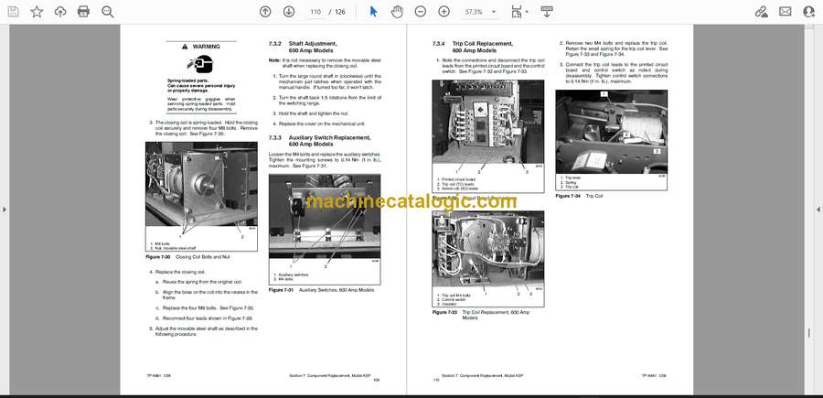
7.3 Component Replacement, 600 Amp Models . . . . . . . . . . . . . . . . . . . . . . . . . . . . . . 108
7.3.1 Closing Coil Replacement, 600 Amp Models . . . . . . . . . . . . . . . . . . . . . . 108
7.3.2 Shaft Adjustment, 600 Amp Models . . . . . . . . . . . . . . . . . . . . . . . . . . . . . . 109
7.3.3 Auxiliary Switch Replacement, 600 Amp Models . . . . . . . . . . . . . . . . . . . 109
7.3.4 Trip Coil Replacement, 600 Amp Models . . . . . . . . . . . . . . . . . . . . . . . . . 110
7.3.5 Select Coil Replacement, 600 Amp Models . . . . . . . . . . . . . . . . . . . . . . . 111
7.3.6 Printed Circuit Board Replacement, 600 Amp Models . . . . . . . . . . . . . . 111
7.3.7 Arc Chute Replacement, 600 Amp Models . . . . . . . . . . . . . . . . . . . . . . . . 111
Appendix A Abbreviations . . . . . . . . . . . . . . . . . . . . . . . . . . . . . . . . . . . . . . . . . . . . . . . . . . . . . . . . . . . . . . . . . . 113
Appendix B Screen Summaries . . . . . . . . . . . . . . . . . . . . . . . . . . . . . . . . . . . . . . . . . . . . . . . . . . . . . . . . . . . . . 115
Appendix C Noise and Wiring Practices . . . . . . . . . . . . . . . . . . . . . . . . . . . . . . . . . . . . . . . . . . . . . . . . . . . . . . 118
Appendix D Common Hardware Application Guidelines . . . . . . . . . . . . . . . . . . . . . . . . . . . . . . . . . . . . . . . . 119
Appendix E General Torque Specifications . . . . . . . . . . . . . . . . . . . . . . . . . . . . . . . . . . . . . . . . . . . . . . . . . . . 120
Appendix F Common Hardware Identification . . . . . . . . . . . . . . . . . . . . . . . . . . . . . . . . . . . . . . . . . . . . . . . . . 121
Appendix G Common Hardware List . . . . . . . . . . . . . . . . . . . . . . . . . . . . . . . . . . . . . . . . . . . . . . . . . . . . . . . . . 122


