Format: PDF (Printable Document)
File Language: English
File Pages: 103
File Size: 1.96 MB (Speed Download Link)
Brand: Kohler
Model: PM340
Book No: tp5875
Type of Document: Operation and Installation Manual
$ 40
The Kohler PM340 is a standby/backup power unit typically parked beside buildings, in plant rooms, or near job trailers to keep lights, pumps, or small systems running when utility power drops. This Operation and Installation Manual is what I’d keep on hand when mounting the unit, tying it into the electrical system, and then proving it will start and carry load reliably. If the set is cranking but not picking up the building, or the LEDs on the panel aren’t behaving as expected, this is the book I’d use to trace the installation, verify wiring, and confirm it’s been set up the way Kohler intended.
Applications & Use Cases
FAQ
Q: Is this manual useful to keep as a PDF on a tablet or phone at the jobsite?
A: Yes, it’s handy to zoom in on diagrams, search terms, and carry it around the building without risking a greasy paper copy.
Q: Should I still print this manual if I already have it digitally?
A: I recommend printing at least the key installation and operation pages so you can mark them up, tape them near the unit, and keep working even if your device battery dies.
Safety Note
Always lock out power sources and follow the manual’s precautions before working on or near the PM340.
Safety Precautions and Instructions
Introduction
List of Related Materials
Service Assistance
Section Features and Specifications
Features
Local LED Indicators
Digital Display and Keypad
Internal Components
Fuses
Terminal Strips
Specifications
Section Operation
Startup
Prestart Checklist
Powerup Messages
Setting the Time and Date
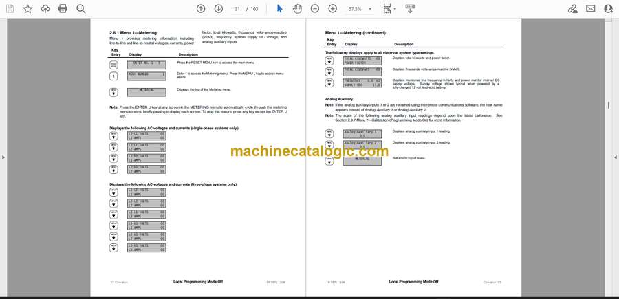
Checking Meter Readings
Local LED Indicators
System Ready
Test Mode Active
Programming Mode
Display Warnings
Digital Display and Keypad
Keypad
Display Messages
Monitoring and Programming Setup
Programming Mode
Remote Control
Local Single Connection
Local Area Network
Remote Single Connection
Remote Area Network
Relay Outputs and Contact Inputs
Auxiliary Warning
ATS Contact Position
ATS Status and Test Mode
Menu List Summary
Local Programming Mode Off
Menu Metering
Menu ATS Status
Menu Time and Date
Menu System Settings
Menu User-Defined Functions
Menu System History
Menu Calibration
Menu Remote Control
Menu Programming Mode
Section Scheduled Maintenance
General
Service Schedule
Section Troubleshooting
General
Troubleshooting Chart
Section Accessories
Accessory Locations
Accessory Kits
AC Power Supply
Ten-Relay Dry Contact Circuit Board
Communications Accessories
RS-232 Communications Module
RS-485 Communications Module
Internal RS-232 to RS-485 Converter
External Modem
Section Diagrams and Drawings
Section Installation
Upon Receipt of Unit
Inspection
Unpacking
Storage
Mounting
Electrical Wiring
AC Sensing Connections
DC Power Connections
DC Control Connections
Accessory and Customer Wiring
Initial Startup and Setup
Starting Unit for the First Time
Programming System Settings
Calibrating Unit
Programming Other Settings and Testing
Terminal Strip Identification
Appendix Glossary of Abbreviations


