Format: PDF (Printable Document)
File Language: English
File Pages: 72
File Size: 3.93 MB (Speed Download Link)
Brand: Kohler
Model: RSB, ATSR Intelligent Transfer Switch Conversion Kit Automatic Transfer Switches
Book No: tp6486
Type of Document: Installation Manual
$ 40
When you’re dealing with a Kohler automatic transfer switch on a building or facility that needs clean, reliable backup power, this installation manual is what you use to properly fit and convert the RSB or ATSR Intelligent Transfer Switch Conversion Kit. It walks you through how to mount, wire, and set up the kit so the switch reliably moves the load between utility and generator. If, for example, the transfer switch is failing to transfer automatically after a retrofit, this is the document I’d pull out to trace the wiring changes and verify the conversion was done correctly.
Applications & Use Cases
FAQ
Q: Can I keep this manual on a tablet in the field?
A: Yes, it’s practical to use digitally so you can zoom in on diagrams and search text while standing at the switchboard.
Q: Should I print this or is digital enough for installation work?
A: Many techs print the key wiring and layout pages to mark notes, then keep the full manual digital for quick reference.
Safety Note
Always isolate all power sources, lock out/tag out, and verify zero voltage before opening or working inside any transfer switch.
Product Identification Information . . . . . . . . . . . . . . . . . . . . . . . . . . . . . . . . . . . . . . . . . . . . . . . . . . . . . . . . . . 2
Safety Precautions and Instructions . . . . . . . . . . . . . . . . . . . . . . . . . . . . . . . . . . . . . . . . . . . . . . . . . . . . . . . . 5
Introduction . . . . . . . . . . . . . . . . . . . . . . . . . . . . . . . . . . . . . . . . . . . . . . . . . . . . . . . . . . . . . . . . . . . . . . . . . . . . . . . 7
Service Assistance . . . . . . . . . . . . . . . . . . . . . . . . . . . . . . . . . . . . . . . . . . . . . . . . . . . . . . . . . . . . . . . . . . . . . . . . 10
Section 1 Specifications . . . . . . . . . . . . . . . . . . . . . . . . . . . . . . . . . . . . . . . . . . . . . . . . . . . . . . . . . . . . . . . . . . . 11
Section 2 Conversion Kit Installation . . . . . . . . . . . . . . . . . . . . . . . . . . . . . . . . . . . . . . . . . . . . . . . . . . . . . . . 13
2.1 Load Center Installation . . . . . . . . . . . . . . . . . . . . . . . . . . . . . . . . . . . . . . . . . . . . . . . . 13
2.2 Receipt of Unit . . . . . . . . . . . . . . . . . . . . . . . . . . . . . . . . . . . . . . . . . . . . . . . . . . . . . . . . 13
2.2.1 Inspection . . . . . . . . . . . . . . . . . . . . . . . . . . . . . . . . . . . . . . . . . . . . . . . . . . . . 13
2.2.2 Storage . . . . . . . . . . . . . . . . . . . . . . . . . . . . . . . . . . . . . . . . . . . . . . . . . . . . . . 13
2.2.3 Lifting . . . . . . . . . . . . . . . . . . . . . . . . . . . . . . . . . . . . . . . . . . . . . . . . . . . . . . . . 13
2.2.4 Unpacking . . . . . . . . . . . . . . . . . . . . . . . . . . . . . . . . . . . . . . . . . . . . . . . . . . . . 13
2.3 Working Procedures . . . . . . . . . . . . . . . . . . . . . . . . . . . . . . . . . . . . . . . . . . . . . . . . . . . 14
2.4 Preliminary Recommendations . . . . . . . . . . . . . . . . . . . . . . . . . . . . . . . . . . . . . . . . . . 14
2.4.1 Tools Required . . . . . . . . . . . . . . . . . . . . . . . . . . . . . . . . . . . . . . . . . . . . . . . . 15
2.4.2 Qualified Personnel . . . . . . . . . . . . . . . . . . . . . . . . . . . . . . . . . . . . . . . . . . . . 15
2.4.3 Wiring Notes . . . . . . . . . . . . . . . . . . . . . . . . . . . . . . . . . . . . . . . . . . . . . . . . . . 15
2.4.4 Grounding Note . . . . . . . . . . . . . . . . . . . . . . . . . . . . . . . . . . . . . . . . . . . . . . . 16
2.4.5 Enclosure Type Note . . . . . . . . . . . . . . . . . . . . . . . . . . . . . . . . . . . . . . . . . . 16
2.4.6 Power Removal . . . . . . . . . . . . . . . . . . . . . . . . . . . . . . . . . . . . . . . . . . . . . . . 17
2.5 Removing Cover . . . . . . . . . . . . . . . . . . . . . . . . . . . . . . . . . . . . . . . . . . . . . . . . . . . . . . 17
2.6 Inspecting Load Center Interior Assembly . . . . . . . . . . . . . . . . . . . . . . . . . . . . . . . . 17
2.7 Installing Main Circuit Breaker . . . . . . . . . . . . . . . . . . . . . . . . . . . . . . . . . . . . . . . . . . 18
2.8 Installing Generator Circuit Breaker . . . . . . . . . . . . . . . . . . . . . . . . . . . . . . . . . . . . . . 19
2.9 Installing Wireway Brackets . . . . . . . . . . . . . . . . . . . . . . . . . . . . . . . . . . . . . . . . . . . . 19
2.10 Installing Fuse Holders . . . . . . . . . . . . . . . . . . . . . . . . . . . . . . . . . . . . . . . . . . . . . . . . . 20
2.10.1 Preparing Fuse Holders . . . . . . . . . . . . . . . . . . . . . . . . . . . . . . . . . . . . . . . . 20
2.10.2 Mounting Fuse Holders . . . . . . . . . . . . . . . . . . . . . . . . . . . . . . . . . . . . . . . . 20
2.11 Installing Generator Terminal Block . . . . . . . . . . . . . . . . . . . . . . . . . . . . . . . . . . . . . . 22
2.12 Installing Automatic Transfer Mechanism . . . . . . . . . . . . . . . . . . . . . . . . . . . . . . . . . 23
2.13 Connecting Control Harness 9-Pin Plugs . . . . . . . . . . . . . . . . . . . . . . . . . . . . . . . . . 24
2.14 Installing Utility Control Tap Connections . . . . . . . . . . . . . . . . . . . . . . . . . . . . . . . . . 25
2.15 Terminating Line Conductors . . . . . . . . . . . . . . . . . . . . . . . . . . . . . . . . . . . . . . . . . . . . 25
2.16 Connecting Optional Accessory Board . . . . . . . . . . . . . . . . . . . . . . . . . . . . . . . . . . . 26
2.16.1 Accessory Board Input and Output Connections . . . . . . . . . . . . . . . . . . . 26
2.16.2 Accessory Board Time Delay Adjustment Switches . . . . . . . . . . . . . . . . 26
2.16.3 Accessory Board DIP Switches . . . . . . . . . . . . . . . . . . . . . . . . . . . . . . . . . . 27
2.17 Installing MPAC 550 Controller . . . . . . . . . . . . . . . . . . . . . . . . . . . . . . . . . . . . . . . . . . 28
2.17.1 Factory Connections . . . . . . . . . . . . . . . . . . . . . . . . . . . . . . . . . . . . . . . . . . . 28
2.17.2 Install Controller . . . . . . . . . . . . . . . . . . . . . . . . . . . . . . . . . . . . . . . . . . . . . . . 28
2.17.3 Connecting Control Harness 6-Pin Plugs . . . . . . . . . . . . . . . . . . . . . . . . . 29
2.17.4 Connecting Engine Start and Optional Load Control Circuits . . . . . . . . 30
2.18 Installing Communication Wire Harness . . . . . . . . . . . . . . . . . . . . . . . . . . . . . . . . . . 30
2.18.1 Install Communication Harness . . . . . . . . . . . . . . . . . . . . . . . . . . . . . . . . . 30
2.18.2 Connect Communication Cable Shield Wire . . . . . . . . . . . . . . . . . . . . . . . 31
2.19 Installing Load Shed Module . . . . . . . . . . . . . . . . . . . . . . . . . . . . . . . . . . . . . . . . . . . . 32
2.20 Installing Remote Control Circuit Breakers . . . . . . . . . . . . . . . . . . . . . . . . . . . . . . . . 34
2.21 Installing Grounding Leads . . . . . . . . . . . . . . . . . . . . . . . . . . . . . . . . . . . . . . . . . . . . . 35
2.22 Installing Fuses . . . . . . . . . . . . . . . . . . . . . . . . . . . . . . . . . . . . . . . . . . . . . . . . . . . . . . . 36
2.23 Harness Routing . . . . . . . . . . . . . . . . . . . . . . . . . . . . . . . . . . . . . . . . . . . . . . . . . . . . . . 36
2.24 Installing Covers . . . . . . . . . . . . . . . . . . . . . . . . . . . . . . . . . . . . . . . . . . . . . . . . . . . . . . 38
2.25 Main Circuit Breaker or Service Disconnect Label . . . . . . . . . . . . . . . . . . . . . . . . . . 39
Table of Contents, continued
4 Table of Contents TP-6486 5/08
Section 3 Wiring . . . . . . . . . . . . . . . . . . . . . . . . . . . . . . . . . . . . . . . . . . . . . . . . . . . . . . . . . . . . . . . . . . . . . . . . . . 41
3.1 Control Harness Wiring . . . . . . . . . . . . . . . . . . . . . . . . . . . . . . . . . . . . . . . . . . . . . . . . 42
3.2 Communication Harness Wiring . . . . . . . . . . . . . . . . . . . . . . . . . . . . . . . . . . . . . . . . . 44
3.3 Generator/Power Harness Wiring . . . . . . . . . . . . . . . . . . . . . . . . . . . . . . . . . . . . . . . . 46
3.4 Power Wiring . . . . . . . . . . . . . . . . . . . . . . . . . . . . . . . . . . . . . . . . . . . . . . . . . . . . . . . . . 47
Section 4 Commissioning . . . . . . . . . . . . . . . . . . . . . . . . . . . . . . . . . . . . . . . . . . . . . . . . . . . . . . . . . . . . . . . . . 49
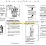
4.1 Checking Mechanical Installation . . . . . . . . . . . . . . . . . . . . . . . . . . . . . . . . . . . . . . . . 49
4.2 Testing MPAC 550 Controller and Initializing Automatic Transfer Mechanism . . 52
4.3 Operation . . . . . . . . . . . . . . . . . . . . . . . . . . . . . . . . . . . . . . . . . . . . . . . . . . . . . . . . . . . . 54
Section 5 Diagnostics and Troubleshooting . . . . . . . . . . . . . . . . . . . . . . . . . . . . . . . . . . . . . . . . . . . . . . . . . 55
5.1 Terminology . . . . . . . . . . . . . . . . . . . . . . . . . . . . . . . . . . . . . . . . . . . . . . . . . . . . . . . . . . 55
5.2 Diagnostics . . . . . . . . . . . . . . . . . . . . . . . . . . . . . . . . . . . . . . . . . . . . . . . . . . . . . . . . . . . 55
5.3 Checking Fuses . . . . . . . . . . . . . . . . . . . . . . . . . . . . . . . . . . . . . . . . . . . . . . . . . . . . . . . 55
5.4 Troubleshooting . . . . . . . . . . . . . . . . . . . . . . . . . . . . . . . . . . . . . . . . . . . . . . . . . . . . . . . 57
Section 6 Manual Operation . . . . . . . . . . . . . . . . . . . . . . . . . . . . . . . . . . . . . . . . . . . . . . . . . . . . . . . . . . . . . . . 61
Section 7 Parts . . . . . . . . . . . . . . . . . . . . . . . . . . . . . . . . . . . . . . . . . . . . . . . . . . . . . . . . . . . . . . . . . . . . . . . . . . . 63
Appendix A Abbreviations . . . . . . . . . . . . . . . . . . . . . . . . . . . . . . . . . . . . . . . . . . . . . . . . . . . . . . . . . . . . . . . . 67

