Format: PDF (Printable Document)
File Language: English
File Pages: 67
File Size: 0.95 MB (Speed Download Link)
Brand: Kohler
Model: ZCS, ZCB, MMS, MNS, MMT, MNT Automatic Transfer Switches
Book No: tp5663
Type of Document: Operation and Installation Manual
$ 40
These Kohler automatic transfer switches sit between your utility feed and generator, usually in plant rooms, data centers, or commercial buildings, and their whole job is to move the load cleanly when the power situation changes. This manual is what I keep handy when installing, commissioning, or sorting out odd transfer behavior. It walks you through how to set up the switch correctly, verify the power sources, and confirm the controls are doing what they should. If, for example, the switch hesitates to transfer back to utility after a brief outage, this is the document I use to trace the control logic and check that the wiring and settings match the application.
Applications & Use Cases
FAQ
Q: Can I keep a digital copy of this manual on a tablet for field use?
A: Yes, it works well digitally; just make sure you can zoom diagrams clearly and keep an offline copy for sites without internet.
Q: Is it worth printing this manual for on-site work?
A: For installation and troubleshooting, a printed copy is handy so you can mark notes and compare directly at the switch.
Safety Note
Always isolate all power sources and verify they’re de-energized before opening or working inside the transfer switch.
Safety Precautions and Instructions . . . . . . . . I
Introduction . . . . . . . . . . . . . . . . . . . . . . . . . . . . . . i
List of Related Materials . . . . . . . . . . . . . . . . . . . . . . . . . i
Service Assistance . . . . . . . . . . . . . . . . . . . . . . . . ii
Service Information . . . . . . . . . . . . . . . . . . . . . . . . . . . . . ii
Product Information . . . . . . . . . . . . . . . . . . . . . . . . . . . . . ii
Section 1 Specifications . . . . . . . . . . . . . . . . . . . 1
1.1 Standard Features . . . . . . . . . . . . . . . . . . . . . . . . 1
1.2 Optional Features . . . . . . . . . . . . . . . . . . . . . . . . . 1
Section 2 Operation . . . . . . . . . . . . . . . . . . . . . . . 3
2.1 Startup . . . . . . . . . . . . . . . . . . . . . . . . . . . . . . . . . . 3
2.2 Controls and Indicators . . . . . . . . . . . . . . . . . . . . 4
2.3 Automatic Operation . . . . . . . . . . . . . . . . . . . . . . 5
2.3.1 Normal Power Source Failure . . . . . . . 5
2.3.2 Normal Power Source Restoration . . . 6
2.4 Programmed Transition Switch . . . . . . . . . . . . . 7
2.4.1 Normal Power Source Failure . . . . . . . 7
2.4.2 Normal Power Source Restoration . . . 8
Section 3 Model M Accessories . . . . . . . . . . . . 9
3.1 Typical Mounting Locations . . . . . . . . . . . . . . . . 10
3.2 DA-2—Time Delays . . . . . . . . . . . . . . . . . . . . . . . 11
3.3 DA-7—Test Switches . . . . . . . . . . . . . . . . . . . . . . 12
3.4 DA-14—Relay Auxiliary Contacts,
Source Available . . . . . . . . . . . . . . . . . . . . . . . . . . 13
3.5 DA-15—Relay Auxiliary Contacts,
Switch Position . . . . . . . . . . . . . . . . . . . . . . . . . . . 14
3.6 DA-23—Plant Exercisers . . . . . . . . . . . . . . . . . . . 15
3.6.1 Clock Resetting Procedure . . . . . . . . . 16
3.6.2 Initial Setup (Time and Day)
Procedure . . . . . . . . . . . . . . . . . . . . . . . 16
3.6.3 Plant Exercise and Shutdown Timers
Programming Procedure . . . . . . . . . . . 16
3.6.4 Time Resetting Procedure . . . . . . . . . . 17
3.6.5 Reviewing the Program . . . . . . . . . . . . 17
3.6.6 Modifying an Existing Program . . . . . . 17
3.6.7 Manual Override Procedure . . . . . . . . 17
3.6.8 Continuous Manual Operation . . . . . . 17
3.6.9 Ending Continuous Manual
Operation . . . . . . . . . . . . . . . . . . . . . . . . 17
3.7 DA-24—Battery Charger . . . . . . . . . . . . . . . . . . . 18
3.7.1 Specifications . . . . . . . . . . . . . . . . . . . . 18
3.7.2 Installation Connections . . . . . . . . . . . 19
3.7.3 Disconnecting the Charger Before
Replacing or Servicing the Battery . . . 20
3.7.4 Reconnecting the Charger After
Replacing or Servicing the Battery . . . 20
3.7.5 Charging Lead-acid Batteries . . . . . . . 20
3.7.6 Charging Nickel-cadmium
Batteries . . . . . . . . . . . . . . . . . . . . . . . . . 21
3.7.7 Charger Voltage Adjustment . . . . . . . . 21
3.7.8 Charger and Battery Maintenance . . . 21
Section 4 Model Z Accessories . . . . . . . . . . . . 23
4.1 Typical Mounting Locations . . . . . . . . . . . . . . . . 25
4.2 DA-2 through DA-4—Time Delays . . . . . . . . . . . 26
4.3 DA-6, 7—Test Switches . . . . . . . . . . . . . . . . . . . . 27
4.3.1 Two-Position Switch
(Standard and DA-6-F) . . . . . . . . . . . . 27
4.3.2 Three-Position Switch (DA-6-M) . . . . . 27
4.3.3 Four-Position Switch (DA-7-D, H) . . . 27
4.4 DA-8—Bypass Time Delay Switch . . . . . . . . . . . 27
4.5 DA-14—Relay Auxiliary Contacts,
Source Available . . . . . . . . . . . . . . . . . . . . . . . . . . 28
4.6 DA-15—Relay Auxiliary Contacts,
Switch Position . . . . . . . . . . . . . . . . . . . . . . . . . . . 29
4.7 DA-18—Meters . . . . . . . . . . . . . . . . . . . . . . . . . . . 29
4.8 DA-23—Plant Exercisers . . . . . . . . . . . . . . . . . . . 30
4.8.1 Clock Resetting Procedure . . . . . . . . . 31
4.8.2 Initial Setup (Time and Day)
Procedure . . . . . . . . . . . . . . . . . . . . . . . 31
4.8.3 Plant Exercise and Shutdown Timers
Programming Procedure . . . . . . . . . . . 31
4.8.4 Time Resetting Procedure . . . . . . . . . . 32
4.8.5 Reviewing the Program . . . . . . . . . . . . 32
4.8.6 Modifying an Existing Program . . . . . . 32
4.8.7 Manual Override Procedure . . . . . . . . 32
4.8.8 Continuous Manual Operation . . . . . . 32
4.8.9 Ending Continuous Manual
Operation . . . . . . . . . . . . . . . . . . . . . . . . 32
4.9 DA-24—Battery Charger . . . . . . . . . . . . . . . . . . . 33
4.9.1 Specifications . . . . . . . . . . . . . . . . . . . . 33
4.9.2 Installation Connections . . . . . . . . . . . 34
4.9.3 Disconnecting the Charger Before
Replacing or Servicing the Battery . . . 35
4.9.4 Reconnecting the Charger After
Replacing or Servicing the Battery . . . 35
4.9.5 Charging Lead-acid Batteries . . . . . . . 35
4.9.6 Charging Nickel-cadmium
Batteries . . . . . . . . . . . . . . . . . . . . . . . . . 36
4.9.7 Charger Voltage Adjustment . . . . . . . . 36
4.9.8 Charger and Battery Maintenance . . . 36
4.10 DA-26—Area Protection Relay . . . . . . . . . . . . . . 37
4.11 DA-28—Logic Protection Fuses . . . . . . . . . . . . . 37
4.12 DA-29—Manual Operation Switches . . . . . . . . . 37
4.13 DA-34-B—Synchronism Check Relay . . . . . . . . 38
4.14 DA-35-G—Load Shedding Contacts . . . . . . . . . 38
Section 5 Scheduled Maintenance . . . . . . . . . . 41
5.1 Inspection and Service . . . . . . . . . . . . . . . . . . . . 42
5.1.1 General Inspection . . . . . . . . . . . . . . . . 42
5.1.2 Other Inspections and Service . . . . . . 43
5.2 Testing . . . . . . . . . . . . . . . . . . . . . . . . . . . . . . . . . . 43
5.2.1 Weekly Generator Set Exercise . . . . . 43
5.2.2 Monthly Automatic Operation Test . . . 43
5.3 Service Schedule . . . . . . . . . . . . . . . . . . . . . . . . . 44
Section 6 Installation . . . . . . . . . . . . . . . . . . . . . . 45
6.1 Receipt of Unit . . . . . . . . . . . . . . . . . . . . . . . . . . . 45
6.1.1 Inspection . . . . . . . . . . . . . . . . . . . . . . . . 45
6.1.2 Lifting . . . . . . . . . . . . . . . . . . . . . . . . . . . 45
6.1.3 Storage . . . . . . . . . . . . . . . . . . . . . . . . . . 46
6.1.4 Unpacking . . . . . . . . . . . . . . . . . . . . . . . 46
6.2 Mechanical Installation . . . . . . . . . . . . . . . . . . . . 46
6.3 Check Manual Operation . . . . . . . . . . . . . . . . . . . 46
6.4 Electrical Wiring . . . . . . . . . . . . . . . . . . . . . . . . . . 46
6.4.1 AC Power Connections . . . . . . . . . . . . 47
6.4.2 Controller Logic . . . . . . . . . . . . . . . . . . . 48
6.4.3 Accessory and Control
Connections . . . . . . . . . . . . . . . . . . . . . . . . . . . . . 48
6.5 Functional Tests . . . . . . . . . . . . . . . . . . . . . . . . . . 49
6.5.1 Voltage Check . . . . . . . . . . . . . . . . . . . . 49
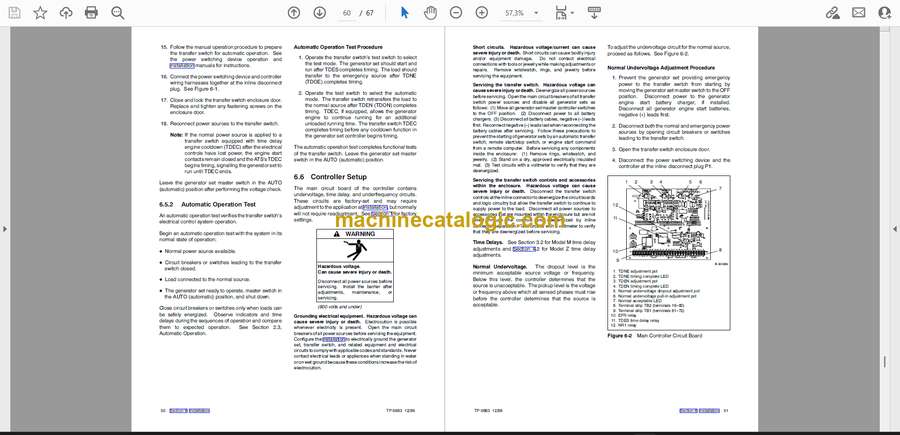
6.5.2 Automatic Operation Test . . . . . . . . . . 50
6.6 Controller Setup . . . . . . . . . . . . . . . . . . . . . . . . . . 50
6.7 Programmed Transition Setup . . . . . . . . . . . . . . 52
6.7.1 Description . . . . . . . . . . . . . . . . . . . . . . . 52
6.7.2 Timing Adjustment for Programmed
Transition . . . . . . . . . . . . . . . . . . . . . . . . 53
Appendix A Abbreviations . . . . . . . . . . . . . . . . . A-1


