Format: PDF (Printable Document)
File Language: English
File Pages: 383
File Size: 30.59 MB (Speed Download Link)
Brand: Komatsu
Model: 730E-10 Dump Truck
Book No: CEAW012302
Serial No: A50051 and up
Type of Document: Field Assembly Manual
$ 39
FOREWORD
CONTENTS
SAFETY INFORMATION
SAFETY NOTICE FOR OPERATION
PRECAUTIONS TO PREVENT FIRE
ACTIONS IF FIRE OCCURS
PRECAUTIONS FOR DISPOSING OF WASTE MATERIALS
ACTIONS TAKEN TO MEET EXHAUST GAS REGULATIONS
PRECAUTIONS FOR DEF
STORE AdBlue/DEF
PRECAUTIONS FOR HANDLING HYDRAULIC EQUIPMENT
PRECAUTIONS FOR DISCONNECTION AND CONNECTION OF PIPINGS
PRECAUTIONS FOR HANDLING ELECTRICAL EQUIPMENT
PRECAUTIONS FOR HANDLING FUEL SYSTEM EQUIPMENT
INSPECTION METHOD OF TIE-OFF ANCHOR POINTS
BE CAREFUL NOT TO HIT BUCKET WHEN RETRACTING WORK EQUIPMENT
SPECIFICATIONS
PRECAUTIONS FOR FIELD ASSEMBLY
DISPOSAL OF REMOVED PARTS
ASSEMBLY PROCEDURE, FACILITY USED, AND SCHEDULE
KIT LAYOUT DIAGRAM
FLOW OF MAIN FIELD ASSEMBLY
TRANSPORTATION
FIELD ASSEMBLY TOOLS LIST
TIGHTENING TORQUE
COATING MATERIALS
SELECTION OF WIRE ROPES USED FOR ASSEMBLY
SELECTION OF NYLON SLINGS USED FOR ASSEMBLY
A. ASSEMBLY OF CHASSIS
A-1 Replacement of return filter (Standard → Flushing)
A-2 Installation of R.H. and L.H. track frames
A-3 Installation of travel piping (PC950)
A-3 Installation of travel piping (PC950LC)
A-4 Installation of step
A-5 Sticking revolving frame sheets
A-6 Installation of L.H. side step
A-7 Installation of L.H. side step (Hydraulic cab step type (if equipped))
A-8 Installation of R.H. side step
A-9 Installation of left side plate
A-10 Installation of right side plate
A-11 Installation of handrail
A-12 Installation of R.H. rearview mirror
A-13 Installation of L.H. rearview mirror
A-14 Sticking counterweight sheets
A-15 Assembly procedure of KomVision camera
A-16 Installation of light above air cleaner
A-17 Installation of counterweight revolving lamp (if equipped)
A-18 Installation of counterweight rear lamp
A-19 Installation of counterweight
A-20 Installation of cab top step lamp
A-21 Installation of cab revolving lamp (if equipped)
A-22 Bleed air from hydraulic pump
A-23 Bleed air from travel motor
A-24 Installation of travel piping covers (PC950)
A-24 Installation of travel piping covers (PC950LC)
A-25 Installation of track frame undercovers
A-26 Installation of travel motor guards
A-27 Adjustment of track tension
A-28 Installation of fire extinguisher (if equipped)
A-29 Installation of transportation jigs (muffler)
A-30 Removal of the self-traveling jig for transporting three kits and installation of the muffler
B. Assembly of work equipment
B-1 Release pressure remaining in hydraulic circuit
B-2 Installation of boom anti-drop valve to boom cylinder
B-3 Installation of boom cylinder to revolving frame
B-4 Installation of auto-grease hose (between injector and circle) (if equipped)
B-5 Installation of boom anti-drop valve hoses (if equipped)
B-6 Installation of boom cylinder hoses
B-7 Bleeding air from cylinder
B-8 Installation of dust seal to boom foot
B-9 Installation of arm dust seal
B-10 Installation of auto-grease hose (between chassis and boom) (if equipped)
B-11 Installation of quick coupler hose (between chassis and boom) (if equipped)
B-12 Installation of boom assembly
B-13 Installation of boom hoses (between machine and boom)
B-14 Installation of arm anti-drop valve hoses (between machine and boom) (if equipped)
B-15 Installation of 1-attachment hoses (between chassis and boom) (if equipped)
B-16 Installation of boom cylinder
B-17 Fixing of boom anti-drop valve hoses (if equipped)
B-18 Installation of quick coupler tubes (arm)
B-19 Installation of arm assembly
B-20 Installation of hoses between boom and bucket cylinder
B-21 Installation of 1-attachment hoses (between boom and arm) (if equipped)
B-22 Installation of auto-grease hose (between boom and arm) (if equipped)
B-23 Installation of quick coupler hose (between boom and arm) (if equipped)
B-24 Installation of bucket assembly
B-25 Clearance standard for installation of work equipment
B-26 Installation of work equipment grease piping
B-27 Installation of work equipment lamp wiring
B-28 Greasing after assembling work equipment
B-29 Bleeding air from auto-grease line (if equipped)
B-30 Bleeding air from hydraulic step cylinder (if equipped)
M. Testing and maintenance procedures after completing assembly
M-1 Check hydraulic tank oil level and add oil
M-2 Flushing of hydraulic circuit
M-3 Replacement of return filter (Flushing → Standard)
M-4 Check of oil and coolant levels at each section
M-5 Places to touch up after field assembly
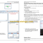
M-6 Setting of KomVision (Camera calibration)
M-7 Inspection method of 12 m visibility (KomVision)
M-8 Check display of failure code
M-9 Installation of fuel tank oil filler lock
M-10 Bleeding air from travel PPC circuit
Field assembly inspection check sheet