The Komatsu 830E-1AC Rigid Dump Truck is a large haul truck used on high‑production mine sites where downtime gets expensive fast. This Shop Manual CEBM027404 is what maintenance teams reach for when a truck is down in the bay and they need a clear, step‑by‑step repair path. People usually use this kind of manual to plan major component work, shorten fault‑finding time, and make sure repairs match OEM procedures so parts and labor don’t get wasted.
What this manual helps you do
- Trace electrical and control issues on the 830E-1AC using wiring information and guided diagnostic steps.
- Check and service the diesel engine, drivetrain, and braking systems following workshop‑level procedures.
- Follow teardown and reassembly sequences for major components so you don’t miss seals, shims, or alignment steps.
- Diagnose hydraulic and mechanical faults in the dump body, steering, and suspension circuits in a structured way.
- Verify adjustments and post‑repair checks so the truck goes back to production without repeat failures.
Who this is for
This shop manual is aimed at field techs, shop mechanics, and fleet managers who schedule and oversee heavy repairs on Komatsu 830E-1AC trucks. It’s not an operator’s handbook or a quick daily check guide; operators and trainees are better off with the Operation & Maintenance manual instead.
FAQ
Q: Is this a searchable PDF I can download and print?
A: Yes, it’s provided as a PDF you can download, search on-screen, and print selected pages for the shop.
Q: Is it detailed enough for full overhauls?
A: These shop manuals are written for dealer‑level and fleet workshops, with the depth you’d expect for full system diagnostics and component rebuilds.
Q: How do I know if it matches my truck’s serial number or variant?
A: You’ll want to match CEBM027404 against your truck’s documentation or ask your Komatsu dealer to confirm coverage for your exact serial and configuration.
Bottom line: If you’re planning or supervising real repair work on Komatsu 830E-1AC haul trucks, this is the right manual; if you just need operating instructions or basic service intervals, keep looking for the O&M book instead.
📘 Show Index
Table of Contents:
- COVER
- 00 CONTENTS AND FOREWORD
- Foreword
- How to Read the Shop Manual
- Safety Alert Symbol and Signal Words
- General Precautions Common to Operation and Maintenance
- Preparations for Safe Operation
- Fire and Explosion Prevention
- Precautions When Getting On or Off the Machine
- Precautions for Cab and Working Around Machine
- Operation Precautions
- Precautions at Jobsite
- Precautions in Starting Engine
- Precautions During Operation
- Maintenance Precautions
- Precautions Before Inspection and Maintenance
- Precautions During Inspection and Maintenance
- Precautions for Electrical Equipment
- Primary Causes of Wiring Harness Failure
- Capacitor Discharge System
- Manual DC link capacitor discharge procedure
- Failure of the discharge system
- Manual discharge of capacitors
- Short isolated capacitor terminals
- Hydraulic Equipment Precautions
- 01 SPECIFICATIONS
- Specifications
- Specifications: 830E-1AC
- Recommended Fuel, Coolant, and Lubricant
- Wheel Motor Oil Specifications
- Suspension Cylinder Oil and Nitrogen Specifications
- 10 STRUCTURE AND FUNCTION
- Cab Air Conditioning
- General Information
- Principles of Refrigeration
- Air Conditioning System Components
- Air Conditioning System Electrical Circuit
- Steering System
- Steering System Layout
- Steering System Operation
- Steering Bleeddown Manifold
- Steering Control Unit
- Steering Accumulators (Piston Type)
- Steering/Brake Pump Operation
- Flow Amplifier Operation
- Hoist System
- Hoist System Layout
- Hoist System Operation
- Hoist Control Valve
- Hydraulic Brake Cabinet – Hoist Components
- Hoist Pilot Valve
- Hoist Limit Solenoid
- Hoist System (Front Wet Brake)
- Brake System
- Service Brake System Layout
- Hydraulic Brake Cabinet Layout
- Service Brake Operation
- Parking Brake Operation
- Brake Lock Operation
- Secondary Braking and Auto Apply
- Brake System (Front Wet Brake)
- Service Brake System Layout
- Hydraulic Brake Cabinet Layout
- Service Brake Operation
- Electrical System, 24V
- Battery Power Supply
- Battery Disconnect Switches
- Engine Starting System
- Auxiliary Control Cabinet Components
- Body-Up Switch Adjustment
- Hoist Limit Switch Adjustment
- Electrical System, AC Drive
- General System Operation
- AC Drive System Components
- DSC Software Functions
- Alternator Field Control
- Event Detection and Processing
- Event Restrictions
- Event Logging and Storage
- Abnormal Conditions/Overriding Functions
- Electronic Accelerator and Retard Pedals
- Drive System Component Abbreviations and Locations
- Reserve Engine Oil System
- Reserve Engine Oil System General Information
- Reserve Engine Oil System Operation
- Remote Tank Fill System
- Automatic Lubrication (Auto Lube) System
- Automatic Lubrication (Auto Lube) Grease Pump and Reservoir
- Automatic Lubrication (Auto Lube) System Operation
- Suspensions
- 20 STANDARD VALUE TABLE
- 30 TEST AND ADJUST
- Hydraulic Systems
- Hydraulic System Checkout Procedures
- Hydraulic System Checkout Sheet
- Steering System Leakage Check
- Toe-In Adjustment
- Hoist Cylinder Leakage Test
- Steering Cylinder Leakage Test
- Checking the Steering/Brake Pump Control Pressures
- Adjusting the Steering/Brake Pump Control Pressures
- High Altitude Steering/Brake Pump Adjustment
- Hydraulic Systems (Front Wet Brake)
- Hydraulic System Checkout Procedures
- Hydraulic System Checkout Sheet
- Brake System
- Brake System Checkout Procedures
- Brake System Checkout Sheet
- Brake Bleeding Procedure
- Parking Brake Adjustment Procedure
- Piston Assembly Return Spring Force and Built-in Clearance (BIC)
- Piston Assembly Adjuster Grip Force
- Adjuster Force
- Piston Return Spring
- F-type Piston Assembly Return Spring Force and Built-in Clearance (BIC)
- Adjuster Pin Installation
- Piston Return Spring
- Adjuster Pin and Adjuster Sleeve
- Front Service Brake Conditioning (Burnishing)
- Rear Service Brake Conditioning (Burnishing)
- Brake System (Front Wet Brake)
- Brake System Checkout Procedures
- Brake System Checkout Sheet
- Wet Disc Brake Bleeding Procedure
- Brake Piston Leakage Test
- Brake Seal Pressure Test
- Oil Separator Seal Pressure Test
- Wet Disc Brake Wear Inspection
- Disconnecting Front Wet Brakes for Rear Brake Burnishing
- Accumulators and Suspensions
- Bladder Accumulator Charging Procedure
- Bladder Accumulator Leakage Test
- Bladder Accumulator Storage
- Piston Accumulator Charging Procedure
- Piston Accumulator Leakage Test
- Piston Accumulator Storage
- Check for Improper Suspension Charge
- Suspension Oiling and Charging Procedures
- Oiling and Charging Tools and Support Blocks
- Nitrogen Charging Kit Installation
- Nitrogen Charging Kit Removal
- Front Suspension Oiling and Charging
- Rear Suspension Oiling and Charging
- Suspension Pressure Test
- Automatic Lubrication (Auto Lube) System
- Prime the Auto Lube Pump
- Prime the Auto Lube Grease Lines
- Auto Lube System Checkout
- Adjust the Auto Lube Cycle Timing
- Adjust the Auto Lube Cycle Timing
- Cab Air Conditioning
- Refrigerant Leak Detection
- A/C System Performance Test
- Check the A/C System Oil
- A/C System Flushing Procedure
- Manifold Gauge Set Installation
- Purging Air From The Service Hoses
- Refrigerant: Recycled vs Reclaimed
- Refrigerant Recovery Procedure
- Evacuate the A/C System
- Charge the A/C System
- Electrical Systems
- Electrical System Checkout Procedures
- Visual Checks
- Voltage Checks
- Truck Function Checks
- Interface Module (IM) Checks
- KOMTRAX Plus Checks
- Payload Meter (PLM) Checks
- Engine Delayed Shutdown Smart Timer Check
- Hoist Limit Switch Check
- Electrical System Checkout Sheet
- Electrical System, AC Drive
- AC Drive System Electrical Checkout Procedure
- AC Drive System Maintenance
- Normal Shutdown Procedure
- Test Equipment
- Handling Electronic Panel Printed Circuit Cards
- Rest Mode Activation
- Initial Checkout Procedures
- Circuit Continuity and Resistance Checks
- Megger Test for Grounds
- Troubleshooting for Grounds
- Low Voltage Power Supply Checks
- Power Supply Check Procedure
- Drive System Controller (DSC) Card Checks
- Propulsion System Software Installation
- DSC Manual Test Procedures
- Accelerator Pedal, Retarder Pedal, and Retarder Lever Checks
- Set Truck ID Number
- Control Cabinet Pressure Switch Check
- Checks Prior To Self Load Engine Test (Loadbox)
- Engine Running Tests
- Battery Boost Verification
- Selector Switch Check
- Ground Detection Network Tests
- Ground Detection Feedback Circuit Static Test
- DC Link Positive Side Ground Check
- DC Link Negative Side Ground Check
- Self Load Test (Loadbox) Procedure
- Diagnostic Information Display (DID) Panel Checks
- Viewing Event and Statistical Data
- Viewing the DSC Event Summary, Trigger Data, and Data Packs
- Viewing the Statistical Data
- Logic Screens
- Datalogger Function
- Setting Up the Datalogger
- Starting the Datalogger
- Uploading Data
- Consolidated Truck Data Save
- USB Drive
- Interface Module (IM)
- Interface Module Removal
- Interface Module Installation
- Temperature Sensors
- Pressure Sensors
- Interface Module Software and Tools
- Flashburn Program Installation
- Flashburn Program Installation
- IM Application Code Installation
- Interface Module Realtime Data Monitor Software Program
- Interface Module Checkout Procedure
- Check for Inputs and Outputs from the Interface Module
- Check Digital Inputs to the Interface Module
- Check Analog Inputs to the Interface Module
- Check Can RPC & J1939 Interfaces to the Interface Module
- Check Outputs from the Interface Module
- Interface Module 2 (IM2)
- Interface Module 2 Software and Tools
- Program the IM2 Controller
- Interface Module 2 Checkout Procedures
- Check for IM Fault Codes
- Checking Digital Inputs to the IM2
- Checking Analog Inputs to the IM2
- Checking Serial Communication to the IM
- Checking Outputs from the IM2
- Interface Module 2 Checkout Sheet
- Payload Meter IV
- Payload Meter IV Software and Tools
- Payload Meter IV System Configuration
- Configuring a Static IP Address
- Payload Meter IV Software Installation
- Payload Meter IV Data Downloading
- Payload Meter IV Checkout Procedure
- Payload Meter IV Checkout Sheet
- KOMTRAX Plus
- KOMTRAX Plus Software and Tools
- KOMTRAX Plus Controller Setup Procedure
- Precautions When Replacing the KOMTRAX Plus Controller
- KOMTRAX Plus Controller Checkout Procedure
- Preliminary steps
- Checkout Procedure
- Camera System
- Camera System
- Camera Monitor
- Camera Setup and Checkout Procedure
- Step 1: Switch Function
- Step 2: Monitor System Settings to Default
- Step 3: Monitor Settings – System Settings
- Step 4: Monitor Settings – Sytem Settings – Camera Settings
- Step 5: Monitor Settings – System Settings – On Screen Display
- Step 6: Monitor Settings – System Settings – Standby Mode
- STEP 7: Integrated Functions Check
- Komatsu Wireless Bridge (Optional)
- 40 TROUBLESHOOTING
- Fuses, Diodes and Relays
- AC Drive System Fault Codes (DSC)
- Event Restrictions
- DSC Event List
- Inverter Event List
- DID Panel Fault Codes
- Standard Truck Fault Codes
- A001
- A002
- A003
- A004
- A005
- A006
- A007
- A008
- A009
- A010
- A011
- A013
- A014
- A016
- A017
- A018
- A019
- A022
- A101
- A103
- A104
- A105
- A107
- A108
- A109
- A111
- A115
- A117
- A118
- A123
- A124
- A125
- A126
- A127
- A128
- A139
- A152
- A153
- A154
- A155
- A158
- A184
- A190
- A193
- A198
- A199
- A200
- A201
- A202
- A203
- A204
- A205
- A206
- A207
- A212
- A213
- A214
- A216
- A223
- A230
- A231
- A233
- A235
- A236
- A237
- A240
- A242
- A243
- A244
- A245
- A246
- A247
- A248
- A249
- A250
- A251
- A252
- A253
- A255
- A256
- A257
- A258
- A260
- A261
- A262
- A264
- A265
- A266
- A267
- A268
- A270
- A271
- A272
- A273
- A274
- A275
- A276
- A277
- A278
- A279
- A280
- A281
- A282
- A283
- A284
- A285
- A286
- A292
- A303
- A304
- A305
- A307
- A309
- A310
- A311
- A312
- A313
- A315
- A316
- A318
- A320
- A321
- A322
- A323
- A324
- A325
- A326
- A327
- A328
- A329
- A330
- A332
- A333
- A334
- A335
- A350
- A351
- A352
- A353
- A354
- A355
- A356
- A357
- A358
- A359
- A360
- A361
- A362
- A363
- A364
- A365
- KomVision Fault Codes
- Troubleshoot the Steering System
- Steering System Troubleshooting Guide
- Basic Hydraulic System Checks
- Steering/Brake Pump Troubleshooting Guide
- Steering/Brake Pump Troubleshooting Checks
- Steering/Brake Pump Fails to Unload
- Steering/Brake Pump Fails to Develop Pressure
- Steering/Brake Pump Slow to Develop Pressure
- Steering/Brake Pump Control Valve Inspection
- Steering/Brake Pump Case Drain Check
- Troubleshoot the Auto Lube System
- Troubleshoot the HVAC System
- HEATER / AIR CONDITIONER CONTROLS
- Diagnostics Mode
- Error Codes
- Advanced Diagnostics
- Firmware Version
- Additional HVAC Troubleshooting Chart
- Voltage Levels
- Reserve Engine Oil System
- Circuit fuses
- Pumping unit LED signals
- 50 DISASSEMBLY AND ASSEMBLY
- Special Tools List
- Wheels, Spindles and Rear Axle
- General Precautions for Tires and Rims
- Lubricants for Tire and Rim Service
- Tire Inflation
- Rim Components
- Wheel Stud Maintenance
- Rear Outer Wheel Stud Installation
- Front Wheel Removal
- Front Wheel Installation
- Rear Wheel Removal
- Rear Wheel Installation
- Lock Ring Removal
- Lock Ring Installation
- Tire Removal (Front 5-Piece Rim)
- Tire Removal (Rear Outer 7-Piece Rim)
- Tire Removal (Rear Inner 5-Piece Rim)
- Tire and Rim Preparation
- Tire Installation (Front 5-Piece Rim)
- Tire Installation (Rear Inner 5-Piece Rim)
- Tire Installation (Rear Outer 7-Piece Rim)
- Front Wheel Hub and Spindle Removal
- Spindle Removal While Off the Truck
- Front Wheel Hub and Spindle Installation
- Spindle, Hub and Brake Assembly Cross-Section View
- Front Wheel Hub and Spindle Disassembly
- Front Wheel Hub and Spindle Cleaning and Inspection
- Front Wheel Hub and Spindle Assembly
- Wheel Bearing Adjustment (On Truck)
- Hub Floating Seal Installation
- Rear Axle Removal
- Rear Axle Cleaning and Inspection
- Rear Axle Installation
- Anti-Sway Bar Removal
- Anti-Sway Bar Installation
- Pivot Pin Removal
- Pivot Pin Installation
- Pivot Eye Bearing Wear Inspection
- Pivot Eye Bearing Replacement
- Pivot Eye Removal
- Pivot Eye Installation
- Wheel Motor Removal
- Wheel Motor Cleaning and Inspection
- Wheel Motor Installation
- Wheels, Spindles and Rear Axle (Front Wet Brake)
- Front Wheel Hub and Spindle Removal
- Spindle Removal While Off the Truck
- Front Wheel Hub and Spindle Installation
- Spindle, Hub and Brake Assembly Cross-Section View
- Front Wheel Hub and Spindle Disassembly
- Front Wheel Hub and Spindle Cleaning and Inspection
- Front Wheel Hub and Spindle Assembly
- Floating Seal Installation
- Steering System
- Steering Control Unit Removal
- Steering Column Spline Inspection
- Steering Control Unit Installation
- Steering Control Unit Disassembly
- Steering Control Unit Assembly
- Steering Column Removal
- Steering Column Installation
- Steering Wheel Removal
- Steering Wheel Installation
- Bleeddown Manifold Removal
- Bleeddown Manifold Installation
- Flow Amplifier Removal
- Flow Amplifier Installation
- Steering Pin Joint Wear Inspection
- Tie Rod Removal
- Tie Rod Installation
- Steering Cylinder Removal
- Steering Cylinder Installation
- Steering Cylinder Disassembly
- Steering Cylinder Cleaning and Inspection
- Steering Cylinder Assembly
- Steering/Brake Pump Removal
- Steering/Brake Pump Installation
- Piston Steering Accumulator Removal
- Piston Steering Accumulator Installation
- Piston Steering Accumulator Disassembly
- Piston Accumulator Cleaning and Inspection
- Piston Seal Replacement
- Piston Steering Accumulator Assembly
- Brake System
- Brake Treadle Valve Removal
- Brake Treadle Valve Installation
- Brake Valve/Pedal Disassembly
- Brake Valve/Pedal Assembly
- Brake Bladder Accumulator Removal
- Brake Bladder Accumulator Installation
- Brake Manifold Removal
- Brake Manifold Installation
- Brake Manifold Component Replacement
- Front Brake Caliper Removal
- Front Brake Caliper Installation
- Front Brake Caliper Disassembly
- Front Brake Caliper Cleaning and Inspection
- Front Brake Caliper Assembly
- Rear Brake Caliper Removal
- Rear Brake Caliper Installation
- Rear Brake Caliper Disassembly
- Rear Brake Caliper Cleaning and Inspection
- Rear Brake Caliper Assembly
- Rear Brake Caliper Disassembly (F-type Piston)
- Rear Brake Caliper Assembly (F-type Piston)
- Brake System (Front Wet Brake)
- Front Brake Dual Relay Valve Removal
- Front Brake Dual Relay Valve Installation
- Rear Brake Dual Relay Valve Removal
- Rear Brake Dual Relay Valve Installation
- Front Wheel Brake Disassembly
- Wheel Brake Cleaning and Inspection
- Front Wheel Brake Assembly
- Wet Disc Brake Friction Disc Inspection
- Wet Disc Brake Separator Plate Inspection
- Friction Disc and Separator Plate Checkout Sheet
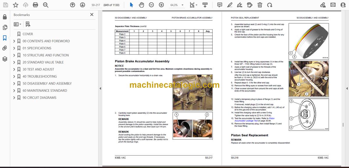
- Piston Brake Accumulator Assembly
- Piston Seal Replacement
- Piston Accumulator Cleaning and Inspection
- Piston Brake Accumulator Disassembly
- Piston Brake Accumulator Installation
- Piston Brake Accumulator Removal
- Hoist System
- Hoist Pump Removal
- Hoist Pump Installation
- Hoist Pump Disassembly
- Hoist Pump Inspection
- Hoist Pump Assembly
- Hoist Control Valve Removal
- Hoist Control Valve Installation
- Hoist Control Valve Service
- Hoist Control Valve O-Ring Replacement
- Inlet Section Assembly
- Inlet Section Disassembly
- Spool Section Disassembly
- Spool Section Assembly
- Overcenter Manifold Service
- Hoist Pilot Valve Removal
- Hoist Pilot Valve Installation
- Hoist Pilot Valve Disassembly
- Hoist Pilot Valve Cleaning and Inspection
- Hoist Pilot Valve Assembly
- Hoist Cylinder Removal
- Hoist Cylinder Installation
- Hoist Cylinder Disassembly
- Hoist Cylinder Cleaning and Inspection
- Quill Installation
- Quill Check Ball and Plug Installation
- Hoist Cylinder Assembly
- Hoist System (Front Wet Brake)
- Hoist Control Valve Removal
- Hoist Control Valve Installation
- Hoist Control Valve Service
- Hoist Control Valve O-Ring Replacement
- Inlet Section Disassembly
- Inlet Section Assembly
- Front Spool Section Disassembly
- Front Spool Section Assembly
- Rear Spool Section Disassembly
- Rear Spool Section Assembly
- Overcenter Manifold Service
- Suspensions
- Front Suspension Removal
- Front Suspension Cleaning and Inspection
- Front Suspension Installation
- Front Suspension Bolted Joint Inspection
- Front Suspension Charging Valve Replacement
- Front Suspension Disassembly
- Front Suspension Assembly
- Rear Suspension Removal
- Rear Suspension Installation
- Rear Suspension Charging Valve Replacement
- Rear Suspension Disassembly
- Rear Suspension Cleaning and Inspection
- Rear Suspension Assembly
- Dump Body and Structures
- Dump Body Removal
- Dump Body Inspection
- Dump Body Installation
- Body Pads Removal
- Body Pads Installation
- Body Pad Shimming Procedure
- Diagonal Ladder Removal
- Diagonal Ladder Installation
- Egress Gate Adjustment
- RH Deck Removal
- RH Deck Installation
- LH Deck Removal
- LH Deck Installation
- Fuel Tank Removal
- Fuel Tank Cleaning and Inspection
- Fuel Tank Installation
- Fuel Tank Vent Disassembly
- Fuel Tank Vent Assembly
- Fuel Gauge Sender Removal
- Fuel Gauge Sender Installation
- Hydraulic Tank Removal
- Hydraulic Tank Installation
- Hydraulic Tank Strainers Removal
- Hydraulic Tank Strainers Cleaning and Inspection
- Hydraulic Tank Strainers Installation
- Operator Cab
- Operator Cab Removal
- Operator Cab Installation
- Cab Door Removal
- Cab Door Installation
- Door Panel Removal
- Door Panel Installation
- Window Regulator Removal
- Window Regulator Installation
- Door Glass Removal
- Door Glass Installation
- Door Seal Replacement
- Replacing Door Assembly Seal and Door Hinge Seal
- Replacing Door Opening Seal
- Outer Door Seal Replacement
- Interior Door Handle and Door Latch Removal
- Interior Door Handle and Door Latch Installation
- Door Jamb Bolt Adjustment
- Poor Seal When Door Is Closed
- Door Springs Back Open
- Door Handle Plunger Adjustment
- Side Window Glass Removal
- Side Window Glass Installation
- Windshield Glass Removal
- Rear Window Glass Removal
- Windshield Glass Installation
- Rear Window Glass Installation
- Windshield Wiper Motor Removal
- Windshield Wiper Motor Installation
- Windshield Wiper Arm Removal
- Windshield Wiper Arm Installation
- Windshield Wiper Linkage Removal
- Windshield Wiper Linkage Installation
- Cab Seat Inspection
- Operator Seat Removal
- Operator Seat Installation
- Seat Compressor Replacement
- Passenger Seat Removal
- Passenger Seat Installation
- Cab Seat Servicing
- Seat Belt Removal (Standard Seat)
- Seat Belt Installation (Standard Seat)
- Seat Belt Service (Optional Seats)
- Seat Belt Removal (Optional Seat)
- Seat Belt Installation (Optional Seat)
- Camera System
- Camera Controller Removal
- Camera Controller Installation
- Camera Switcher Removal
- Camera Switcher Installation
- Power Module
- Power Module General Information
- Power Module Removal
- Power Module Installation
- Exhaust Tube Installation
- Exhaust Blanket Installation
- Alternator Removal
- Radiator Removal
- Alternator Installation
- Measuring and Shim Calculation
- Joining the Alternator and the Engine
- Radiator Installation
- Radiator Internal Inspection
- Radiator External Cleaning
- Radiator Disassembly
- Radiator Cleaning and Inspection
- Radiator Assembly
- Engine Removal
- Engine Service
- Engine Installation
- 60 MAINTENANCE STANDARD
- Rules for Maintenance
- Torque Specifications
- Shutting Down the Machine
- Hydraulic System Bleeddown Procedure
- Hydraulic System Vacuum Procedure
- Long Term Storage of Electric Dump Truck
- Hydraulic Pumps
- Steering/Brake Pump
- Hoist Pump
- Wet Disc Brakes
- Tie Rod
- Tail Lights, Clearance Lights and Turn Signals
- 90 CIRCUIT DIAGRAMS
- CONTENTS: 830E-1AC
- CONTENTS: 830E-1AC With Front Wet Disc Brakes
Komatsu


