The Komatsu 860E-1KT Rigid Dump Truck is a large mine haul truck used for moving heavy overburden and ore all day, every day. The Komatsu 860E-1KT Rigid Dump Truck Shop Manual (CEBM032004) is what shops usually reach for when the truck is down and they need to repair, not just operate or inspect it. People use this kind of manual when they’re tearing into major components, chasing electrical or hydraulic faults, or signing off on big repairs that can’t afford a repeat failure.
What this manual helps you do
- Trace electrical issues using wiring information so you’re not guessing with a test light in the dirt.
- Diagnose hydraulic and brake problems by following step‑by‑step test and inspection procedures.
- Follow disassembly and reassembly sequences for major components like powertrain, suspension, and structural parts.
- Check adjustment procedures for systems that affect braking, steering, and haul performance after a repair.
- Verify correct inspection points and standard workshop practices before returning the truck to production.
Who this is for
This shop manual is aimed at field technicians, dealer or mine-site shop mechanics, and maintenance planners who support the Komatsu 860E-1KT. Operators or new trainees looking for basic controls and daily checks would be better off with the Operation & Maintenance Manual instead of this one.
FAQ
Q: Is this a PDF I can download and search?
A: Yes, it’s a digital PDF you can download, search by keyword, and print selected pages for use in the field.
Q: Does it go deep enough for full overhauls and major repairs?
A: Yes, the Komatsu 860E-1KT Rigid Dump Truck Shop Manual walks through diagnostic procedures, disassembly sequences, and workshop-level repair steps.
Q: How do I know if it matches my truck’s exact build or options?
A: Match your truck’s model and use the book reference CEBM032004, then confirm any variant‑specific details against your machine plate and local dealer.
If you’re the person responsible for getting an 860E-1KT back in the haul cycle after a failure, this is the manual you want; if you just need operating tips or basic maintenance intervals, keep looking for the O&M manual instead.
📘 Show Index
Table of Contents:
- COVER
- 00 Index and foreword
- Index
- Composition of shop manual
- Table of contents
- Foreword, safety and general information
- Foreword
- How to read the shop manual
- Composition of shop manual
- Revision and distribution
- Symbols
- General safety
- Safety rules
- Safety features
- Fire extinguisher and first aid kit
- Clothing and personal items
- Leaving the operator seat
- Mounting and dismounting
- Fire prevention for fuel and oil
- Precautions with high temperature fluids
- Asbestos dust hazard prevention
- Prevention of injury by work equipment
- Unauthorized modification
- Precautions when using ROPS
- Precautions for attachments
- Precautions for starting the truck
- Precautions before operating the truck
- Safety at the worksite
- Fire prevention
- Ventilation in enclosed areas
- Preparing for operation
- Mirrors, windows and lights
- In operator cab (before starting the engine)
- Seat Belts
- Precautions while operating the truck
- When starting the engine
- General truck operation
- Ensuring good visibility
- Traveling
- Traveling in reverse
- Traveling on slopes
- Operating on snow or ice
- Avoid damage to dump body
- Driving near high voltage cables
- When dumping
- Working on loose ground
- When loading
- Parking the truck
- Towing
- Working near batteries
- Battery hazard prevention
- Starting with jumper cables
- Jump starting with receptacles
- Precautions before performing service
- Warning tag
- Stopping the engine
- Proper tools
- Use of tie-off anchor during maintenance and repair
- The anchor must not be used for lifting. Tie-off anchor installation
- Securing the dump body
- While performing maintenance
- Keep the truck clean
- Attachments
- Working under the truck
- Rotating fan and belts
- Adding fuel or oil
- Use of lighting
- Radiator coolant level
- Precautions with the battery
- Precautions with high pressure oil
- Handling high pressure hoses
- Precautions when performing maintenance near high temperature or high pressure
- Waste materials
- Tires
- Handling tires
- Storing tires after removal
- Precautions for performing repairs
- Engine shutdown procedure after AC drive system failure
- Jack point locations
- Precautions for lifting components
- Precautions for welding on the truck
- Handling electrical equipment and hydraulic components
- Points to remember when handling electrical equipment
- Points to remember when handling hydraulic equipment
- How to Read Electric Wire Code
- Color Code and Harness Designation Tables
- Standard torque tables
- Effect of special lubricants on fasteners and standard torque values
- Suggested sources for rust preventive grease
- SAE grade 5 and grade 8 hex head capscrew and nut assemblies
- SAE grade 9 capscrews
- Class 10.9 capscrews and class 10 nuts
- Standard tightening torques for fittings
- Standard tightening torques for clamps
- Conversion tables
- Common conversion multipliers
- Operating instructions
- Preparing for operation
- Engine start-up
- After engine start-up
- Precautions during truck operation
- Operating on a haul road
- Starting on a grade with a loaded truck
- Passing
- Loading
- Overload speed limit function
- Dumping
- Raising The Dump Body
- Lowering The Dump Body (When dumping on flat ground):
- Lowering The Dump Body (When dumping over a berm or into a crusher):
- Trolley operating instructions
- Operating in trolley line mode
- Getting on line
- Operating on trolley
- Getting off line
- Line status signals
- Trolley disconnect
- Traffic consideration for trolley line operation
- Approaching slow moving vehicles in a trolley assisted truck
- Operating slow moving vehicles on trolley assist ramps
- Truck failure while on trolley
- Using the speed control feature
- Safe parking procedures
- Normal engine shutdown procedure
- Sudden loss of engine power
- Fuel depletion
- Towing
- Special Wiring Harness
- Towing Procedure
- Disabled truck operation
- Steering and brake system
- Components Required
- Hookup
- Disabled truck dumping procedure
- Hookup
- Raising the Body
- Lowering the Body
- 01 Specification
- Specification and technical data
- Specification drawing
- Specifications
- Weight table
- Fuel, coolant and lubricants
- Mixing rate of water and anti-freeze
- Suspension cylinder oil and nitrogen specifications
- 10 Structure and functions
- Cab air conditioning
- General information
- Environmental impact of air conditioning
- Air conditioning for off-highway vehicles
- Principles of refrigeration
- Air conditioning
- Refrigeration – the act of cooling
- The refrigeration cycle
- Air conditioning system components
- Relays
- Fan motor and speed control
- Cab air filter
- Heater core
- Actuators
- Compressor (refrigerant pump)
- Service valves
- Condenser
- Receiver-drier
- Expansion valve
- Accumulator
- Evaporator core
- Air conditioning system electrical circuit
- Thermostat
- Compressor clutch
- Trinary™ switch
- Steering circuit
- Steering circuit operation
- Steering circuit components
- Steering control unit
- High pressure filter
- Steering accumulators
- Bleeddown manifold
- Steering accumulator bleeddown solenoid
- Quick disconnect ports
- Hoist up limit solenoid
- Flow amplifier
- Flow amplifier operation
- No steer
- Steering left
- Steering right
- No steer, external shock load
- Steering/brake pump operation
- Normal operation
- Neutral position
- Full pump volume
- Half pump volume
- Steering cylinder wear data
- Hoist circuit
- Hoist circuit operation
- Hoist circuit components
- Hydraulic tank
- Hoist pump
- High pressure filters
- Hoist valve
- Hoist limit solenoid
- Pilot operated check valve
- Hoist pilot valve
- Overcenter manifold
- Hoist pilot valve operation
- Float position of pilot valve with truck body on frame
- Power up operation
- Hold operation
- Power down operation
- Float operation
- Hoist cylinder wear data
- Brake circuits
- General information
- Service brake circuit operation
- Secondary braking system and auto apply
- Rear wheel brake lock circuit operation
- Parking brake circuit operation
- Normal operation (engine start switch ON, engine on)
- Brake lines and test ports
- Brake warning circuit operation
- Brake assembly wear data
- Suspensions
- General information
- Front suspension wear data
- Rear suspension wear data
- Electrical system, 24 volt
- Battery supply system
- Auxiliary control cabinet components
- 24VDC to 12VDC converter
- Diode board – DB1
- Power distribution terminals
- Control power relay
- Fuse blocks
- Relay boards
- Relay boards RB1, RB3, RB4, RB5
- Relay boards RB6, RB7, RB8, RB9
- Relay functions
- Body position switches (With proximity switch and metal arm)
- Body-up switch
- Hoist limit switch
- Body position switches (With proximity switch and magnet)
- Proximity switch operation
- Body-up Switch
- Hoist limit switch
- Interface module (IM)
- General information
- Service
- Sensors
- Temperature sensors
- Pressure sensors
- Interface module inputs and outputs
- Drive system
- SR rectifier module
- ST module (auxiliary voltage inverter)
- SD phase modules
- SR/ST/SD module removal
- Inverter cabinet layout
- Inverter cabinet water flow
- Field regulator
- Field regulator (discharge resistor)
- Gate Unit
- Technical Data
- Technical Data
- Technical Data
- Control power filter
- Filter for TCU
- Terminal block bus bar
- Fuses (analog sensor voltage)
- Fuses (field regulator)
- Technical Data
- Fuses (fuse holder for field regulator)
- Fuses (control power and trolley box contactor)
- Diode modules
- Support capacitors
- 3-Phase capacitor bank (for ST module output voltage)
- Air-cooled inductors (for ST module)
- 3-Phase transformer (for ST module)
- Diagnostics box
- Diagnostic and system monitoring panel
- Current transducers
- Device names:
- Technical Data
- Technical Data
- Current transducers (for ST module output)
- Voltage transducers
- Voltage transducers (for ST module output)
- Voltage transducers (SiBAS® 24V DC bus monitoring)
- Analog inclinometer
- DC link capacitors
- Ground tie capacitor
- Low-inductance bus bar assembly
- Free-wheeling diode for low-inductance bus bars
- Contactor (grid box and main blower motor)
- Contactor (control power)
- Contactor (DC contactors)
- Contactor (crowbar bypass)
- Temperature probes (PT100 style)
- Coolant inlet temperature sensor
- Coolant outlet temperature sensor (external pad style)
- IGBT module heat sink temperature sensor
- Coolant outlet temperature sensor (internal style)
- Coolant outlet temperature sensor (external pad style)
- Circuit breakers
- Inner circulating blower fan
- Coolant pump
- Motor for coolant pump
- Coolant pressure sensor
- Inner radiator
- Ground voltage monitoring resistors
- Protection thyristor assembly (crowbar)
- Discharge reactor
- Main blower motor
- Grid box
- Grid box blower motor
- Grid box blower motor grease fittings
- Main alternator
- Stator
- Rotor
- Bearings
- Electrical connection
- Cooling and ventilation
- Rotating rectifier section
- Technical Data
- Main alternator circuit diagram
- IGBT – inverter/chopper phase module
- Troubleshooting information
- Main input rectifier module
- Upper ground tie resistor
- Lower ground tie resistor
- Troubleshooting – fault diagnosis
- Speed sensor, alternator
- Speed sensors, wheel motors
- Traction motor
- Grid box
- Device name: M04
- Technical Data
- Step down box
- SIBAS® IGBT rack components
- SiBAS®32 Traction Control Unit (TCU)
- Overview of the SiBAS®32 systems
- Features
- General technical specifications, operating conditions
- Permissible temperature range
- Permissible limit value for air humidity
- Permissible power supply voltage range
- Permissible mechanical loads
- Protection measures against electrical hazards
- Application
- Removing and installing the SiBAS®32 cards
- Removal with 24V OFF! (ESD protection required)
- Installation with 24V OFF! (ESD protection required)
- SiBAS®32 card device names
- Structure of SiBAS®32 card part number
- Development status, downward compatibility
- SiBAS®32 card interchangeability
- Use of service interfaces
- Connection of the service unit
- Maintenance
- Cleaning
- SiBAS®32 card interactions
- Blower subassembly
- Device name: N/A
- Application
- Battery replacement
- Rules for handling lithium batteries
- Replacement of the battery in the fan subassembly
- CPU card
- Device name: G011
- Application
- Front panel
- Technical data
- DSP card
- Device name: G019, G027 and G35
- Application
- Front panel
- Technical data
- I/O card
- Device name: G043
- Application
- Front panel
- Technical data
- TRACO card (optional)
- Device name: G003
- Application
- Front panel
- Technical data
- Input voltage/frequency card
- Device name: L055, L063 and L071
- Application
- Technical data
- I/O analog card
- Device name: L079 and L087
- Technical data
- I/O analog card
- Device name: L095 and L103
- Application
- Technical data
- Output pulse amplifier card
- Device name: L115, L123, L131, L139 and L147
- Application
- Technical data
- Input temperature sensor card
- Device name: L155 and L163
- Application
- Technical data
- UWS card
- Device name: G055, G063, G071 and G079
- Application
- Technical data
- Digital input card
- Device name: G103, G111, G119, G127 and G135
- Application
- Technical data
- Power start-up unit card
- Device name: G163
- Application
- Technical data
- Binary output contactor drive card
- Device name: C019, C027 and C035
- Application
- Technical data
- 24V / 24V power supply
- Device name: C045, C105, C129
- Application
- Testing the power supply card
- Technical data
- 24V / 15V power supply
- Device name: C069, C087
- Application
- Testing the power supply card
- Technical data
- 24V / 5V power supply
- Device name: C153
- Application
- Testing the power supply card
- Technical data
- Reserve engine oil system
- General information
- Operation
- Remote tank fill system
- Wheel motor transmission
- General information
- Transmission wear data
- 20 Standard value table
- Standard value table
- Standard value table for truck
- 30 Testing and adjusting
- Service tools
- Special tool list
- Control cabinet
- Cab air conditioning
- General information
- Service tools and equipment
- Recovery/recycle station
- Leak detector
- Manifold gauge set
- Service valves
- Vacuum pump
- Detecting leaks
- System performance test
- Checking system oil
- System flushing
- Installing the manifold gauge set
- Purging air from the service hoses
- Recovering and recycling refrigerant
- Draining oil from previous recovery cycle
- Recovery cycle
- Recycling procedure
- Evacuating the air conditioning system
- Charging the air conditioning system
- Steering, brake cooling and hoist hydraulic system
- General information on system checkout
- Steering system checkout procedures
- Steering pump pressure control adjustments
- Steering control valve and flow amplifier leakage test
- Bleed down manifold leakage test
- Shock and suction valve pressure tests
- Steering system checkout data sheet
- Toe-in adjustment
- Brake cooling and hoist system checkout procedures
- Pressure gauge locations
- Brake cooling circuit test
- Power up relief pressure test
- Power down relief pressure test
- Counterbalance valve pressure check
- Counterbalance valve adjustment
- Brake cooling and hoist system checkout data sheet
- Hydraulic system flushing procedure
- Front suspension pressure test
- Rear suspension pressure test
- Steering cylinder leakage test
- Hoist cylinder leakage test
- Brake system
- General information on system checkout
- Brake circuit checkout procedure
- Precheckout items
- Software operation and configuration
- Hydraulic isolation and troubleshooting
- Truck starting procedure
- Initial system setup
- Brake lock / secondary braking checkout
- Brake lock hydraulic circuit trouble shooting guide
- Parking brake checkout
- Park brake hydraulic circuit trouble shooting guide:
- Service brake checkout
- Blended braking checkout
- Low brake accumulator pressure and auto apply checkout
- Reapplication
- Parking brake control logic checkout
- Brake lock control logic checkout
- BLENDED BRAKING CHECKOUT
- Brake piston leakage test
- Wet disc brake bleeding procedure
- Parking/service brake bleeding procedure
- Parking brake leakage test
- Brake disc wear inspection
- Brake valve bench test and adjustment
- Test setup procedure
- Brake valve output pressure adjustment
- Final test and adjustment
- Accumulators and suspensions
- Accumulator charging and storage
- Accumulator charging procedures
- Precharge maintenance
- Accumulator storage procedure
- Accumulator leak testing
- Checking for improper suspension charge on operating trucks
- Suspension oil change recommendations
- Suspension oiling and charging procedures
- Required equipment
- Installing the charging kit
- Removing the charging kit
- Support blocks for oiling and charging dimensions
- Front suspensions
- TOP FILL METHOD
- PRESSURE FILL METHOD
- Rear suspensions
- TOP FILL METHOD
- PRESSURE FILL METHOD
- Suspension pressure test
- Payload meter IV
- Payload meter IV software and tools
- Payload meter IV system configuration
- Connecting to the payload meter IV web server
- Configuring a static IP address
- Payload meter IV software installation
- Inclinometer calibration and clean truck tare
- Payload meter IV checkout procedure
- PLM IV system checkout data sheet
- Downloading PLM IV data and possible errors
- KOMTRAX Plus II
- Required software and tools
- Ethernet connection to KOMTRAX Plus II controller
- KOMTRAX Plus II configuration
- GPS connection test
- Iridium satellite system opening
- Data download over ethernet connection for KOMTRAX Plus II initialization
- Interface module (IM1)
- Required software and tools
- Interface module checkout procedures
- Initial startup
- Checking digital inputs to the IM
- Check analog inputs to the IM
- Check serial interfaces to the interface module
- Check outputs from the interface module
- Interface module (IM2)
- Required tools
- Programming the IM2
- Updating the software
- Configuring the IM2
- Viewing IM2 real-time data
- Interface module checkout procedures
- Checking for IM fault codes
- Checking digital inputs to the IM
- Checking analog inputs to the IM
- Checking serial communication to the IM
- Checking outputs from the IM
- IM Installation Checkout Checklist
- IGBT haul truck SIBAS® user manual, part 1
- Abbreviations
- Product description
- Version management
- Overview
- Requirements
- Installation
- Communication with the SIBAS® 32 control unit
- Calling up the customer monitor
- Start-up prompt
- Monitor prompt
- Notes on operation of the customer monitor
- Structure of a monitor command
- Step 1: Selecting the menu title
- Step 2: Selecting a menu entry in the menu box
- Step 3: Selecting a dialog box, if available
- Step 4: Entering file or connector/signal names
- Command buffer
- Structure of the monitor windows
- Commands for Opening, Altering and Closing Windows
- “Window Work open”
- “Window Lines open”
- “Window Tile”
- “Window Bars open”
- “Window Set”
- “Window Cascade”
- “Window Close”
- “Window close All”
- “Window Exit”
- “Set Port”
- “Set Baudrate”
- “Set String”
- “Set Make”
- Options
- Example 1: INIT.MON start-up control of the Customer Monitor
- Example 2: Any monitor batch file with freely selectable file name (incl. path)
- “Set Execute”
- “Set Record”
- “Set DIN-Bus”
- “Set TCN”
- “Set Timeout”
- “Set Wait”
- "Set Color"
- “Set Info”
- “Set comment”
- “Set CHAR Set”
- "Set Quit"
- “Applic. Func.Package”
- “Applic. Connector”
- "Applic. View"
- “Applic. Signal”
- “Applic. Observer”
- Options
- Possible time slices:
- Options
- Two options
- Notes on the display of connectors
- "Applic. Buffer"
- “Applic. Report”
- “Applic. Legitimation”
- "Applic. Menu"
- “Applic. Traco”
- “Applic. Environment”
- Hardware-Oriented Access via the Customer Monitor
- “Hardw. Flash”
- Options
- Requirements
- Example
- Deleting and loading
- The EPROM for the communication drivers
- “Hardw. Clock”
- “Hardw. DSP”
- “Hardw. BCD”
- “Hardw. RESET”
- “Hardw. Info”
- Hardware/Operating system
- Application and tools
- Communication module
- Displaying the loading date
- “Hardw. User Flash”
- “Hardw. Sys. Flash”
- “Hardw. BOOT DSP”
- Requirements
- DSP5600x Signal Processing Unit and TRACO
- Inverter processing unit
- Access to the Signal Processing Unit
- “Hardw. Flash”
- Options
- Requirements
- Example
- Deleting and loading
- The EPROM for the communication drivers
- User Data Flash (UDF)
- “Hardw. RESET”
- “Hardw. ZR”
- “Hardw. BOOT ZR”
- The following procedure is necessary:
- Commands for Displaying Line Graphics
- “Graphic Load”
- “Graphic Position”
- “Graphic Time/Div”
- “Graphic Unit/Div”
- “Graphic Display”
- “Graphic Color”
- “Graphic Format”
- IGBT haul truck SIBAS® user manual, part 2
- Traco Menu
- HW-Traco
- SW-Traco
- Options
- ZR traco basic parameters:
- ZR traco record signal table:
- DAC_Traco
- Events Menu
- STatistics
- History
- LEL:Last EvL
- LES:Last EvS
- DLL:DC,LastL
- DLS:DC,LastS
- DAL:DC,All L
- DAS:DC,All S
- ML:Memory L
- MS:Memory S
- CN:Clear Norm
- CA:Clear All
- Test-Code
- DS:Diag-Strc
- User Menu
- DAC_IO
- Options
- Options
- Operat.Data
- Acc test
- Engine_Test
- X_Test_Inx
- STate intern
- Header:
- Vehicle Number:
- Powering system:
- TCU Operation Mode:
- Component status listings:
- Field regulator status:
- Status gate unit power supply A:
- Status gate unit power supply B:
- ST inverter status
- Vehicle status
- Drive status:
- Operation status:
- Pedal calib
- Language
- OFFline-test
- Variables
- IV:Vehic-ID
- Commands
- Discharge Dc link / Fire crowbar
- Limp mode commands
- Settings
- Parameters
- Temp_prot
- Appendix
- Background commands
- Monitor commands for the central processing unit
- Monitor commands for the signal processing unit
- Installing ZR / DSP software
- Monitor Program – Loading software into the SIBAS®
- Loading software into the DSP procedure
- Loading a DSP program Inverter A
- Loading software into the CPU procedure
- Loading ZR software Prog. jumpers Reset
- Loading the proper pgm file
- Setting the system up After loading a new pgm
- 24V electrical system
- Body position switches (with proximity switches and metal arms)
- Body up switch adjustment
- Hoist limit switch adjustment
- Service
- Body position switches (with proximity switches and magnets)
- Body up switch adjustment
- Hoist limit switch adjustment
- Service
- Automatic lubrication (auto lube) system
- Priming the system
- Checkout procedure
- Adjusting the lubrication cycle timing
- Trucks with Interface Module 1
- Trucks with Interface Module 2
- 40 Troubleshooting
- Cab air conditioning
- Preliminary checks
- Diagnosis of gauge readings and system performance
- Troubleshooting by manifold gauge set readings
- Fuse and circuit breaker locations
- Fuse and circuit breaker locations
- Fuse block tables
- Prelube motor fuse
- Circuit breaker table
- Troubleshooting by fault code, Part 1
- Fault Code A001: Left front suspension pressure sensor signal high
- Fault Code A002: Left front suspension pressure sensor signal low
- Fault Code A003: Right front suspension pressure sensor signal high
- Fault Code A004: Right front suspension pressure sensor signal low
- Fault Code A005: Left rear suspension pressure sensor signal high
- Fault Code A006: Left rear suspension pressure sensor signal low
- Fault Code A007: Right rear suspension pressure sensor signal high
- Fault Code A008: Right rear suspension pressure sensor signal low
- Fault Code A009: Incline sensor signal high
- Fault Code A010: Incline sensor signal low
- Fault Code A011: Payload meter speed sensor signal has failed
- Fault Code A013: Body up switch has failed
- Fault Code A014: Payload meter checksum computation has failed
- Fault Code A016: Payload meter write to flash memory has failed
- Fault Code A017: Payload meter flash memory read has failed
- Fault Code A018: Right rear flat suspension cylinder warning
- Fault Code A019: Left rear flat suspension cylinder warning
- Fault Code A022: Carryback load excessive
- Fault Code A100: An open circuit breaker has been detected on a relay board
- Fault Code A101: High pressure detected across an hydraulic pump filter
- Fault Code A105: Fuel level sensor shorted to ground, indicating a false high fuel level
- Fault Code A111: Low steering pressure warning for storage by KOMTRAX Plus
- Fault Code A115: Low steering precharge pressure detected
- Fault Code A117: Low brake accumulator pressure warning for storage by KOMTRAX Plus
- Fault Code A118: Brake pressure is low while in brake lock
- Fault Code A126: Oil level in the hydraulic tank is low
- Fault Code A127: IM-furnished +5 volt output for sensors is low
- Fault Code A128: IM-furnished +5 volt output for sensors is high
- Fault Code A139: Low fuel warning for storage by KOMTRAX Plus and for use by A310
- Troubleshooting by fault code, part 2
- Fault Code A145: Hydraulic temperature sensors cause advance of engine rpm to advance level 1 for cooling of hydraulic oil
- Fault Code A146: Hydraulic temperature sensors cause advance of engine rpm to advance level 2 for cooling of hydraulic oil
- Fault Code A152: Starter failure
- Fault Code A153: Battery voltage is low with the truck in operation
- Fault Code A154: Battery charging voltage is excessive
- Fault Code A155: Battery charging voltage is low
- Fault Code A158: Fuel level sensor is open or shorted high, indicating a false low fuel level
- Fault Code A159: (A30003 only) The battery 12 Volt circuit sensing is producing low readings.
- Fault Code A164: (A30003 only) The battery 12 Volt circuit sensing is producing high readings.
- Fault Code A166: Left rear hydraulic oil temperature sensor is low
- Fault Code A167: Right rear hydraulic oil temperature sensor is low
- Fault Code A168: Left front hydraulic oil temperature sensor is low
- Fault Code A169: Right front hydraulic oil temperature sensor is low
- Fault Code A170: Left rear hydraulic oil temperature sensor is high
- Fault Code A171: Right rear hydraulic oil temperature sensor is high
- Fault Code A172: Left front hydraulic oil temperature sensor is high
- Fault Code A173: Right front hydraulic oil temperature sensor is high
- Fault Code A182: (A30003 only) The battery 12 Volt battery tap has high voltage.
- Fault Code A183: (A30003 only) The battery 12 Volt battery tap has low voltage
- Fault Code A184: J1939 data link is not connected
- Fault Code A190: (A30003 only) The automatic lubrication system has announced a fault.
- Fault Code A190: (A30004 & Up) Auto lube control has detected an incomplete lube cycle
- Fault Code A194: Left front hydraulic oil temperature is high
- Fault Code A195: Right front hydraulic oil temperature is high
- Fault Code A196: Left rear hydraulic oil temperature is high
- Fault Code A197: Right rear hydraulic oil temperature is high
- Fault Code A198: Hoist pressure 1 sensor is high
- Fault Code A199: Hoist pressure 2 sensor is high
- Fault Code A200: Steering pressure sensor is high
- Fault Code A201: Brake pressure sensor is high
- Fault Code A202: Hoist pressure 1 sensor is low
- Fault Code A203: Hoist pressure 2 sensor is low
- Fault Code A204: Steering pressure sensor is low
- Fault Code A205: Brake pressure sensor is low
- Fault Code A206: Ambient temperature sensor is high
- Fault Code A207: Ambient temperature sensor is low
- Troubleshooting by fault code, part 3
- Fault Code A213: Parking brake should have applied but is detected as not having applied
- Fault Code A214: Parking brake should have released but is detected as not having released
- Fault Code A215: Brake auto apply valve circuit is defective
- Fault Code A216: An open or short to ground has been detected in the parking brake command valve circuit
- Fault Code A223: Excessive engine cranking has occurred or a jump start has been attempted
- Fault Code A230: Parking brake has been requested while truck still moving
- Fault Code A231: The body is up while traveling or with selector in forward or neutral
- Fault Code A233: Drive System Control Link is not connected
- Fault Code A235: Steering accumulator is in the process of being bled down
- Fault Code A236: The steering accumulator has not properly bled down after 90 seconds
- Fault Code A237: The CAN/RPC connection to the display is open
- Fault Code A238: Drive System and IM are reporting different park brake status
- Fault Code A239: The Drive System and IM are reporting different brake lock status
- Fault Code A240: The keyswitch input to the Interface Module is open
- Fault Code A242: Fuel gauge within the dash display panel is defective
- Fault Code A243: Engine coolant temperature gauge within the dash display panel is defective
- Fault Code A244: Drive system temperature gauge within the dash display panel is defective
- Fault Code A245: Hydraulic oil temperature gauge within the dash display panel is defective
- Fault Code A246: Payload meter reports truck overload
- Fault Code A247: Low steering pressure warning for display to operator
- Fault Code A248: Status module within the dash display panel is defective
- Fault Code A249: Red warning lamp within the dash display (driven by IM) is shorted
- Fault Code A250: Battery voltage is low with the truck parked
- Fault Code A251: Sonalert used with the dash display (driven by IM) is open or shorted to ground
- Fault Code A252: Start enable output circuit is either open or shorted to ground
- Fault Code A253: Steering bleed circuit is not open while running
- Fault Code A254: (A30003 Only) The 5 minute idle circuit is either open or shorted to ground.
- Fault Code A256: Red warning lamp in the dash display (driven by IM) is open
- Fault Code A257: Payload CAN/RPC is not connected
- Fault Code A258: Steering accumulator bleed pressure switch circuit is defective
- Troubleshooting by fault code, part 4
- Fault Code A260: Park brake failure
- Fault Code A261: Low brake accumulator pressure warning for display to operator
- Fault Code A262: Steering bleed valve circuit open during shutdown
- Fault Code A264: Park brake relay circuit is defective
- Fault Code A265: Service brake failure
- Fault Code A266: Selector switch was not in park while attempting to crank engine
- Fault Code A267: Park brake was not set while attempting to crank engine
- Fault Code A268: Secondary engine shutdown while cranking
- Fault Code A270: Brake lock switch power supply is not on when required
- Fault Code A271: Shifter not in gear
- Fault Code A272: Brake lock switch power supply is not off when required
- Fault Code A273: A fault has been detected in the hoist or steering pump filter pressure switch circuit
- Fault Code A274: A brake setting fault has been detected
- Fault Code A275: A starter has been detected as engaged without a cranking attempt
- Fault Code A277: Park brake applied while loading
- Fault Code A278: Service brake applied while loading
- Fault Code A279: Low Steering Pressure Switch bad
- Fault Code A280: Steering accumulator bled switch bad
- Fault Code A281: Brake lock degrade switch bad
- Fault Code A282: The number of excessive cranking counts and jump starts without the engine running has reached 7
- Fault Code A283: (A30004 & Up) An engine shutdown delay was aborted because the parking brake was not set
- Fault Code A284: (A30004 & Up) An engine shutdown delay was aborted because the secondary shutdown switch was operated
- Fault Code A285: (A30004 & Up) The park brake was not set when the keyswitch was turned off
- Fault Code A286: (A30004 & Up) A fault was detected in the shutdown delay relay circuit
- Fault Code A292: (A30004 & Up) The shutdown delay relay has remained on after the latched keyswitch circuit is off
- Fault Code A295: The right front park brake is not setting up
- Fault Code A296: The left front park brake is not setting up
- Fault Code A297:The right rear park brake is not setting up
- Fault Code A298: The left rear park brake is not setting up
- Fault Code A299: The right front park brake is not releasing
- Fault Code A300: The left front park brake is not releasing
- Fault Code A301: The right rear park brake is not releasing
- Fault Code A302: The left rear park brake is not releasing
- Troubleshooting by fault code, part 5
- Fault Code A303: Shifter is defective
- Fault Code A304: (A30004 & Up) Auto lube grease level fault
- Fault Code A305: (A30004 & Up) Auto lube circuit is defective
- Fault Code A309: No brakes applied when expected
- Fault Code A310: Low fuel warning
- Fault Code A311: Brake lock switch is on when it should not be
- Fault Code A312: (A30004 & Up) DCDC converter 12 volt circuit sensing is producing low readings
- Fault Code A313: (A30004 & Up) DCDC converter 12 volt circuit sensing is producing high readings
- Fault Code A315: (A30004 & Up) DCDC converter 12 volt circuit is low
- Fault Code A316: Starter engagement has been attempted with engine running
- Fault Code A317: Operation of brake auto apply valve without a detected response
- Fault Code A318: Unexpected power loss to Interface Module
- Fault Code A328: Drive system not powered up
- Fault Code A335: Manual/Auto Apply Pressure Fault
- Fault Code A350: Overload on output 1B
- Fault Code A351: Overload on output 1E
- Fault Code A352: (A30003) Overload on output 1H
- Fault Code A352: (A30004 & Up) Overload on output 1H
- Fault Code A353: Overload on output 1J
- Fault Code A354: Overload on output 1K
- Fault Code A355: Overload on output 1L
- Fault Code A356: Overload on output 1M
- Fault Code A357: Overload on output 1N
- Fault Code A358: Overload on output 1P
- Fault Code A359: Overload on output 1R
- Fault Code A360: Overload on output 1S
- Fault Code A361: (A30003) Overload on output 1T
- Related circuit diagram
- None.
- Fault Code A361: (A30004 & Up) Overload on output 1T
- Fault Code A362: Overload on output 1U
- Fault Code A363: Overload on output 1X
- Fault Code A364: Overload on output 1Y
- Fault Code A365: Overload on output 1Z
- Fault Code A368: Siemens Brake Test Active
- Fault Code A369: Siemens Brake Test Incomplete
- Fault Code A370: Siemens Brake Test Torque Achieved for Park Brake
- Fault Code A371: Siemens Brake Test Torque Achieved for Service Brake
- Fault Code A372: Siemens Brake Test Torque Not Achieved for Park Brake
- Fault Code A373: Siemens Brake Test Torque Not Achieved for Service Brake
- Drive system fault code table, part 1
- Summary
- How to use this document
- Event code and diagnosis message
- Description
- Threshold
- Detection by
- Possible reasons
- Action to reset
- Action to repair
- Operator displayed code
- Note
- Protection reactions
- Event classification
- Level 1: Warning
- Level 2: Minor purposes.
- Level 3: Severe
- 1 L3C SYS: Time slice overflow CPU T1
- 2 L3C SYS: Time slice overflow CPU T2
- 3 L3C SYS: Time slice overflow CPU T3
- 4 L3C SYS: Time slice overflow CPU T4
- 5 L3C SYS: Time slice overflow CPU T5
- 6 L3C SYS: Time slice overflow CPU T6
- 7 L3C SYS: Time slice overflow CPU T7
- 8 L3C SYS: Time slice overflow CPU T8
- 10 L2A SYS: Pulse inhibit/asa inhibit PSU–ONLINE
- 11 L3D SYS: Pulse inhibit/asa inhibit PSU-Start-up
- 12 L1A SYS: SIBAS® blower fault
- 13 L1B SYS: Undervoltage in SIBAS® battery for BRAM
- 14 L3C SYS: SIBAS® power supply failure 24V for pulse amplifier.
- 15 L3C SYS: SIBAS® power supply failure +5V
- 16 L3C SYS: SIBAS® power supply failure +15V
- 17 L3C SYS: SIBAS® power supply failure –15V
- 18 L3C SYS: SIBAS® power supply failure +24V
- 19 L3C SYS: SIBAS® power supply failure –24V
- 20 L3C SYS: SIBAS® power supply failure primary
- 21 L3C SYS: FPGA clock missing for PSU
- 22 L3C SYS: Pulse inhibit by reset in PSU from CPU
- 24 L3C SYS: General protection error (G10)
- 25 L3C SYS: Total block
- 26 L1B SYS: Permanent inhibit fault active
- 27 L1B SYS: Regular inhibit fault active
- 28 L1A SYS: GW Test stopped by A/D converter faulty
- 30 L3C DSP A: Initialization fault detected by DSP
- 31 L3C DSP A: SW-WatchdoG
- 32 L3C DSP A: Initialization fault detected by CPU
- 33 L1B DSP A: SW-Traco triggered
- 34 L1B DSP A: SW-Traco full
- 35 L3C DSP A: Time slice overflow T1
- 36 L3C DSP A: Time slice overflow T2
- 37 L3C DSP A: Time slice overflow T3
- 38 L3C DSP A: Time slice overflow T4
- 39 L1A DSP A: Communication HSCX data from DSP B missing
- 40 L1A DSP A: Communication HSCX data from DSP T missing
- 41 L3C DSP A: Current offset during pulse block
- 42 L3C DSP A: Current offset during no pulse block
- 43 L3A DSP A: Overcurrent fault
- 44 L3C DSP A: Current transducer defective phase U
- 45 L3C DSP A: Current transducer defective phase W
- 48 L1A DSP A: Modulation software fault
- 49 L3A DSP A: Active current controller at limit
- Drive system fault code table, part 2
- 50 L3A DSP A: Active current reference at limit
- 51 L1A DSP A: Braking chopper controller at limit
- 52 L3C DSP A: Phase unbalance too large
- 53 L3A DSP A: Pulse block by DSP software
- 54 L3C DSP A: U/F Card defective
- 55 L3C DSP A: Difference in current of phase U over limit
- 56 L3C DSP A: Difference in current of phase W over limit
- 60 L3C DSP B: Initialization fault detected by DSP
- 61 L3C DSP B: SW-Watchdog
- 62 L3C DSP B: Initialization fault detected by CPU
- 63 L1B DSP B: SW-Traco triggered
- 64 L1B DSP B: SW-Traco full
- 65 L3C DSP B: Time slice overflow T1
- 69 L1A DSP B: Communication HSCX data from DSP A missing
- 70 L1A DSP B: Communication HSCX data from DSP T missing
- 71 L3C DSP B: Current offset during pulse block
- 72 L3C DSP B: Current offset during no pulse block
- 73 L3A DSP B: Overcurrent fault
- 74 L3C DSP B: Current transducer defective phase V
- 75 L3C DSP B: Current transducer defective phase W
- 78 L1A DSP B: Modulation software fault
- 79 L3A DSP B: Active current controller at limit
- 80 L3A DSP B: Active current reference at limit
- 81 L1A DSP B: Braking chopper controller at limit
- 82 L3C DSP B: Phase unbalance too large
- 83 L3A DSP B: Pulse block by DSP software
- 84 L3C DSP B: U/F Card defective
- 85 L3C DSP B: Difference in current of phase V over limit
- 86 L3C DSP B: Difference in current of phase W over limit
- 90 L3C DSP T: Initialization fault detected by DSP
- 91 L3C DSP T: SW-Watchdog
- 92 L3C DSP T: Initialization fault detected by CPU
- 93 L1B DSP T: SW-Traco triggered
- 94 L1B DSP T: SW-Traco full
- 95 L3C DSP T: Time slice overflow T1
- 96 L3C DSP T: Time slice overflow T2
- 97 L3C DSP T: Time slice overflow T3
- 98 L3C DSP T: Time slice overflow T4
- 99 L1A DSP T: Communication HSCX data from DSP A missing
- Drive system fault code table, part 3
- 100 L1A DSP T: Communication HSCX data from DSP B missing
- 101 L3C DSP T: Current offset during pulse block
- 102 L3C DSP T: Current offset during no pulse block
- 103 L3A DSP T: Overcurrent fault
- 104 L3C DSP T: Current transducer defective phase U
- 105 L3C DSP T: Current transducer defective phase V
- 106 L3C DSP T: Current transducer defective phase W
- 107 L3C DSP T: Sum of output current not equal zero
- 108 L1A DSP T: Modulation software fault
- 109 L1A DSP T: Voltage controller at limit
- 112 L3C DSP T: Phase unbalance too large
- 113 L3A DSP T: Pulse block by DSP software
- 114 L3C DSP T: U/F Card defective
- 117 L3C DSP T: Crowbar fired by DSP T
- 119 L1C DSP T: Voltage transducer U34 not ok
- 120 L3C IO: Supervision bus clock
- 121 L3C IO: Supervision I/O clock
- 122 L3C IO: Incorrect FPGA version identifier
- 123 L3C IO: Incorrect FPGA application version identifier
- 124 L3C IO: Incorrect module version identifier
- 125 L3C/L1A IO: AD Converter faulty
- 126 L3C IO: GW Comparator faulty during start-up test
- 127 L3C IO: Test voltage not equal zero
- 128 L1A IO: SIBAS® Temperature out of range
- 129 L3C IO: Incorrect EBIN card identifier
- 130 L3C IO: Front plug monitoring
- 131 L3C IO: CPU Watchdog triggered
- 132 L3C IO: DSP A Watchdog triggered
- 133 L3C IO: DSP B Watchdog triggered
- 134 L3C IO: DSP T Watchdog triggered
- 135 L3C IO: CPU Reset triggered
- 138 L1B IO: CPU Traco triggered
- 146 L3A IO: Pulse block from I/O
- 150 L3A IO: DC link voltage A level 1 exceeded
- 151 L3A IO: DC link voltage B level 1 exceeded
- 152 L3C IO: Trolley line overvoltage
- 154 L3B IO: Trolley line overcurrent
- 155 L2B IO: Trolley line current transducer faulty
- 156 L2B IO: Trolley line voltage transducer faulty
- 160 L3A IO: Throttle pedal out of range
- 161 L3A IO: Retard pedal out of range
- 162 L1A IO: Cruise speed control module out of range
- 180 L3C UWSA1: Supervision bus clock
- 181 L3C UWSA1: Supervision module clock
- 182 L3C UWSA1: Incorrect FPGA version identifier
- 183 L3C UWSA1: Incorrect FPGA project identifier
- 184 L3C UWSA1: GW Comparator faulty during start-up test
- 185 L1A UWSA1: ADC Faulty
- 186 L3C UWSA1: Configuration failure
- 187 L1A UWSA1: Hardware failure counter / processor
- 188 L3A UWSA1: Peak current protection active
- 189 L3D UWSA1: Peak current protection pulse start
- 190 L3D UWSA1: Number of peak current protection >limit
- 191 L3D UWSA1: Supervision switching frequency
- 193 L1A UWSA1: Overvoltage level 1 exceeded
- 196 L3D UWSA1: Limit 5 overcurrent phase U
- 197 L3D UWSA1: Limit 5 overcurrent phase V
- 198 L3D UWSA1: Limit 5 overcurrent phase W
- 199 L3D UWSA1: Limit 5 overvoltage DC bus
- Drive system fault code table, part 4
- 201 L3D UWSA1: Checkback INVA1 L1U faulty
- 202 L3D UWSA1: Checkback INVA1 L1L faulty
- 203 L3D UWSA1: Checkback INVA1 L2U faulty
- 204 L3D UWSA1: Checkback INVA1 L2L faulty
- 205 L3D UWSA1: Checkback INVA1 L3U faulty
- 206 L3D UWSA1: Checkback INVA1 L3L faulty
- 207 L3D UWSA1: Checkback chopper A faulty
- 210 L3C UWSB1: Supervision bus clock
- 211 L3C UWSB1: Supervision module clock
- 212 L3C UWSB1: Incorrect FPGA version identifier
- 213 L3C UWSB1: Incorrect FPGA project identifier
- 214 L3C UWSB1: GW Comparator faulty during start-up test
- 215 L1A UWSB1: ADC Faulty
- 216 L3C UWSB1: Configuration failure
- 217 L1A UWSB1: Hardware failure counter / processor
- 218 L3A UWSB1: Peak current protection active
- 219 L3D UWSB1: Peak current protection pulse start
- 220 L3D UWSB1: Number of peak current protection >limit
- 221 L3D UWSB1: Supervision switching frequency
- 223 L1A UWSB1: Overvoltage level 1 exceeded
- 226 L3D UWSB1: Limit 5 overcurrent phase V
- 227 L3D UWSB1: Limit 5 overcurrent phase U
- 228 L3D UWSB1: Limit 5 overcurrent phase W
- 229 L3D UWSB1: Limit 5 overvoltage DC bus
- 231 L3D UWSB1: Checkback INVB1 L1U Faulty
- 232 L3D UWSB1: Checkback INVB1 L1L Faulty
- 233 L3D UWSB1: Checkback INVB1 L2U Faulty
- 234 L3D UWSB1: Checkback INVB1 L2L Faulty
- 235 L3D UWSB1: Checkback INVB1 L3U Faulty
- 236 L3D UWSB1: Checkback INVB1 L3L Faulty
- 237 L3D UWSB1: Checkback chopper B Faulty
- 240 L3C UWSA2: Supervision bus clock
- 241 L3C UWSA2: Supervision module clock
- 242 L3C UWSA2: Incorrect FPGA version identifier
- 243 L3C UWSA2: Incorrect FPGA project identifier
- 244 L3C UWSA2: GW Comparator faulty during start-up test
- 245 L1A UWSA2: ADC Faulty
- 246 L3C UWSA2: Configuration failure
- 247 L1A UWSA2: Hardware failure counter / processor
- 248 L3A UWSA2: Peak current protection active
- 249 L3D UWSA2: Peak current protection pulse start
- 250 L3D UWSA2: Number of peak current protection >limit
- 251 L3D UWSA2: Supervision switching frequency
- 253 L1A UWSA2: Overvoltage level 1 exceeded
- 256 L3D UWSA2: Limit 5 overcurrent phase U1
- 257 L3D UWSA2: Limit 5 overcurrent phase V1
- 258 L3D UWSA2: Limit 5 overcurrent phase W1
- 259 L3D UWSA2: Limit 5 overvoltage DC bus
- 261 L3D UWSA2: Checkback INVA2 L1U faulty
- 262 L3D UWSA2: Checkback INVA2 L1L faulty
- 263 L3D UWSA2: Checkback INVA2 L2U faulty
- 264 L3D UWSA2: Checkback INVA2 L2L faulty
- 265 L3D UWSA2: Checkback INVA2 L3U faulty
- 266 L3D UWSA2: Checkback INVA2 L3L faulty
- 267 L3D UWSA2: Checkback chopper C faulty
- 270 L3C UWSB2: Supervision bus clock
- 271 L3C UWSB2: Supervision module clock
- 272 L3C UWSB2: Incorrect FPGA version identifier
- 273 L3C UWSB2: Incorrect FPGA project identifier
- 274 L3C UWSB2: GW Comparator faulty during start-up test
- 275 L1A UWSB2: ADC Faulty
- 276 L3C UWSB2: Configuration failure
- 277 L1A UWSB2: Hardware failure counter / processor
- 278 L3A UWSB2: Peak current protection active
- 279 L3D UWSB2: Peak current protection pulse start
- 280 L3D UWSB2: Number of peak current protection >limit
- 281 L3D UWSB2: Supervision switching frequency
- 283 L1A UWSB2: Overvoltage level 1 exceeded
- 286 L3D UWSB2: Limit 5 overcurrent phase V1
- 287 L3D UWSB2: Limit 5 overcurrent phase U1
- 288 L3D UWSB2: Limit 5 overcurrent phase W1
- 289 L3D UWSB2: Limit 5 overvoltage DC bus
- 291 L3D UWSB2: Checkback INVB2 L1U Faulty
- 292 L3D UWSB2: Checkback INVB2 L1L Faulty
- 293 L3D UWSB2: Checkback INVB2 L2U Faulty
- 294 L3D UWSB2: Checkback INVB2 L2L Faulty
- 295 L3D UWSB2: Checkback INVB2 L3U Faulty
- 296 L3D UWSB2: Checkback INVB2 L3L Faulty
- 297 L3D UWSB2: Checkback chopper D Faulty
- Drive system fault code table, part 5
- 300 L3C UWSST: Supervision bus clock
- 301 L3C UWSST: Supervision module clock
- 302 L3C UWSST: Incorrect FPGA version identifier
- 303 L3C UWSST: Incorrect FPGA project identifieR
- 304 L3C UWSST: GW Comparator faulty during start-up test
- 305 L1A UWSST: ADC Faulty
- 306 L3C UWSST: Configuration failure
- 307 L1A UWSST: Hardware failure counter / processor
- 308 L3A UWSST: Peak current protection active
- 310 L3D UWSST: Number of peak current protection >limit
- 311 L3D UWSST: Supervision switching frequency
- 314 L3C UWSST: Crowbar is fired without command
- 319 L3D UWSST: Limit 5 overvoltage DC bus
- 321 L3D UWSST: Checkback INVST L1U Faulty
- 322 L3D UWSST: Checkback INVST L1L Faulty
- 323 L3D UWSST: Checkback INVST L2U Faulty
- 324 L3D UWSST: Checkback INVST L2L Faulty
- 325 L3D UWSST: Checkback INVST L3U Faulty
- 326 L3D UWSST: Checkback INVST L3L Faulty
- 327 L3C UWSST: Checkback crowbar faulty
- 330 L1A BUS: CAN Communication failure
- 331 L1A BUS: Serial link communication failure
- 332 L1A BUS: Truck is over loaded
- 333 L1B TR: Transient traco is triggered
- 334 L1B TR: Transient traco is full
- 340 L1A ETM: ADC Failure for ETM1
- 341 L1A ETM: ADC Failure for ETM2
- 342 L1A ETM: ADC Failure for ETM3
- 343 L1A ETM: ADC Failure for ETM4
- 344 L1A MEFA: ADC Failure
- 345 L3C HL: Gate unit power supply A defective
- 346 L3C HL: Gate unit power supply B defective
- 351 L1A DRZ: LIMP Mode A active
- 352 L1A DRZ: Limp mode B active
- 353 L1A DRZ: Low battery voltage
- 354 L1B BUS: Engine floor input increasing minimum engine speed
- 355 L1B DM: Data store switch pressed
- 356 L1B DM: Diagnosis memory configuration failure
- 357 L1B DM: Diagnosis memory occupation > 75%
- 358 L1B DM: Diagnosis memory full
- 359 L1B DM: Test event
- 360 L2A EXT: Main blower air flow supervision
- 361 L2A EXT: Minimum engine speed supervision
- 362 L1A EXT: Main blower pressure switch malfunction
- 363 L1A EXT: Shift lever supervision
- 364 L2A EXT: Engine derate protection active
- 365 L1A EXT: Truck external plug monitoring
- 367 L3A EXT: DC Power off mod request (rest switch on)
- 369 L1A EXT: Doppler sensor defective
- 370 L1A EXT: Auto lube control defective
- 372 L1A EXT: Service brake pressed at high speeD
- 373 L1A EXT: Service brake on above speed limit
- 374 L1A EXT: Anti-roll control malfunction
- 375 L3B BEF: CB301 Circuit breaker defective
- 376 L3B BEF: K303/K304 Contactor defective
- 377 L3C STP: Voltage reading incorrect between trolley line and voltage in stepdown box
- 382 L3B BEF: K103 Feedback defective
- 383 L3B BEF: K105 Feedback defective
- 384 L1A BEF: K107 Feedback defective
- 385 L1A BEF: K109 Feedback defective
- 386 L1A BEF: K111 Feedback defective
- 387 L1A BEF: Limp mode selector defective
- 388 L2B BEF: CB113 Tripped
- 390 L3D IUW: Output current supervision INV A
- 391 L3D IUW: Output current supervision INV B
- 392 L3B IUW: Precharge supervision 1
- 393 L3B IUW: Precharge supervision 2
- 394 L3A IUW: DC Link undervoltage
- 395 L2B IUW: Trolley line undervoltage
- 397 L3B IUW: Field regulator current setpoint supervision
- 398 L2B IUW: Field regulator output current supervision
- 399 L3B IUW: Alternator overcurrent protection
- Drive system fault code table, part 6
- 400 L2C IUW: Alternator overload warning
- 401 L2B IUW: Alternator overload protection
- 402 L3C IUW: Alternator AC current sensor faulty
- 403 L2A IUW: DC Link voltage out of range in propel
- 404 L3A IUW: DC Link voltage out of range retard
- 405 L3A IUW: DC Link voltage out of range for ST operation
- 406 L3B IUW: DC Link controller supervision
- 407 L2C IUW: Motor torque square T supervision
- 408 L2C IUW: Motor current square T supervision
- 409 L1A IUW: DC Link discharge time exceeded limit
- 410 L2B IUW: Ground fault at positive DC link detected
- 411 L2B IUW: Ground fault at negative DC link detected
- 412 L2B IUW: Ground fault at AC side detected
- 413 L2B IUW: Ground fault
- 414 L3C IUW: Chopper A current supervision
- 415 L3C IUW: Chopper B current supervision
- 416 L3C IUW: Chopper C current supervision
- 417 L3C IUW: Chopper D current supervision
- 418 L3D IUW: Output current supervision INV ST
- 419 L2A IUW: Vehicle overspeed supervisioN
- 420 L1A IUW: DC Link voltage sensor A faulty
- 421 L1A IUW: DC Link voltage sensor B faulty
- 422 L3C IUW: ST Inverter failure
- 423 L3B IUW: DC Grid fan circuit failure
- 424 L2B IUW: Cooling water pressure out of range
- 425 L2B IUW: Cooling water level out of range
- 426 L1A IUW: Water pump motor overtemperature
- 427 L1A IUW: Retard limit supervision
- 428 L1A DRZ: Front wheel A speed sensor supervision
- 429 L1A DRZ: Front wheel B speed sensor supervision
- 430 L3D DRZ: Motor A speed sensor supervision
- 431 L3D DRZ: Motor B speed sensor supervision
- 432 L3C DRZ: Alternator speed sensor supervision
- 433 L2A DRZ: Motor A maximum speed exceeded
- 434 L2A DRZ: Motor B maximum speed exceeded
- 435 L1A DRZ: Alternator maximum speed exceeded
- 436 L3A DRZ: Motor A/B rotation inconsistency
- 437 L3A DRZ: Motor A torque supervision
- 438 L3A DRZ: Motor B torque supervision
- 439 L3C SIV: Start-up sequence can't pass due to GUPS failure
- 440 L3C SIV: Start-up sequence can't pass due to K103/K105 failure
- 441 L3C SIV: Start-up sequence can't pass due to IGBT failure
- 442 L3C SIV: Start-up sequence can't pass due to CB301 OR K303 failure
- 443 L3C SIV: Start-up sequence can't pass due to crowbar failure
- 447 L1A SIV: Direct trolley engage sequence supervision
- 448 L1A SIV: Direct trolley disengage sequence supervision
- Drive system fault code table, part 7
- 450 L1A TMP: SIBAS® Temperature < low limit
- 451 L1A TMP: SIBAS® Temperature > warning limit
- 452 L3B TMP: SIBAS® Temperature > shutdown limit
- 453 L3A TMP: IGBT Module A101 temperature < low limit
- 454 L2C TMP: IGBT Module A101 temperature > APRS limit
- 455 L3A TMP: IGBT Module A101 temperature > shutdown limit
- 456 L3A TMP: IGBT Module A102 temperature < low limit
- 457 L2C TMP: IGBT Module A102 temperature > APRS limit
- 458 L3A TMP: IGBT Module A102 temperature > shutdown limit
- 459 L3A TMP: IGBT ModulE A201 temperature < low limit
- 460 L2C TMP: IGBT Module A201 temperature > APRS limit
- 461 L3A TMP: IGBT Module A201 temperature > shutdown limit
- 462 L3A TMP: IGBT Module A202 temperature < low limit
- 463 L2C TMP: IGBT Module A202 temperature > APRS limit
- 464 L3A TMP: IGBT Module A202 temperature >shutdown limit
- 465 L3A TMP: ST Module temperature < low limit
- 466 L2C TMP: ST Module temperature > warning limit
- 467 L3A TMP: ST Module temperature > shutdown limit
- 468 L2B TMP: SR Module temperature < low limit
- 469 L2C TMP: SR Module temperature > warning limit
- 470 L2B TMP: SR Module temperature > shutdown limit
- 471 L2C TMP: Wheel motor A stator temperature > APRS limit
- 472 L3A TMP: Wheel motor A stator temperature > shutdown limit
- 473 L2C TMP: Wheel motor B Stator temperature > APRS limit
- 474 L3A TMP: Wheel motor B stator temperature shutdown limit
- 475 L2C TMP: Wheel motor A, DE bearing temperature > warning limit
- 476 L3A TMP: Wheel motor A, DE bearing temperature > shutdown limit
- 477 L2C TMP: Wheel motor A NDE bearing temperature > warning limit
- 478 L3A TMP: Wheel motor A NDE bearing temperature > shutdown limit
- 479 L2C TMP: Wheel motor B DE bearing temperature > warning limit
- 480 L3A TMP: Wheel motor B DE bearing temperature > shutdown limit
- 481 L2C TMP: Wheel motor B NDE bearing temperature > warning limit
- 482 L3A TMP: Wheel motor B NDE bearing temperature > shutdown limit
- 483 L2C TMP: Alternator stator temperature > APRS limit
- 484 L2B TMP: Alternator stator temperature > shutdown limit
- 485 L2C TMP: Alternator bearing temperature > warning limit
- 486 L2B TMP: Alternator bearing temperature > shutdown limit
- 487 L1A TMP: Cooling water inlet temperature < low limit
- 488 L2C TMP: Cooling water inlet temperature > warning limit
- 489 L2B TMP: Cooling water inlet temperature > shutdown limit
- 490 L1A TMP: Cooling water outlet temperature < low limit
- 491 L2C TMP: Cooling water outlet temperature > warning limit
- 492 L2B TMP: Cooling water outlet temperature > shutdown limit
- 493 L1A TMP: Cooling water delta T too high
- 495 L2C TMP: Inverter cab temperature > warning limit
- 496 L2B TMP: Inverter cab temperature > shutdown limit
- 497 L2C TMP: Inside cooler outlet temperature > warning limit
- 498 L2B TMP: Inside cooler outlet temperature > shutdown limit
- 499 L1A TMP: Main blower motor stator temperature > warning limit
- 500 L1A TMP: Main blower motor stator temperature > shutdown limit
- 505 L1A TMP: Wheel motor A rotor temperature > limit
- 506 L1A TMP: Wheel motor B rotor temperature > limit
- 508 L1A ETM1: Alternator PT100 open circuit
- 509 L1A ETM1: Main blower stator PT100 open circuit
- 510 L1A ETM1: Grid blower statoR PT100 open circuit
- 511 L1A ETM1: Inverter CAB PT100 open circuit
- 512 L1A ETM1: Ambient PT100 open circuit
- 513 L1A ETM1: Heater exchanger PT100 open circuit
- 514 L1A ETM1: Cooling water inlet PT100 open circuit
- 515 L1A ETM1: Cooling water outlet PT100 open circuit
- 516 L1A ETM2: Motor A NDE Bearing PT100 open circuit
- 517 L1A ETM2: Motor A DE Bearing PT100 open circuit
- 518 L1A ETM2: Motor B NDE Bearing PT100 open circuit
- 519 L1A ETM2: Motor B DE Bearing PT100 open circuit
- 520 L1A ETM2: Alternator Bearing PT100 open circuit
- 521 L1A ETM2: Motor A stator PT100 open circuit
- 522 L1A ETM2: Motor B stator PT100 open circuit
- 523 L1A ETM2: Motor inlet air PT100 open circuit
- 524 L1A ETM3: IGBT Module A101 PT100 open circuit
- 525 L1A ETM3: IGBT Module A102 PT100 open circuit
- 526 L1A ETM3: IGBT Module A103 PT100 open circuit
- 527 L1A ETM3: IGBT Module A104 PT100 open circuit
- 528 L1A ETM3: IGBT Module A201 PT100 open circuit
- 529 L1A ETM3: IGBT Module A202 PT100 open circuit
- 530 L1A ETM3: IGBT Module A203 PT100 open circuit
- 531 L1A ETM3: IGBT Module A204 PT100 open circuit
- 532 L1A ETM3: ST Module PT100 open circuit
- 533 L1A ETM3: SR Module PT100 open circuit
- 534 L1A ETM3: Channel 7 PT100 open circuit
- 535 L1A ETM3: Channel 8 PT100 open circuit
- 536 L1A ETM4: Channel 1 PT100 open circuit
- 537 L1A ETM4: Channel 2 PT100 open circuit
- 538 L1A ETM4: Channel 3 PT100 open circuit
- 539 L1A ETM4: Channel 4 PT100 open circuit
- 540 L1A ETM4: Channel 5 PT100 open circuit
- 541 L1A ETM4: Channel 6 PT100 open circuit
- 542 L1A ETM4: Channel 7 PT100 open circuit
- 543 L1A ETM4: Channel 8 PT100 open circuit
- 544 L1A ETM4: SR Module PT100 open circuit
- 550 L3A TMP: Inverter A module temperature < low limit
- 551 L2C TMP: Inverter A module temperature > APRS limit
- 552 L3A TMP: Inverter A module temperature > shutdown limit
- 553 L3A TMP: Inverter B module temperature < low limit
- 554 L2C TMP: Inverter B module temperature > APRS limit
- 555 L3A TMP: Inverter B module temperature > shutdown limit
- 556 L3A TMP: Chopper A module temperature < low limit
- 557 L2C TMP: Chopper A module temperature > APRS limit
- 558 L3A TMP: Chopper A module temperature > shutdown limit
- 559 L3A TMP: Chopper B module temperature < low limit
- 560 L2C TMP: Chopper B module temperature > APRS limit
- 561 L3A TMP: Chopper B module temperature > shutdown limit
- Payload meter scoreboard
- Display messages
- LED lights
- Processor LED (2, Figure 50-1)
- Data Receive LED (3, Figure 50-1)
- Option switches
- SWITCH 1 – TEST (Displays "888")
- SWITCH 2 – COUNT
- SWITCH 9 – TRANSMIT CUT
- SWITCH 10 – HIGH IMPEDANCE LISTEN
- Troubleshooting
- Troubleshooting chart
- Symptom
- Possible Cause
- Remedy
- Electric wheel motor
- Reserve engine oil system
- Pumping unit LED signals
- Circuit fuses
- Steering system
- Steering circuit troubleshooting chart
- Steering circuit troubleshooting guidelines
- Basic hydraulic system checks
- System leakage check
- Steering pump troubleshooting guide
- Pump pressure control checks
- To verify pump unload pressure
- To verify pump reloading
- Pump fails to unload
- Pump fails to develop pressure
- Pump slow in developing pressure
- Pump control valve inspection and trouble shooting
- Pump case drain check
- Definitions:
- Adjustment
- Automatic lubrication (auto lube) system
- Auto lube troubleshooting chart
- 50 Disassembly and assembly
- Service tools
- Special tool list
- Additional tool list
- Wheel motor rebuild tools
- Control cabinet
- Cab air conditioning
- Replacement of air conditioning system components
- Hoses and fittings
- Lines
- Expansion valve
- Receiver-drier
- Thermostat
- Compressor
- Accumulator
- Clutch
- Wheels, spindles and rear axle
- General precautions for tires and rims
- Wheel stud maintenance
- Front tires and rims
- Rear tires and rims
- Rim components
- Smart Rim Component Layout
- Rim and tire service
- Lubricants
- Tire Inflation
- Lock Ring Retainer Installation
- Remove Smart Lock Ring from Inside Position of Outer Dual and Outside Position of Inner Dual
- Install Smart Lock Ring to Inside Position of Outer Dual and Outside Position of Inner Dual
- Removal (5-Piece Standard Rim)
- Removal (7-Piece Smart Rim)
- Removal (5-Piece Smart Rim)
- Preparation Before Assembly
- Installation (5-Piece Standard Rim)
- Installation – Horizontal Mount (Smart Rim)
- Installation – Vertical Mount (5-Piece Smart Rim)
- Installation – Vertical Mount (7-Piece Smart Rim)
- Removal and installation of front wheel hub and spindle
- Removal
- Spindle Removal Procedure (off of the truck)
- Installation
- Disassembly and assembly of front wheel hub and spindle
- Disassembly
- Cleaning and inspection
- Assembly
- Wheel bearing adjustment
- Seal assembly gap check and adjustment
- Floating seal installation
- Floating seal test procedure
- Speed sensor installation and adjustment
- Removal and installation of wheel motor
- Preparation
- Removal
- Cleaning and inspection
- Installation
- Removal and installation of rear axle
- Removal
- Cleaning and inspection
- Installation
- Removal and installation of anti-sway bar
- Removal and installation of pivot pin
- Pivot eye and bearing service
- Bearing removal
- Bearing installation
- Pivot eye repair
- Removal and installation of electric motor
- Disassembly and assembly of wheel motor transmission
- Disassembly
- Cleaning and inspection
- Assembly
- Disassembly and assembly of low speed carrier
- Disassembly
- Inspection
- Assembly
- Disassembly and assembly of high speed carrier
- Disassembly
- Inspection
- Assembly
- Brake system
- Removal and installation of brake valve
- Disassembly and assembly of brake valve/pedal assembly
- Removal and installation of dual relay valve
- Removal and installation of brake manifold
- Disassembly and assembly of brake manifold
- Removal and installation of brake accumulator
- Removal
- Installation
- Disassembly and assembly of brake accumulator
- Cleaning and Inspection
- Piston seals replacement
- Assembly
- Piston accumulator storage
- Brake accumulator charging procedure
- Temperature during precharge
- Disassembly and assembly of wheel brake
- Disassembly
- Cleaning and inspection
- Assembly
- Floating ring seal assembly and installation
- Removal and installation of rear brake assembly
- Removal
- Installation
- Seal Leakage Test
- Steering system
- Removal and installation of steering control unit
- Disassembly and assembly of steering control unit
- Removal and installation of steering column
- Removal
- Inspection
- Installation
- Removal and installation of steering wheel
- Removal and installation of bleeddown manifold
- Removal and installation of flow amplifier
- Disassembly and assembly of flow amplifier
- Removal and installation of steering cylinder
- Removal
- Bearing replacement
- Installation
- Disassembly and assembly of steering cylinders
- Removal and installation of tie rod
- Disassembly and assembly of tie rod
- Removal and installation of steering/brake pump
- Disassembly and assembly of steering/brake pump
- Disassembly
- Inspection
- Assembly
- Driveshaft group
- Rotating group
- Removal and installation of steering accumulators
- Disassembly and assembly of steering accumulator
- Cleaning and Inspection
- Piston seals replacement
- Assembly
- Piston accumulator storage
- Steering accumulator charging procedure
- Temperature during precharge
- Suspensions
- Removal and installation of front suspension
- Removal
- Installation
- Inspection
- Minor front suspension repairs (lower bearing and seals)
- Lower bearing retainer removal
- Lower bearing retainer installation
- Major front suspension rebuild
- Removal and installation of rear suspension
- Disassembly and assembly of rear suspension
- Disassembly
- Cleaning and Inspection
- Assembly
- Hoist circuit
- Removal and installation of hoist pump
- Disassembly and assembly of hoist pump
- Disassembly
- Inspection
- Assembly
- Removal and installation of hoist valve
- Disassembly and assembly of hoist valve
- O-ring replacement
- Disassembly of inlet section
- Assembly of inlet section
- Disassembly of rear spool section
- Assembly of rear spool section
- Disassembly of front spool section
- Assembly of front spool section
- Overcenter manifold service
- Removal and installation of hoist pilot valve
- Disassembly and assembly of hoist pilot valve
- Disassembly
- Cleaning and inspection
- Assembly
- Removal and installation of hoist cylinders
- Disassembly and assembly of hoist cylinders
- Disassembly
- Cleaning and inspection
- Installation of the quill
- Assembly
- Replacement of hoist circuit filter
- Filter element replacement
- Operator cab
- Removal and installation of operator cab
- Removal and installation of cab door
- Disassembly and assembly of cab door
- Removing door panel
- Installing door panel
- Replacing door window regulator
- Replacing door handle or latch assembly
- Replacing door assembly seal and door hinge seal
- Replacing door opening seal
- Removing door glass
- Installing door glass
- Adjustment of cab door
- Door jamb bolt adjustment
- Door handle plunger adjustment
- Removal and installation of side window glass
- Recommended tools and supplies
- Removal
- Installation
- Removal and installation of windshield and rear window glass
- Removal and installation of windshield wiper motor
- Removal and installation of windshield wiper arm
- Removal and installation of windshield wiper linkage
- Removal and installation of operator seat (standard seat)
- Adjustment
- Inspection
- Removal
- Installation
- Replacing the Seat Compressor
- Removal and installation of passenger seat (standard seat)
- Adjustment
- Inspection
- Removal
- Installation
- Removal and installation of seat belts (standard seat)
- Operator seat (optional seat)
- Passenger seat (optional seat)
- Removal and installation of seat belts (optional seat)
- General
- Removal
- Installation
- Body and structures
- Removal and installation of dump body
- Removal
- Inspection
- Installation
- Removal and installation of body pads
- Body pad shimming procedure
- Removal and installation of diagonal ladder/ hood and grille assembly
- Removal and installation of right deck
- Removal and installation of left deck
- Removal and installation of fuel tank
- Removal
- Cleaning and inspection
- Installation
- Removal and installation of horizontally mounted fuel gauge sender
- Removal and installation of vertically mounted fuel gauge sender
- Disassembly and assembly of fuel tank breather
- Removal and installation of hydraulic tank
- Three phase wheel motor
- Motor
- Transport
- Storage of new motors
- Storage of used motors
- Safety guidelines
- Checking for external damage
- Checking the connections
- Regreasing the bearings
- Applying grease to the bearings
- Checking the interior of the motor for water
- Pressing off the coupling
- Disassembly
- Removing the rubber seals and the air baffles
- Bearing and labyrinth ring
- Stator Inspection
- Rotor Inspection
- Testing the insulation
- Work on the bearings
- Assembling the rubber seals and the air baffles
- Assembly after special repair work
- Bearing installation
- Preparatory measures for assembling the bearing (Figure 50-20 must be observed):
- Assemble the bearing
- Cover installation
- Assembling the bearing shield (N-end) at the stator frame
- Bearing installation
- Rotor installation
- Labyrinth ring
- Installing accessories (D- and N-end)
- Running in the bearings
- Coupling
- Assembly conditions and instructions
- Tests
- Replacing defective connecting leads
- Repairing the stator winding insulation
- Recommended consumables
- Chemical cleaning agents
- Chemical cleaning agents for outdoor use and for cleaning mechanical parts
- Chemical cleaning agents for flange faces
- Chemical cleaning agents for windings
- Chemical cleaning agents for windings with severe damage and for oily windings
- Rolling-contact bearing grease
- Assembly/disassembly agents for bearing seat
- Sealants for joining parts or gaps
- Locking agents for connecting elements
- Anti-corrosion agent
- Assembly paste for temperature sensors
- Mounting devices for inserting and withdrawing the rotor horizontally
- Press for expanding the coupling
- Compression devices for pressing on or for support while pressing off
- Pulling units with cross beam or disk
- Aids
- Extraction devices
- Paints for refinishing the painted parts or touching up damaged parts
- Power module
- Removal and installation of power module
- General
- Preparation
- Removal
- Installation
- Exhaust tube installation
- Exhaust blanket installation
- Removal and installation of alternator
- Removal
- Installation
- Engine flywheel adapter face runout
- Engine crankshaft endplay
- Engine flywheel to flywheel housing adapter – measurement “C”
- Alternator housing to rotor – measurement “A”
- Measurements after joining the alternator and engine
- Flywheel housing face runout
- Flywheel housing radial runout
- Flywheel/flexplate face runout
- Flywheel/flexplate radial runout
- Rotor shaft radial runout (assembled)
- Joining the alternator and engine
- Removal and installation of engine
- Removal
- Service
- Installation
- Removal and installation of radiator
- Repairing the radiator
- Internal inspection
- External cleaning
- Disassembly
- Cleaning and inspection
- Assembly
- Pressure testing
- Auto lubrication system
- Lubrication system priming
- Removal and installation of lubrication pump
- Disassembly and assembly of lubrication pump
- Disassembly
- Cleaning and Inspection
- Assembly
- Main blower
- Removing the main blower motor
- Disassembling the main blower motor
- Assembling the main blower motor
- Installing the main blower motor
- Retarding grid
- Removing the grid blower motor
- Disassembling the grid blower motor
- Assembling the grid blower motor
- Installing the grid blower motor
- Removing a grid element
- Control cabinet
- Removing the SIBAC Inverter Module
- Required tools/materials
- Removal
- Installing the SIBAC Inverter Module
- Draining and filling the IGBT coolant system
- Required tools/materials
- Coolant mixture specification (distilled water: Antifrogen® N)
- Draining and filling the coolant
- Removing and installing the IGBT coolant pump assembly
- Required tools/materials
- Removal
- 90 Diagrams and drawings
- Hydraulic circuit diagrams
- Electrical circuit diagrams – 24V system
- Electrical circuit diagrams – drive system
Komatsu


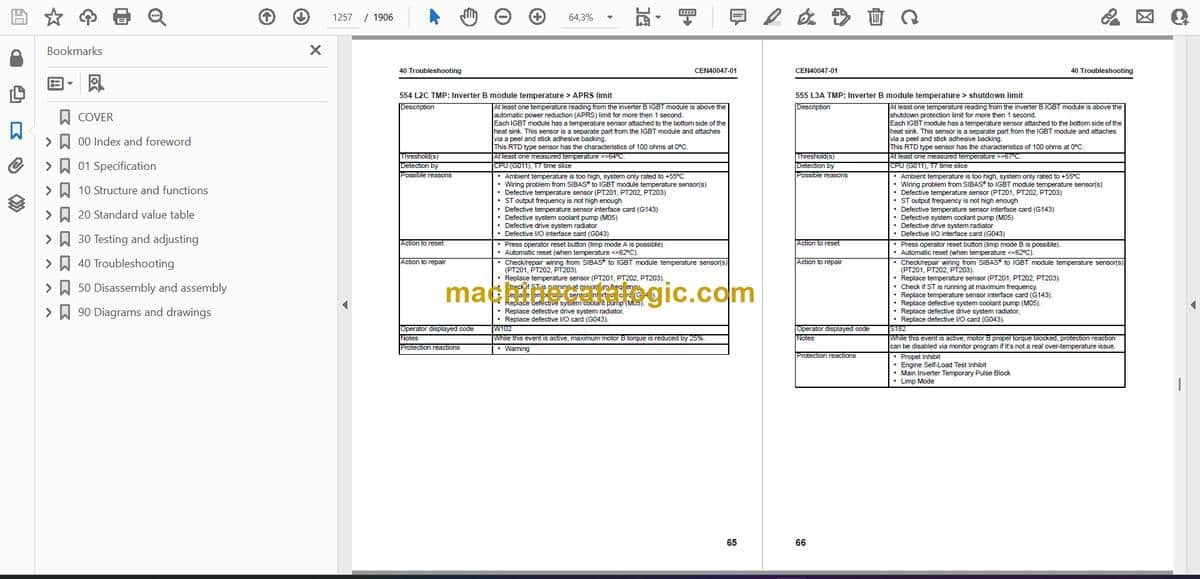