Format: PDF (Printable Document)
File Language: English
File Pages: 117
File Size: 10.19 MB (Speed Download Link)
Brand: Komatsu
Model: D155A-6 Bulldozer
Book No: GEN00078-08
Serial No: 85001 and up
Type of Document: Field Assembly Manual
$ 39
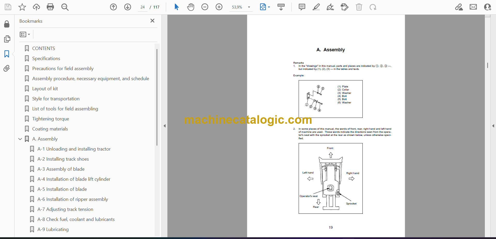
1. Major points changed from model 7
2. Outline of division (Only main components)
3. Dimensions of main components
4. Rough schedule of assembly and welding
5. List of equipments, tools, and consumables
Assembly process No.
List of jigs, tools, and consumables
0010 Oil, grease, and coolant
0020 Levels of oil, grease, and coolant
0030 Positioning rear axle assembly
0040 Installing rear suspension
0050 Installing of axle rod (upper)
0060 Slinging bare machine
0070 Installing rear axle assembly (Connecting axle rods)
0080 Connecting rear suspension
0085 Installation of tire and wheel assembly (Rear)
0090 Positioning bare machine
0100 Installing right front axle (Connecting A-arm)
0110 Installing right front axle (Connecting suspension)
0120 Installing right front axle (Connecting steering cylinder and tie rod)
0130 Installing right front axle (Connecting brake hose)
0140 Installing right front axle (Connecting piping for automatic suspension)
0145 Connection and fixing of right front axle wiring harness (ABS specification)
0146 Connection and fixing of right front centralized lubrication hoses [4-point greasing specification]
0150 Installing tire and wheel assembly
0160 Installing body hinge grease tube
0165 Installation of rear monitor
0170 Installing drive shaft
0180 Connecting cooling hose
0190 Connecting brake actuating hose
0195 Connection and fixing of rear centralized lubrication hoses [4-point greasing specification]
0200 Installing right front support
0210 Installing R.H platform assembly
0215 Fixing of ORBCOMM antenna cable
0216 Installation of ORBCOMM antenna pole
0220 Installing of fire prevention cover
0221 Installation of fire prevention cover (Sand terrain specification)
0230 Installing right fender
0231 Installation of right fender (Side lamp specification)
0240 Installing L.H catwalk assembly
0250 Installing L.H handrail
0251 Installation of cab side step (Diagonal ladder specification)
0252 Installation of diagonal ladder 1 (Diagonal ladder specification)
0253 Installation of diagonal ladder 2 (Diagonal ladder specification)
0254 Installation of diagonal ladder 3 (Diagonal ladder specification)
0255 Assembly of diagonal ladder (Diagonal ladder specification)
0256 Installation of under view mirror (Diagonal ladder specification)
0260 Installing radio antenna and fixing its cable
0270 Installing L.H fender
0271 Installation of left fender (Side lamp specification)
0280 Installing left side mudguard
0290 Installing right side mudguard
0295 Installation of R.H exhaust pipe cover (Muffler specification)
0296 Installation of R.H exhaust pipe cover (Exhaust selector box specification)
0300 Installing transmission underguard
0305 Installation of radiator curtain (Radiator curtain specification and sand terrain specification)
0310 Removing hoist cylinder bracket
0320 Removing hoist piping blind plate
0330 Welding body
0340 Slinging body
0350 Installing hinge pin
0360 Connecting hoist cylinder
0370 Welding protective cover by actually positioning it on machine
0380 Installing body mount
0390 Procedure for adjusting body mount shim
0395 Welding front body mount bracket
0400 Welding exhaust tube by actually positioning it on machine
0405 Installation of grease junction tube [4-point greasing specification]
0410 Installing rock ejector
0420 Installing body lock pin
0430 Installing body mudguard
0440 Connecting body positioner sensor
0450 Procedure for adjusting body positioner sensor
0460 Calibrating dump control
0470 Bleeding air from brake system (Preparation)
0480 Bleeding air from brake system (Front)
0490 Bleeding air from brake system (Rear)
0500 Adjusting suspension
0510 Greasing (Right front axle)
0520 Greasing (Hoist cylinder)
0530 Greasing (Rear suspension and axle rod)
0540 Painting
0550 Sticking body decal (1/2)
0555 Sticking body decal (2/2)
0560 Removing jig
0570 Adjusting angles of mirrors
0580 Checking/Adding lubricants
0590 Sticking of dump body tie-off decals
G350 Installation of cab
G420 Connection of steering column
G421 Connection of steering column – 1 (Auto-suspension type)
G422 Connection of steering column – 2 (Auto-suspension type)
G423 Connection of steering column – 3 (Auto-suspension type)
G900 Safety-critical section check sheet
G910 Check of inflation pressure of tires and inflation of them
C-0010 Preparation of welding body
C-0020 Assembly of split body
C-0030 Tack welding body
C-0040 Welding body
C-0050 Welding body instruction (1/2)
C-0060 Welding body instruction (2/2)
C-0070 Turn over the body
C-0080 Welding body protector (1/2)
C-0090 Welding body protector (2/2)
C-0100 Finishing and painting welded parts of body
C-0110 Reworking on body (Exhaust selector box specification)
C-0120 Welding of body exhaust pipe (Exhaust selector box specification)
Machine check sheet for field assmbly

