Format: PDF (Printable Document)
File Language: English
File Pages: 275
File Size: 18.51 MB (Speed Download Link)
Brand: Komatsu
Model: D375A-6R Bulldozer
Book No: GEN00164-05
Serial No: 65001 and up
Type of Document: Field Assembly Manual
$ 39
FOREWORD
CONTENTS
SPECIFICATIONS
PRECAUTIONS FOR FIELD ASSEMBLY
DISPOSAL OF REMOVED PARTS
ASSEMBLING PROCEDURES, APPLICABLE EQUIPMENT AND SCHEDULE
KIT LAYOUT DIAGRAM
TRANSPORTATION
LIST OF TOOLS FOR FIELD ASSEMBLING
TIGHTENING TORQUE
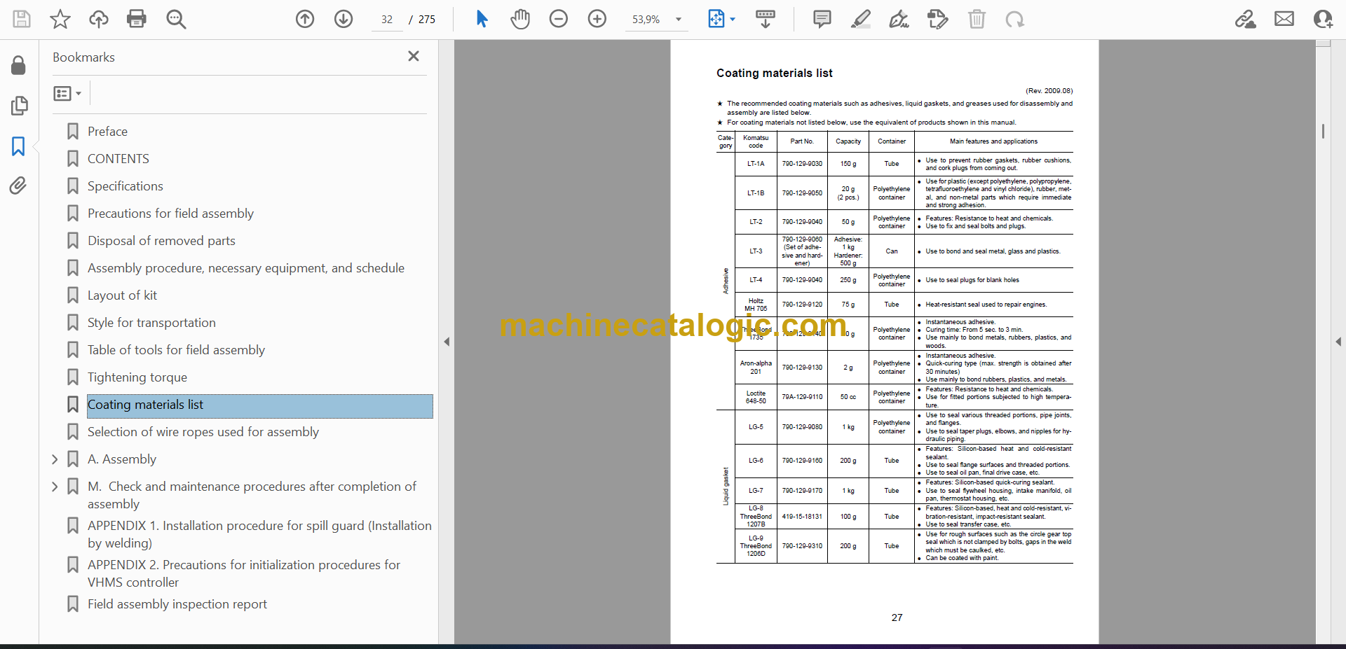
COATING MATERIALS
SELECTION OF WIRE ROPES USED FOR ASSEMBLY
A. ASSEMBLY OF CHASSIS
A-1 Installation of Left and Right Track Frames
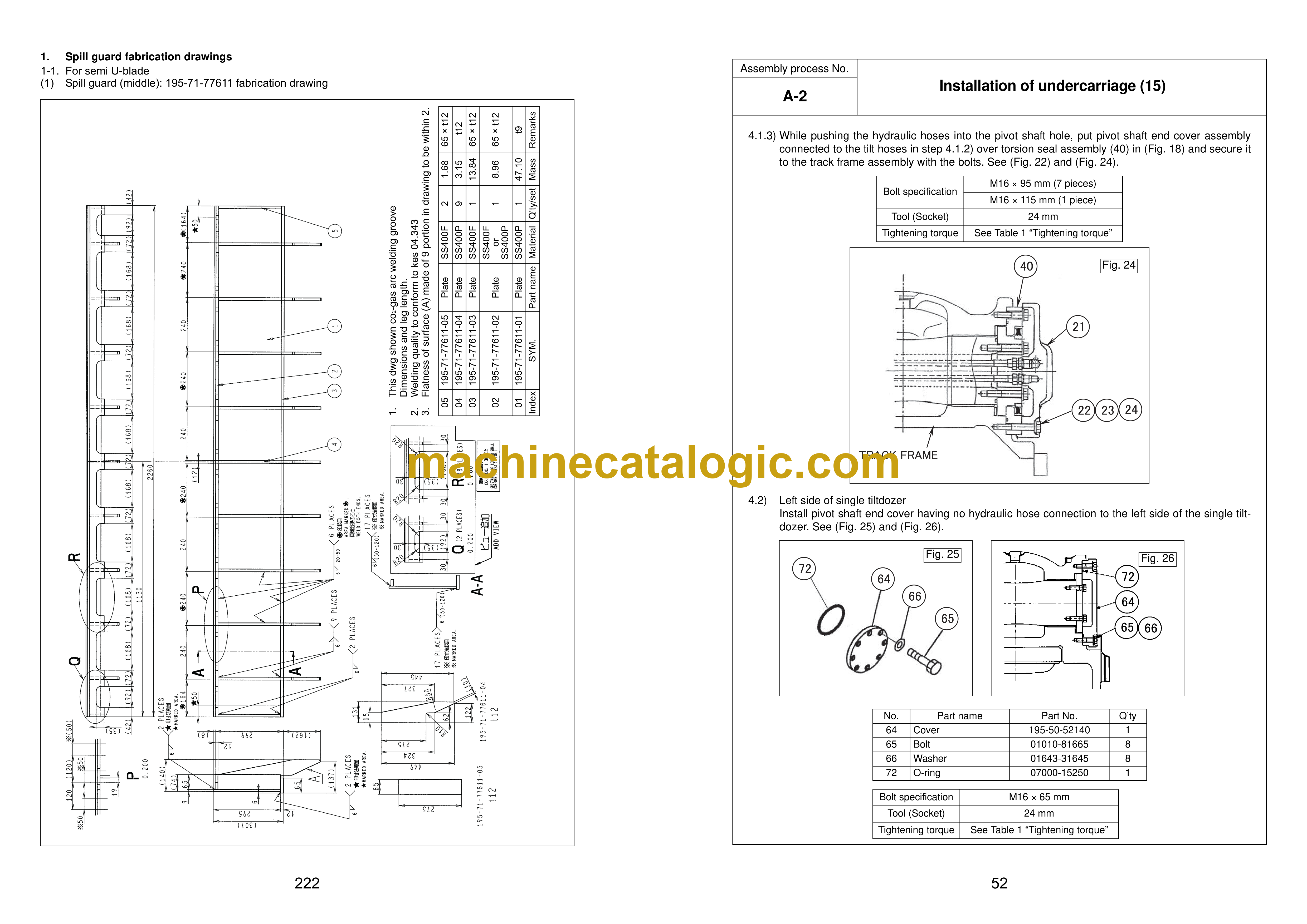
A-2 Installation of Travel Pipe
A-3 Installation of Operator Cab’s Left Handrail
A-4 Installation of Operator Cab’s Door Stopper and Striker
A-5 Installation of Rearview Mirror
A-6 Installation of Handrail
A-7-1 Installation of Step
A-7-2 Installation of Step
A-8 Installation of Left Side Step
A-9 Sticking Sheet to Counterweight
A-10 Installation of Rear View Camera
A-11 Installation of Counterweight
A-12 Installation of Step Light
A-13 Bleeding of Air from Travel Motor
A-14-1 Installation of Travel Piping Cover
A-14-2 Installation of Travel Piping Cover
A-15 Installation of Travel Motor Guard
A-16 Testing Track Shoe Tension
A-17 Check Fuel, Coolant and Oil Levels
B. ASSEMBLING OF WORK EQUIPMENT
B-1 Assembly of Arm Cylinder
B-2 Connection of Arm Cylinder Hoses
B-3 Installation of Boom Cylinder
B-4 Installation of Boom Cylinder Hoses
B-5 Installation of Boom Foot Dust Seal
B-6 Assembly of Boom Assembly
B-7 Installation of Hoses from Chassis Along Top of Boom
B-8 Connection of Boom Cylinder Head
B-9 Installation of Arm Assembly
B-10 Installation of Bucket Cylinder Hoses between Boom and Bucket Cylinder
B-11 Installation of Bucket
B-12 Connection of Work Equipment Grease Piping
B-13 Connection of Work Equipment Wiring
B-14 Greasing after Assembling Work Equipment
B-15 Bleeding Air from Work Equipment Circuit
B-16 Parts to be Touched up After Field Assembly
C. ASSEMBLING OF WORK EQUIPMENT OF LOADING SHOVEL
C-1 Releasing residual pressure in hydraulic circuit
C-2 Pulling out boom foot pin and boom cylinder foot pin
C-3 Installation of boom cylinder foot
C-4 Installation of boom and arm assembly
C-5 Installation of boom cylinder hoses
C-6 Installation of boom cylinder rod pin
C-7 Installation of boom cylinder
C-8 Installation of arm cylinder hoses
C-9 Installation of bucket cylinder
C-10 Installation of bucket cylinder hoses
C-11 Installation of connecting hoses between chassis and boom top
C-12 Installation of bottom dump cylinder hoses
C-13 Installation of bucket assembly
C-14 Installation of working lamps
C-15 Installation of work equipment grease piping
C-16 Grease after assembling of work equipment
C-17 Bleeding air from work equipment circuit
C-18 Checking oil level in hydraulic tank and adding oil
D. ASSEMBLING OF COUNTERWEIGHT REMOVER
D-1 Sticking Sheet to Counterweight
D-2 Adjustment of Shims for Counterweight
D-3 Greasing
D-4 Installation of Counterweight Remover
D-5 Installation of Covers
D-6 Installation of Clamps
D-7 Installation of Hoses
D-8 Bleeding Air from Counterweight Remover Circuit
D-9 Installation of Counterweight
D-10 Installation of Accessories
D-11 Check of Operation
M. PROCEDURE FOR INSPECTION AND MAINTENANCE AFTER COMPLETION OF ASSEMBLY
M-1 Inspection of Oil Level in Hydraulic Tank and Refill
M-2 Replacement of Return Filter (Standard Filter to Flushing Filter)
M-3 Flushing of Hydraulic Circuit
M-4 Replacement of Return Filter (Flushing Filter to Standard Filter)
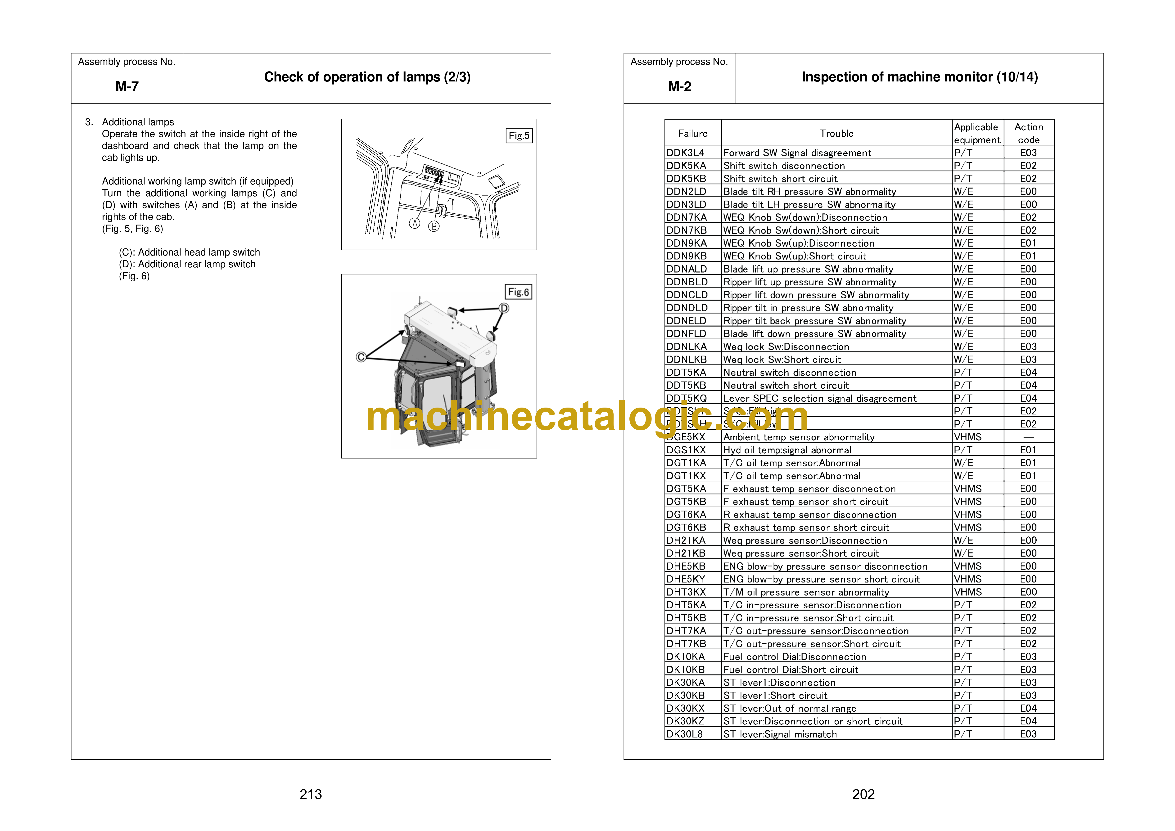
M-5 Failure code
M-6 Operating Method of Monitoring
FIELD ASSEMBLY INSPECTION REPORT (Backhoe)
FIELD ASSEMBLY INSPECTION REPORT (Loading shovel)


